


0目标
1 STM32 串口简介
2 硬件设计
3 软件设计
4 下载验证
0.目标
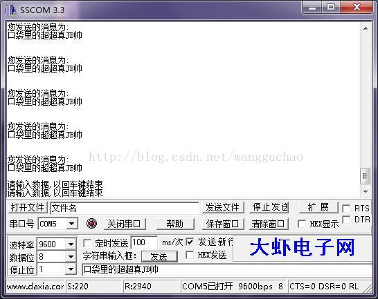
利用串口 1 不停的打印信息到电脑上,同时接收从串口发过来的数据,把发送过来的数据直接送回给电脑。
1.STM32 串口简介
串口设置的一般步骤可以总结为如下几个步骤:
1) 串口时钟使能, GPIO 时钟使能
2) 串口复位
3) GPIO 端口模式设置
4) 串口参数初始化
5) 开启中断并且初始化 NVIC(如果需要开启中断才需要这个步骤)
6) 使能串口
7) 编写中断处理函数
注:对于复用功能的 IO,我们首先要使能 GPIO 时钟,然后使能复用功能时钟,同时要把 GPIO 模式设置为复用功能对应的模式。
1) 串口时钟使能, GPIO 时钟使能
2) 串口复位
3) GPIO 端口模式设置
4) 串口参数初始化
5) 开启中断并且初始化 NVIC(如果需要开启中断才需要这个步骤)
6) 使能串口
7) 编写中断处理函数
注:对于复用功能的 IO,我们首先要使能 GPIO 时钟,然后使能复用功能时钟,同时要把 GPIO 模式设置为复用功能对应的模式。
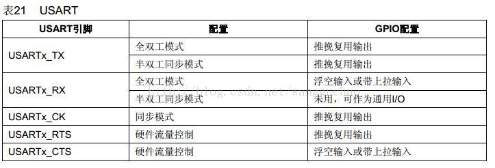
查看手册《STM32 中文参考手册 V10》P110 的表格“8.1.11 外设的 GPIO 配置:
2 硬件设计
(1)LED0接PA0
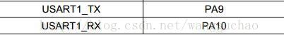
(2)串口1
3.软件设计
新建工程:
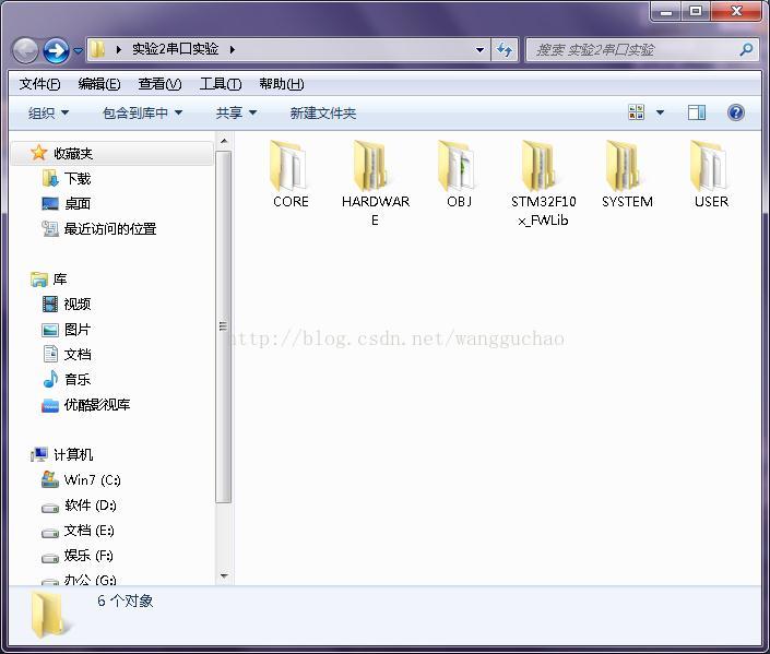
其中SYSTEM下放置原子哥提供的三个文件夹delay、sys、uart(及其文件),HARDWARE下建LED文件夹,及其内建LED.C与LED.H文件。
uart中串口函数:
void uart_init(u32 bound){
    //GPIO端口设置
    GPIO_InitTypeDef GPIO_InitStructure;
    USART_InitTypeDef USART_InitStructure;
    NVIC_InitTypeDef NVIC_InitStructure;

    RCC_APB2PeriphClockCmd(RCC_APB2Periph_USART1|RCC_APB2Periph_GPIOA, ENABLE);	//使能USART1,GPIOA时钟
     //USART1_TX   PA.9
    GPIO_InitStructure.GPIO_Pin = GPIO_Pin_9; //PA.9
    GPIO_InitStructure.GPIO_Speed = GPIO_Speed_50MHz;
    GPIO_InitStructure.GPIO_Mode = GPIO_Mode_AF_PP;	//复用推挽输出
    GPIO_Init(GPIOA, &GPIO_InitStructure);

    //USART1_RX	  PA.10
    GPIO_InitStructure.GPIO_Pin = GPIO_Pin_10;
    GPIO_InitStructure.GPIO_Mode = GPIO_Mode_IN_FLOATING;//浮空输入
    GPIO_Init(GPIOA, &GPIO_InitStructure);

   //Usart1 NVIC 配置

    NVIC_InitStructure.NVIC_IRQChannel = USART1_IRQn;
	NVIC_InitStructure.NVIC_IRQChannelPreemptionPriority=3 ;//抢占优先级3
	NVIC_InitStructure.NVIC_IRQChannelSubPriority = 3;		//子优先级3
	NVIC_InitStructure.NVIC_IRQChannelCmd = ENABLE;			//IRQ通道使能
	NVIC_Init(&NVIC_InitStructure);	//根据指定的参数初始化VIC寄存器

   //USART 初始化设置

	USART_InitStructure.USART_BaudRate = bound;//一般设置为9600;
	USART_InitStructure.USART_WordLength = USART_WordLength_8b;//字长为8位数据格式
	USART_InitStructure.USART_StopBits = USART_StopBits_1;//一个停止位
	USART_InitStructure.USART_Parity = USART_Parity_No;//无奇偶校验位
	USART_InitStructure.USART_HardwareFlowControl = USART_HardwareFlowControl_None;//无硬件数据流控制
	USART_InitStructure.USART_Mode = USART_Mode_Rx | USART_Mode_Tx;	//收发模式

    USART_Init(USART1, &USART_InitStructure); //初始化串口
    USART_ITConfig(USART1, USART_IT_RXNE, ENABLE);//开启中断
    USART_Cmd(USART1, ENABLE);                    //使能串口

}


LED.c内容:
#include "led.h"

//初始化PA0为输出口.并使能这个口的时钟
//LED IO初始化
void LED_Init(void)
{

 GPIO_InitTypeDef  GPIO_InitStructure;

 RCC_APB2PeriphClockCmd(RCC_APB2Periph_GPIOA, ENABLE);	 //使能PA端口时钟

 GPIO_InitStructure.GPIO_Pin = GPIO_Pin_0;				 //LED0-->PA0 端口配置
 GPIO_InitStructure.GPIO_Mode = GPIO_Mode_Out_PP; 		 //推挽输出
 GPIO_InitStructure.GPIO_Speed = GPIO_Speed_50MHz;		 //IO口速度为50MHz
 GPIO_Init(GPIOA, &GPIO_InitStructure);					 //根据设定参数初始化GPIOA0
 GPIO_SetBits(GPIOA,GPIO_Pin_0);						 //PA0 输出高
}
#ifndef __LED_H
#define __LED_H
#include "sys.h"

#define LED0 PAout(0)// PA0

void LED_Init(void);//初始化

#endif
主函数:
#include "led.h"
#include "delay.h"
#include "sys.h"
#include "usart.h"
 int main(void)
 {
 	u8 t;
	u8 len;
	u16 times=0;
	delay_init();	    	 //延时函数初始化
	NVIC_Configuration(); 	 //设置NVIC中断分组2:2位抢占优先级,2位响应优先级
	uart_init(9600);	 //串口初始化为9600
 	LED_Init();			     //LED端口初始化
 	while(1)
	{
		if(USART_RX_STA&0x8000)
		{
			len=USART_RX_STA&0x3f;//得到此次接收到的数据长度
			printf("\r\n您发送的消息为:\r\n\r\n");
			for(t=0;t<len;t++)
			{
				USART_SendData(USART1, USART_RX_BUF[t]);//向串口1发送数据
				while(USART_GetFlagStatus(USART1,USART_FLAG_TC)!=SET);//等待发送结束
			}
			printf("\r\n\r\n");//插入换行
			USART_RX_STA=0;
		}else
		{
			times++;
			if(times%5000==0)
			{
				printf("\r\n口袋里的超超 串口实验\r\n");
				printf("真JB帅\r\n\r\n");
			}
			if(times%200==0)printf("请输入数据,以回车键结束\n");
			if(times%30==0)LED0=!LED0;//闪烁LED,提示系统正在运行.
			delay_ms(10);
		}
	}
 }
4 下载验证


 2203
2203

 被折叠的 条评论
为什么被折叠?
被折叠的 条评论
为什么被折叠?
 到【灌水乐园】发言


