


一、简介
相位偏折术(Phase Deflectometry)是一种先进的光学测量技术,结合了相位测量偏折术,测量镜面物体,(Phase-Measuring Deflectometry, PMD)和结构光投影技术,主要用于高精度、非接触式的三维表面形貌检测 。
干涉法局限性:
- 测量自由面型的镜面物体时,干涉法所需要的光学补偿原件制作复杂且昂贵;
- 回程误差,干涉法很难快速标定;
- 测量环境苛刻,不适合干涉法测量,因为轻微抖动、温度变化,会给测量记过带来很大误差;
解决:PMD,相位偏折术,对环境不敏感,没有回程误差,因而标定相对简单,可以测量自由曲面。其实偏折术系统跟结构光系统是非常相似的,回顾下它的重建流程:
- 标定相机,以及屏幕、相机位置关系
- 使用屏幕投影条纹(结构光使用投影仪)
- 解码获取表面梯度(结构光直接获取高度)
- 梯度积分获取高度信息
综述 I 用于获取镜面 3D 形状的相位测量偏转法:对最新技术回顾 - 哔哩哔哩 (bilibili.com)
structured_light_partially_specular
相位偏折术原理概述 - 3D视觉工坊 - 博客园 (cnblogs.com)
二、基本原理
原理:
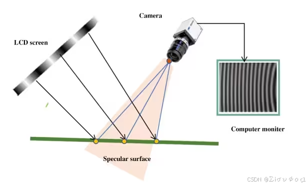
- 显示屏显示计算机生成的结构光条纹;
- 相机通过待测镜面表面拍摄显示屏上条纹的镜像;
- 如果镜面表面不平整的话,则拍摄到的条纹会产生相应的变形
详细原理:
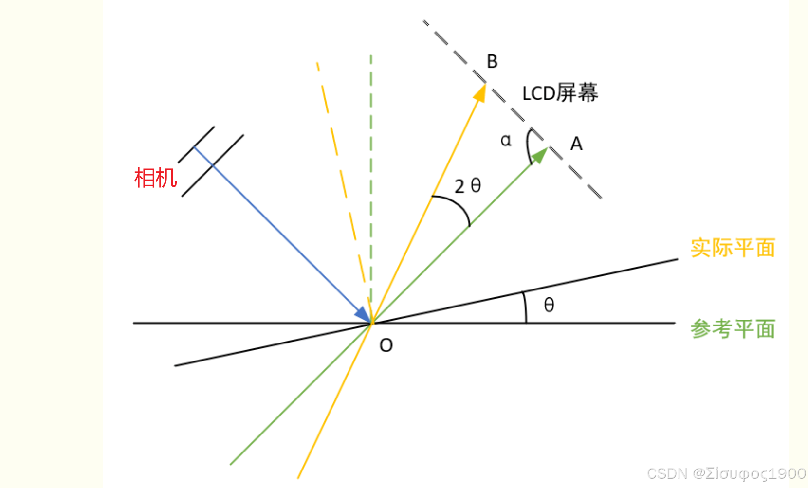
推导如下:
-
相位偏折术通过投射特定的光栅图案(如正弦条纹)到被测物体表面,相机捕捉因表面形变导致的条纹畸变,进而解算相位变化,重建表面斜率或高度信息。
-
关键步骤:
-
图案投影:投射多组相位移动的光栅图案(通常使用计算机屏幕或投影仪)。
-
图像采集:相机从不同角度捕获受物体表面调制后的变形条纹。
-
相位解调:通过相位移动算法(如四步相移法)提取绝对相位。
-
几何重建:根据相位变化与表面法向的关系,结合系统标定参数,计算表面三维形貌
-
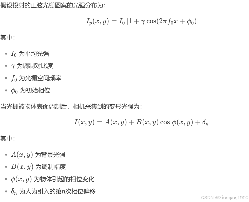
数学推导:
相位偏移法是一种通过投射多幅相位移动的结构光图案(如正弦光栅)并解调相位信息,从而恢复物体表面三维形貌的技术。其核心推导包括 光强模型建立、相位计算、相位解包裹、相位-高度映射 等步骤。以下是详细推导过程
光强模型建立
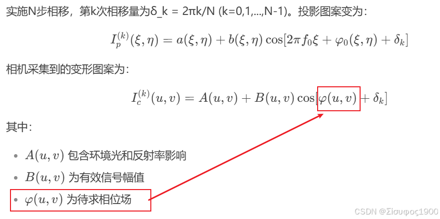
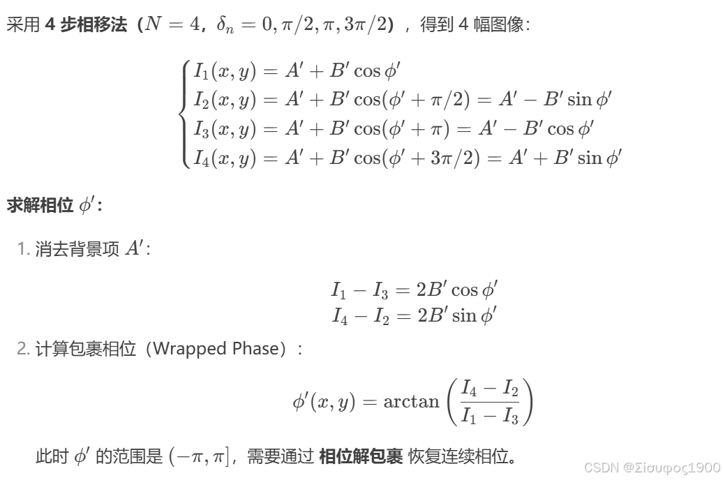
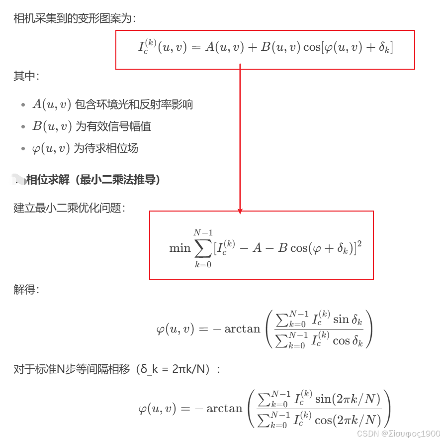
相位计算(以四步相移法为例)
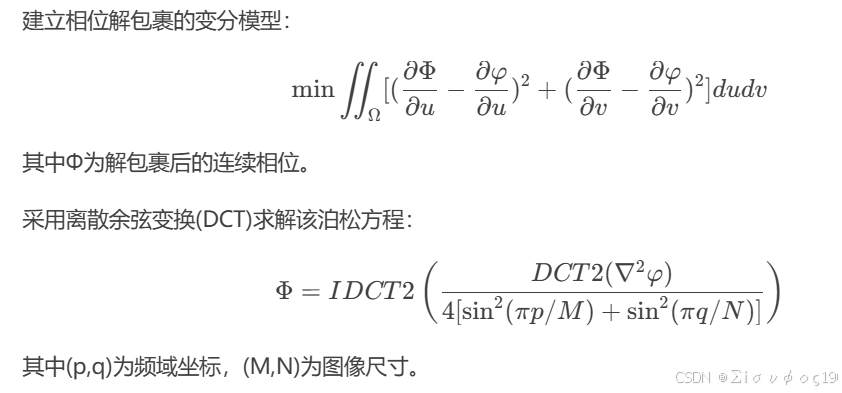
相位解包裹
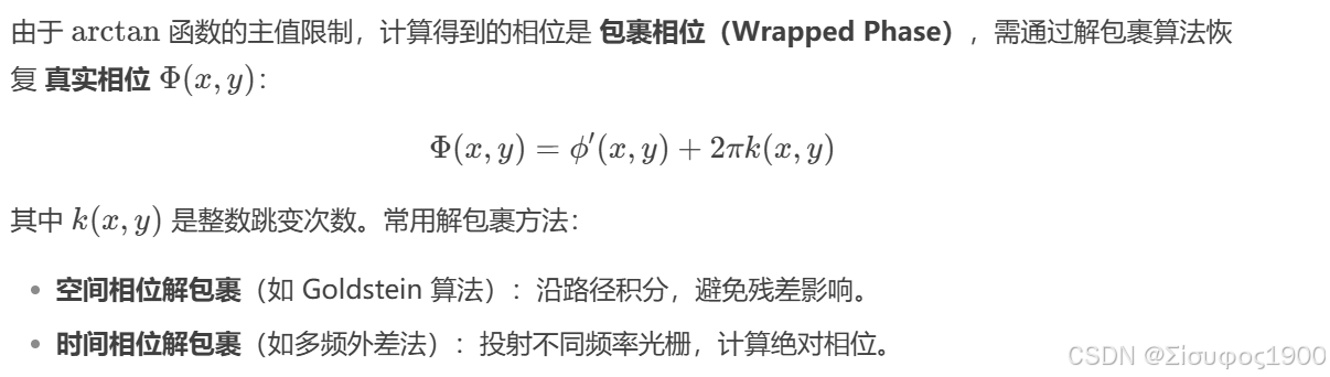
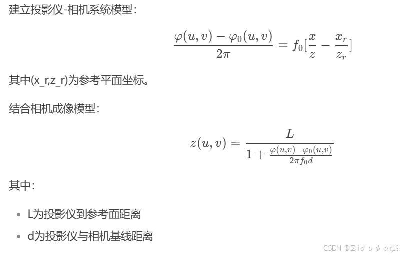
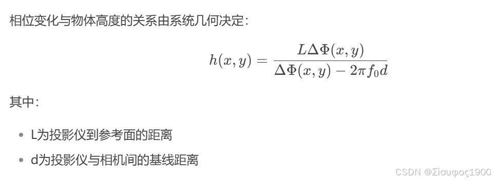
相位-高度映射
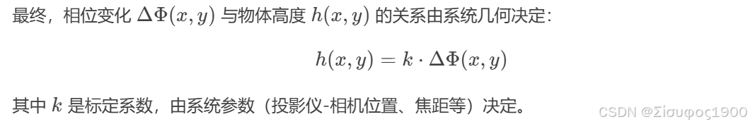
高度重建
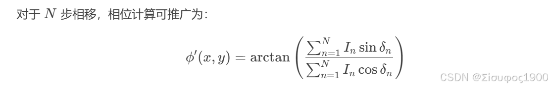
一般化 N 步相移公式
改进方法
-
增加相移步数(如 12 步法)提高抗噪能力。

-
使用格雷码+相移 结合绝对相位解算。
-
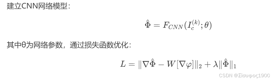
深度学习去噪:用神经网络优化相位计算。
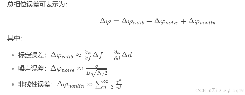
误差来源
-
非线性响应:相机或投影仪的 Gamma 校正导致非理想正弦条纹。
-
环境光干扰:背景光影响 A(x,y)A(x,y) 的稳定性。
-
振动噪声:动态测量时引入相位误差。
-
解包裹错误:在复杂表面或遮挡区域可能跳变
技术特点
-
高精度:亚微米级分辨率,适用于光学元件、精密加工表面的检测。
-
全视野测量:可一次性测量大范围区域,无需逐点扫描。
-
动态能力:适合动态表面或振动环境下的实时测量。
-
无需喷涂:对反射表面(如镜面、金属)直接测量,无需喷显影剂
与传统方法的对比
应用领域
-
光学元件检测:透镜、反射镜的面形误差(如RMS、PV值)。
-
工业制造:汽车、航空航天部件的表面质量评估。
-
半导体:晶圆、光刻掩模板的平整度测量。
-
生物医学:角膜、人工关节的表面分析。
-
系统标定:需精确校准投影仪-相机几何关系,误差敏感。
-
环境光干扰:强光环境下需屏蔽或使用主动光源。
-
高反射表面:可能需偏振滤波或多曝光策略抑制过曝。
-
算法优化:深度学习正被用于相位解算和噪声抑制。
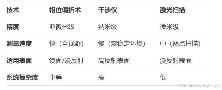
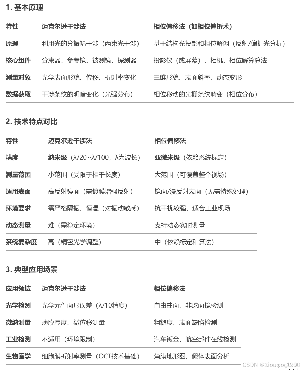
三、迈克尔逊干涉法和相位偏移法对比
四、Halcon案例
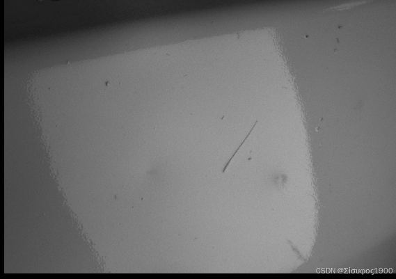
* This example shows how to improve defect detection on partially
* specular surfaces using deflectometry.
*
* For partially specular surfaces it is often the case that multiple
* artifacts are detected and defects are hence not clearly found. In
* these scenarios, it is recommended to use the
* pattern_type='single_stripe' with a suitable single_stripe_width.
*
* The following example shows the improved defect detection that can
* be achieved with this pattern type in comparison to the default type.
* For a detailed example of the workflow of detection with deflectometry,
* please refer to the example 'structured_light_tap_collar.hdev'.
*
dev_update_off ()
dev_close_window ()
dev_open_window (0, 0, 600, 450, 'black', WindowHandle1)
set_display_font (WindowHandle1, 14, 'mono', 'true', 'false')
*
dev_disp_intro_text ()
stop ()
dev_set_draw ('margin')
dev_set_line_width (3)
*
* 1. Create the structured light model with the default pattern_type
* gray_code_and_phase_shift and set its necessary parameters.
create_structured_light_model ('deflectometry', StructuredLightModel)
*
PatternWidth := 1600
PatternHeight := 1200
MinStripeWidth := 32
MinGrayDifference := 0
Persistence := 'true'
Normalization := 'inverted_pattern'
set_structured_light_model_param (StructuredLightModel, ['pattern_width','pattern_height','min_stripe_width','min_gray_difference','normalization','persistence'], [PatternWidth,PatternHeight,MinStripeWidth,MinGrayDifference,Normalization,Persistence])
* 2. Acquire and decode images with this model and visualize the
* resulting defect image.
*
* Generate the pattern images.
gen_structured_light_pattern (PatternImages, StructuredLightModel)
* Read in the camera images and decode them.
count_obj (PatternImages, Number)
gen_empty_obj (CameraImages)
for Index := 1 to Number by 1
read_image (Image, 'structured_light/varnished_metal_sheet/varnished_metal_sheet_' + Index$'02' + '.png')
concat_obj (CameraImages, Image, CameraImages)
endfor
stop ()
* Decode the structured light pattern.
decode_structured_light_pattern (CameraImages, StructuredLightModel)
* Get the binarized images.
get_structured_light_object (BinarizedImages, StructuredLightModel, 'binarized_image')
stop ()
InspectSegmentation := 'false'
*
dev_open_window (0, 609, 600, 450, 'black', WindowHandle2)
set_display_font (WindowHandle2, 14, 'mono', 'true', 'false')
*
* 3. Check whether the bright/dark decoding is correct.
* The idea here is to call the procedure and check
* whether the decoded bright regions match the bright
* regions on the camera images. If they don't match,
* as in this example, it is an indication that the
* decoding was wrong. This is usually because the surface
* is partially specular and indicates that 'single_stripe'
* pattern should be used.
* Please uncomment the following lines to run the check.
if (InspectSegmentation == 'true')
select_obj (CameraImages, CameraImagesGC, [1:2:28])
dev_set_window (WindowHandle2)
dev_clear_window ()
Text := 'The decoded bright regions for min_gray_difference = 0.'
Text[1] := ' '
Text[2] := 'If the visualized region does not match the bright region on the'
Text[3] := 'camera image, then the decoding was incorrect.'
dev_disp_text (Text, 'window', 'top', 'left', 'white', 'box', 'false')
gen_structured_light_pattern (PatternImages, StructuredLightModel)
decode_structured_light_pattern (CameraImages, StructuredLightModel)
get_structured_light_object (BinarizedImages, StructuredLightModel, 'binarized_image')
structured_light_inspect_segmentation (CameraImagesGC, BinarizedImages, WindowHandle1)
endif
* Visualize the first 2 camera images to show the effect of the used
* inverted_pattern normalization.
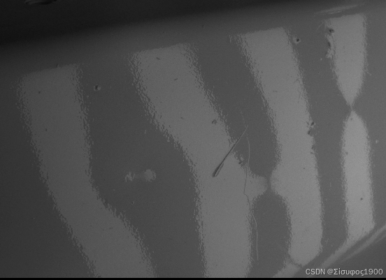
select_obj (CameraImages, CameraImage1, 1)
select_obj (CameraImages, CameraImage2, 2)
dev_set_window (WindowHandle1)
dev_display (CameraImage1)
dev_disp_text ('First camera image.', 'window', 12, 12, 'black', [], [])
dev_set_window (WindowHandle2)
dev_display (CameraImage2)
dev_disp_text ('Second camera image that corresponds to the inverted pattern\nof the first pattern image.', 'window', 12, 12, 'black', [], [])
dev_open_window (510, 0, 900, 220, 'black', WindowHandle3)
set_display_font (WindowHandle3, 14, 'mono', 'true', 'false')
dev_disp_inverted_pattern_text ()
stop ()
*
dev_set_window (WindowHandle1)
dev_clear_window ()
dev_set_line_width (3)
convert_image_type (CameraImage1, CamImage1, 'real')
convert_image_type (CameraImage2, CamImage2, 'real')
sub_image (CamImage1, CamImage2, DiffImage, 1, 0)
dev_display (DiffImage)
dev_disp_text ('Difference image of the first two camera images\nwith region where the first image is brighter\nthan the second.', 'window', 12, 12, 'black', [], [])
threshold (DiffImage, BrighterInFirstImage, 0, 255)
dev_display (BrighterInFirstImage)
dev_set_window (WindowHandle2)
dev_clear_window ()
dev_display (BinarizedImages)
dev_disp_text ('The corresponding binarized image with partially wrong\nidentified white and black pixels.', 'window', 12, 12, 'black', [], [])
dev_set_window (WindowHandle3)
dev_disp_problem_text ()
stop ()
dev_close_window ()
* Get the computed correspondence images.
get_structured_light_object (CorrespondenceImages, StructuredLightModel, 'correspondence_image')
dev_set_window (WindowHandle1)
dev_clear_window ()
dev_display (CorrespondenceImages)
dev_disp_text ('A wrongly decoded correspondence image.', 'window', 12, 12, 'black', [], [])
gen_rectangle1 (ProblematicRegion, 130, 1050, 900, 1270)
dev_display (ProblematicRegion)
dev_set_window (WindowHandle2)
dev_disp_wrong_correspondence ()
stop ()
* Get the defect image and scale it.
get_structured_light_object (DefectImage, StructuredLightModel, 'defect_image')
scale_image_range (DefectImage, ScaledDefectImage, 0, 4)
dev_set_window (WindowHandle1)
dev_clear_window ()
dev_display (ScaledDefectImage)
dev_display (ProblematicRegion)
dev_disp_text ('Scaled defect image with default pattern_type.', 'window', 12, 12, 'black', [], [])
dev_set_window (WindowHandle2)
dev_disp_wrong_defect ()
stop ()
*
*
* 4. Create another structured light model with the pattern_type
* single_stripe and set the necessary parameters.
create_structured_light_model ('deflectometry', StructuredLightModelSS)
PatternType := 'single_stripe'
SingleStripeWidth := 64
set_structured_light_model_param (StructuredLightModelSS, ['pattern_width','pattern_height','min_stripe_width','min_gray_difference','pattern_type','single_stripe_width','persistence'], [PatternWidth,PatternHeight,MinStripeWidth,MinGrayDifference,PatternType,SingleStripeWidth,Persistence])
* 5. Acquire and decode images with this improved model and visualize
* the improved defect image.
*
* Generate the pattern images.
gen_structured_light_pattern (PatternImagesSS, StructuredLightModelSS)
dev_open_window (510, 0, 900, 220, 'black', WindowHandle3)
set_display_font (WindowHandle3, 14, 'mono', 'true', 'false')
dev_disp_single_stripe_text ()
* Read in the camera images and decode them.
dev_set_window (WindowHandle1)
SingleStripesNum := round((PatternWidth + PatternHeight) / real(SingleStripeWidth))
count_obj (PatternImagesSS, NumberSS)
gen_empty_obj (CameraImagesSS)
for Index := 1 to NumberSS by 1
select_obj (PatternImagesSS, Image, Index)
read_image (CameraImage, 'structured_light/varnished_metal_sheet/varnished_metal_sheet_single_stripe_' + Index$'02' + '.png')
if (Index <= SingleStripesNum)
* Display the single stripe image.
dev_set_window (WindowHandle1)
dev_display (Image)
dev_disp_text ('Single stripe image.', 'window', 'top', 'left', 'black', [], [])
* Display the corresponding camera image.
dev_set_window (WindowHandle2)
dev_display (CameraImage)
dev_disp_text ('Corresponding camera image.', 'window', 'top', 'left', 'black', [], [])
wait_seconds (0.1)
endif
concat_obj (CameraImagesSS, CameraImage, CameraImagesSS)
endfor
stop ()
dev_set_window (WindowHandle3)
dev_close_window ()
decode_structured_light_pattern (CameraImagesSS, StructuredLightModelSS)
* Get the computed correspondence images.
get_structured_light_object (CorrespondenceImagesSS, StructuredLightModelSS, 'correspondence_image')
dev_disp_comparison (CorrespondenceImagesSS, CorrespondenceImages, WindowHandle1, WindowHandle2, 'Correspondence image with single_stripe shows\n - expected gradual change in gray values,\n - no abrupt changes.', 'Correspondence image with default pattern_type')
stop ()
* Get the defect image and scale it.
get_structured_light_object (DefectImageSS, StructuredLightModelSS, 'defect_image')
scale_image_range (DefectImageSS, ScaledDefectImageSS, 0, 4)
dev_disp_comparison (ScaledDefectImageSS, ScaledDefectImage, WindowHandle1, WindowHandle2, 'Scaled defect image with single_stripe shows\n - more pronounced defects in comparison to the background,\n - no problematic regions where defects are not detected.', 'Scaled defect image with default pattern_type')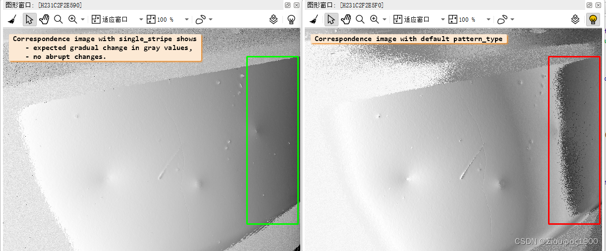


 2505
2505

 被折叠的 条评论
为什么被折叠?
被折叠的 条评论
为什么被折叠?
 到【灌水乐园】发言


