


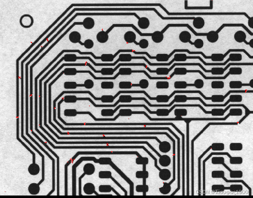
一、电路检测
算子解释
dyn_threshold
*dyn_threshold 利用局部阈值分割图像
*OrigImage (input_object):原始图像
*ThresholdImage (input_object):处理后图像(一般采用滤波处理)
*RegionDynThresh (output_object):分割后区域
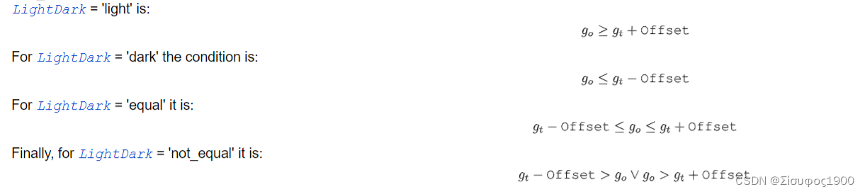
*Offset (input_control):灰度值偏移量。
*LightDark (input_control):提取区域类型( ‘dark’, ‘equal’, ‘light’, ‘not_equal’)
dyn_threshold (ImageOpening, ImageClosing, RegionDynThresh, 75, 'not_equal')原理介绍
halcon 源码
    * 电路检测方案
read_image (Image, 'pcb')
dev_close_window ()
get_image_size (Image, Width, Height)
dev_open_window (0, 0, Width, Height, 'black', WindowHandle)
dev_display (Image)
* 开闭图像做减法 得到不同的区域

gray_opening_shape (Image, ImageOpening, 7, 7, 'octagon')
gray_closing_shape (Image, ImageClosing, 7, 7, 'octagon')

*dyn_threshold  局部区域阈值
      *OrigImage (input_object):原始图像
      *ThresholdImage (input_object):处理后图像(一般采用滤波处理)
      *RegionDynThresh (output_object):分割后区域
      *Offset (input_control):灰度值偏移量。
      *LightDark (input_control):提取区域类型( ‘dark’, ‘equal’, ‘light’, ‘not_equal’)
dyn_threshold (ImageOpening, ImageClosing, RegionDynThresh, 75, 'not_equal')
dev_display (Image)
dev_set_color ('red')
dev_set_draw ('margin')
dev_display (RegionDynThresh)
二、毛刺检测
算子解释
    *用二进制阈值来分割图像。

    *Image:需要进行阈值的图像
    *Region:处理后的区域 输出
    *Method:分割方法('max_separability':最大限度的可分性,   'smooth_histo':直方图平滑)
    *LightDark:提取的是黑色部分还是白色部分
            *当LightDark=light,max_separability选的区域比smooth_histo少一点
            *当LightDark=dark,max_separability选的区域比smooth_histo多一点
    *UsedThreshold:自动阈值使用的阈值
    binary_threshold (Fin, Background, 'max_separability', 'light', UsedThreshold)
halcon 源码
* 毛刺检测案例
*思路:通过二值化将图像分开,然后消除减小区域 ,最后做区域的减法  显示
dev_update_window ('off')
read_image (Fins, 'fin' + [1:3])
get_image_size (Fins, Width, Height)
dev_close_window ()
dev_open_window (0, 0, Width[0], Height[0], 'black', WindowID)
set_display_font (WindowID, 14, 'mono', 'true', 'false')
for I := 1 to 3 by 1
    select_obj (Fins, Fin, I)
    dev_display (Fin)


    *用二进制阈值来分割图像。

    *Image:需要进行阈值的图像
    *Region:处理后的区域 输出
    *Method:分割方法('max_separability':最大限度的可分性,   'smooth_histo':直方图平滑)
    *LightDark:提取的是黑色部分还是白色部分
            *当LightDark=light,max_separability选的区域比smooth_histo少一点
            *当LightDark=dark,max_separability选的区域比smooth_histo多一点
    *UsedThreshold:自动阈值使用的阈值
    binary_threshold (Fin, Background, 'max_separability', 'light', UsedThreshold)
    dev_set_color ('blue')
    dev_set_draw ('margin')
    dev_set_line_width (4)
    dev_display (Background)
    disp_continue_message (WindowID, 'black', 'true')
    stop ()
    *用圆形区域进行闭运算,能达到保留圆弧边,消除毛刺效果
    closing_circle (Background, ClosedBackground, 250)
    dev_set_color ('green')
    dev_display (ClosedBackground)
    disp_continue_message (WindowID, 'black', 'true')
    stop ()
    *背景差分,得出不同点
    difference (ClosedBackground, Background, RegionDifference)
    *用矩形开操作去除小点,保留真正的差异点
    opening_rectangle1 (RegionDifference, FinRegion, 5, 5)
    dev_display (Fin)
    dev_set_color ('red')
    dev_display (FinRegion)
    *得到真正差异点的面积和中心点
    area_center (FinRegion, FinArea, Row, Column)
    if (I < 3)
        disp_continue_message (WindowID, 'black', 'true')
        stop ()
    endif
endfor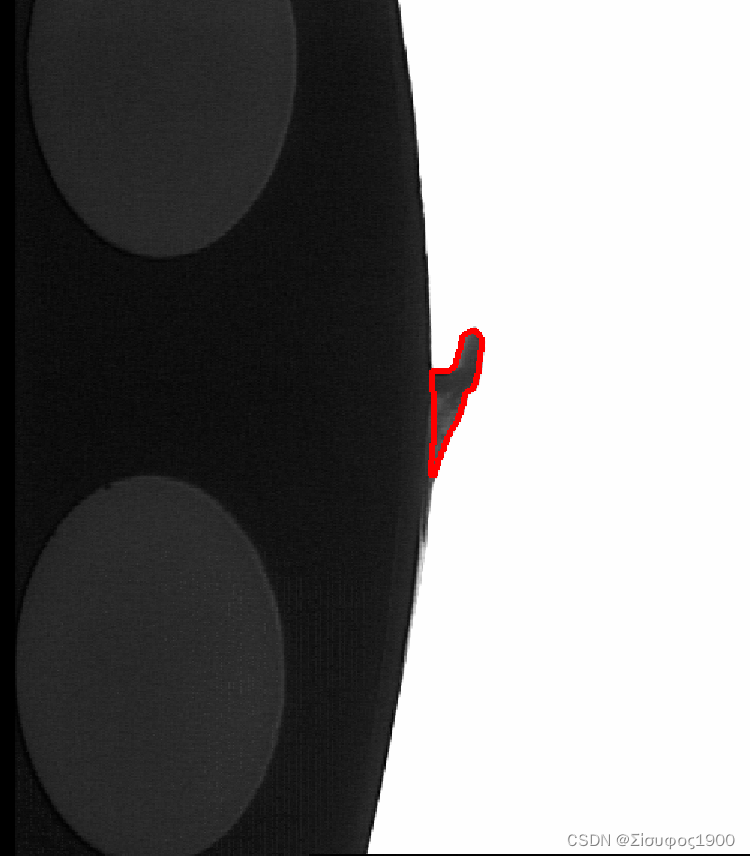
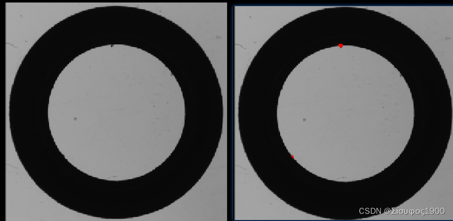
三、圆环检测
* 毛刺检测
read_image (Image2, 'D:/workplace/缺陷检测项目/2.png')
rgb1_to_gray (Image2, GrayImage1)
* 外圆检测
threshold (GrayImage1, Region2, 0, 127)
connection (Region2, ConnectedRegions2)
select_shape_std (ConnectedRegions2, SelectedRegions3, 'max_area', 700)
fill_up (SelectedRegions3, RegionFillUp)
dev_display (GrayImage1)
opening_circle (RegionFillUp, RegionOpening2, 3.5)

* 最小外接圆
smallest_circle (RegionOpening2, Row2, Column2, Radius)
    CenterRow[0]:=Row2
    CenterColumn[0]:=Column2
    CenterRadius[0]:=Radius
*开始提取内圆
difference (RegionFillUp, SelectedRegions3, RegionDifference2)
smallest_circle (RegionDifference2, Row3, Column3, Radius1)
    CenterRow[1]:=Row3
    CenterColumn[1]:=Column3
    CenterRadius[1]:=Radius1
dev_display (GrayImage1)
* 使用二维测量圆来做  内外圆的测量
create_metrology_model (MetrologyHandle)
add_metrology_object_circle_measure (MetrologyHandle, CenterRow, CenterColumn, CenterRadius, CenterRadius[0]/10, CenterRadius[0]/60, 1, 4, ['measure_distance','min_score'], [CenterRadius[0]/30,0.2], Indexnumb)
    *进行测量
apply_metrology_model (GrayImage1, MetrologyHandle)
 *得到测量结果
get_metrology_object_result (MetrologyHandle, 'all', 'all', 'result_type', 'all_param', Parameter)

get_metrology_object_result_contour (Contour, MetrologyHandle, 'all', 'all', 1.5)

get_metrology_object_measures (Contours, MetrologyHandle, 'all', 'all',  Row4, Column4)
    *****求出标准圆环,进行缺陷检测
gen_cross_contour_xld (Cross, Row4, Column4, 6, 0.785398)
RadiusOffest:=5
dev_display (GrayImage1)
*外部的如何检测
    gen_circle (Circle, Parameter[0], Parameter[1], Parameter[2])
    difference (Circle, RegionOpening2, RegionDifference4)
    opening_circle (RegionDifference4, region, 1.0)
    connection (region, ConnectedRegions4)
    select_shape (ConnectedRegions4, SelectedRegions5, 'area', 'and', 10, 34.7474)
    gen_contour_region_xld (SelectedRegions5, Contours2, 'border')
dev_display (GrayImage1)
* *内圆的部分
    gen_circle (Circle3,Parameter[3], Parameter[4], Parameter[5]+1)
    difference (Circle3, RegionDifference2, RegionDifference3)
    opening_circle (RegionDifference3, RegionOpening3, 1.5)
    connection (RegionOpening3, ConnectedRegions3)
    select_shape (ConnectedRegions3, SelectedRegions4, 'area', 'and', 10, 94.7474)
    gen_contour_region_xld (SelectedRegions4, Contours1, 'border')

    union2 (SelectedRegions5, SelectedRegions4, RegionUnion1)
    dev_display (GrayImage1)
    dev_display (RegionUnion1)
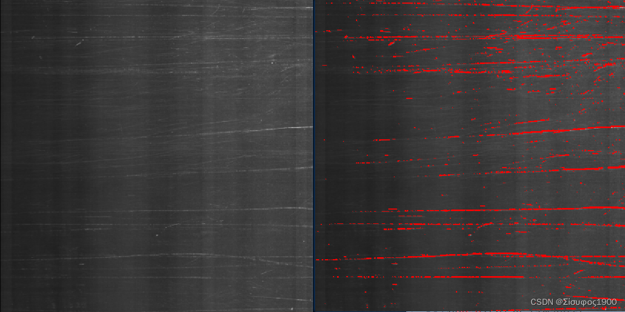
四、磨砂表面
算子:
cooc_feature_image(计算图像的灰度共生矩阵)
cooc_feature_image(Regions, Image ,LdGray, Direction ,Energy, Correlation, Homogeneity, Contrast)

参数列表:
Regions(in)     //要检查的区域。
Image (in)      //灰度图像。
LdGray(in)       //要区分的灰度值的数量。(默认6)
Direction (in)  //矩阵的计算方向('0','45','90','130','mean‘)
Energy(out)     //能量  反应的是图像灰度分布情况,越大越稳定
Correlation(out)//相关性
Homogeneity(out) //局部均匀性(熵) 反映图像局部纹理的变化量(即复杂程度),熵值越大图像越复杂
Contrast(out)   //对比度(反差)  表示矩阵的值的差异程度,也间接表现了图像的局部灰度变化幅度。反差值越大,图像中的纹理深浅越明显,表示图像越清晰;反之,则表示图像越模糊。
watersheds_threshold(阈值分水岭图像分割)
watersheds_threshold(Image ,Basins ,Threshold )

参数列表:
Image(in)//输入图像(最好先用中值滤波处理)
Basins(out)//输出二值图像(盆地)
Threshold(in)//阈值

第一步:计算出分水岭(不使用该参数Threshold ),分割的盆地和调用算子watersheds得到的盆地是相同的
第二步:如果被一个分水岭分割的相邻盆地与对应分水岭的高度差小于Threshold ,盆地依次合并。假设B1和B2分别是两个相邻盆地的最小灰度值,W是盆地对应分水岭的最小灰度值。当满足以下条件时,两个盆地合并:max{W-B1,W-B2}<Threshold 。由此得到的盆地存储在Basins 变量中。
halcon 源码
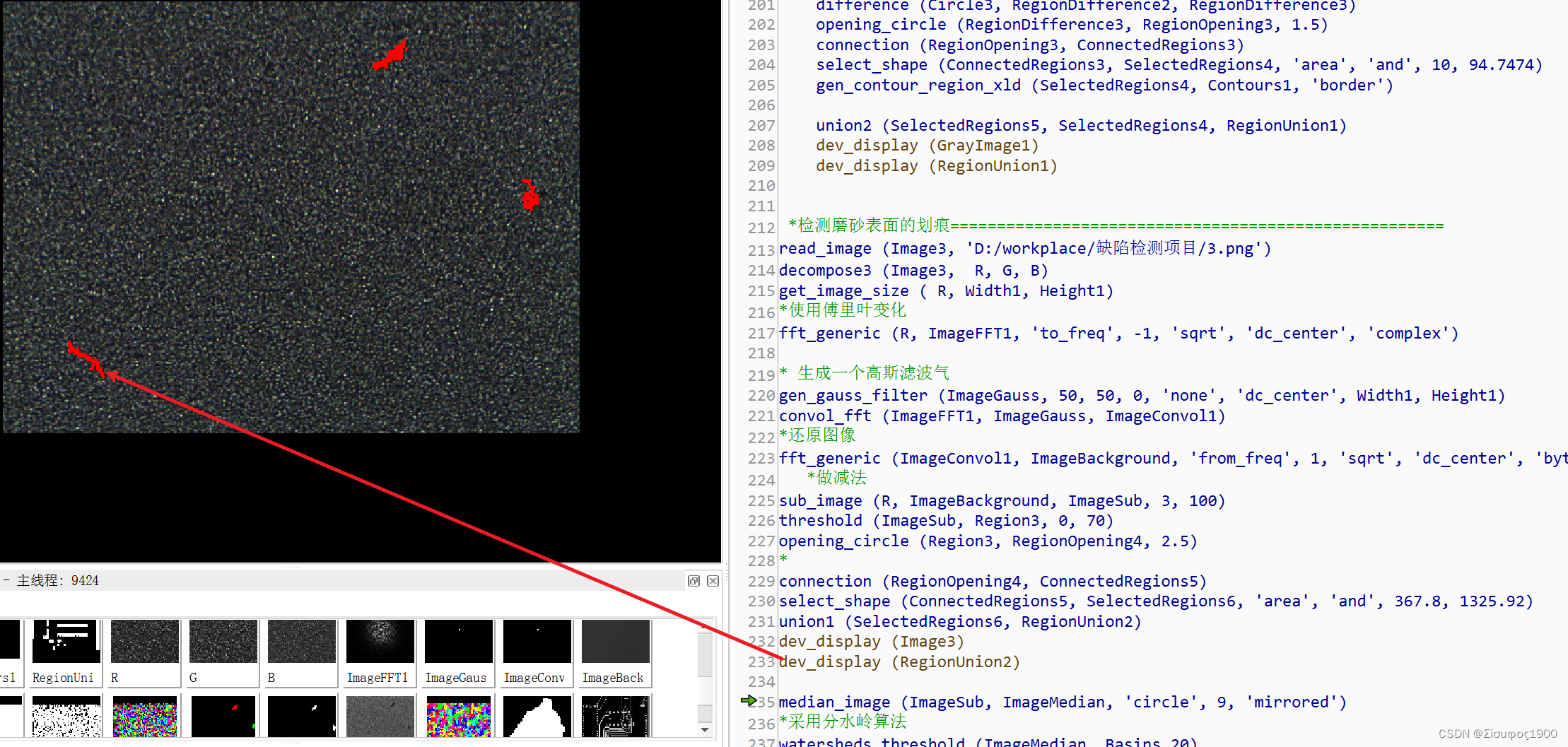
 *检测磨砂表面的划痕=====================================================
read_image (Image3, 'D:/workplace/缺陷检测项目/3.png')
decompose3 (Image3,  R, G, B)
get_image_size ( R, Width1, Height1)
*使用傅里叶变化
fft_generic (R, ImageFFT1, 'to_freq', -1, 'sqrt', 'dc_center', 'complex')

* 生成一个高斯滤波气
gen_gauss_filter (ImageGauss, 50, 50, 0, 'none', 'dc_center', Width1, Height1)
convol_fft (ImageFFT1, ImageGauss, ImageConvol1)
*还原图像
fft_generic (ImageConvol1, ImageBackground, 'from_freq', 1, 'sqrt', 'dc_center', 'byte')
   *做减法
sub_image (R, ImageBackground, ImageSub, 3, 100)
threshold (ImageSub, Region3, 0, 70)
opening_circle (Region3, RegionOpening4, 2.5)
*
connection (RegionOpening4, ConnectedRegions5)
select_shape (ConnectedRegions5, SelectedRegions6, 'area', 'and', 367.8, 1325.92)
union1 (SelectedRegions6, RegionUnion2)
dev_display (Image3)
dev_display (RegionUnion2)

median_image (ImageSub, ImageMedian, 'circle', 9, 'mirrored')
*采用分水岭算法
watersheds_threshold (ImageMedian, Basins,20)
*计算共生矩阵
* 缺陷部分是黑色的,灰度值小能量就小,所以根据能量可以将缺陷的区域筛选出来

*cooc_feature_image(Regions, Image ,LdGray, Direction ,Energy, Correlation, Homogeneity, Contrast)

*参数列表:
*Regions(in)     //要检查的区域。
*Image (in)      //灰度图像。
*LdGray(in)       //要区分的灰度值的数量。(默认6)
*Direction (in)  //矩阵的计算方向('0','45','90','130','mean‘)
*Energy(out)     //能量  反应的是图像灰度分布情况,越大越稳定
*Correlation(out)//相关性
*Homogeneity(out) //局部均匀性(熵) 反映图像局部纹理的变化量(即复杂程度),熵值越大图像越复杂
*Contrast(out)   //对比度(反差)  表示矩阵的值的差异程度,也间接表现了图像的局部灰度变化幅度。反差值越大,图像中的纹理深浅越明显,表示图像越清晰;反之,则表示图像越模糊。
cooc_feature_image (Basins, ImageMedian, 5, 0, Energy, Correlation, Homogeneity, Contrast)
Mask := Energy [<=] 0.05
select_mask_obj (Basins, Defects, Mask)
dev_display (Image3)
dev_display (Defects)
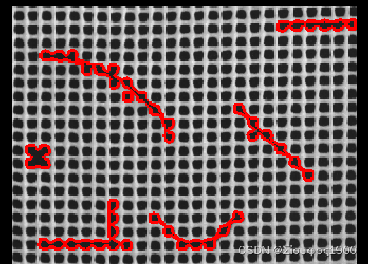
五、网状表面检测
*关闭程序计数器,图形变量更新,窗口图形更新
dev_update_window ('off')
*读取一张图像
read_image (Image, 'plastic_mesh/plastic_mesh_01')
*关闭打开的窗口
dev_close_window ()
*获取图像大小
get_image_size (Image, Width, Height)
*创建一个新窗口
dev_open_window_fit_image (Image, 0, 0, Width, Height, WindowHandle)
*设置字体信息:字体大小为16,字体为mono,粗体,斜体
set_display_font (WindowHandle, 18, 'mono', 'true', 'false')
*设置区域的填充方式
dev_set_draw ('margin')
*设置线宽度
dev_set_line_width (3)
for J := 1 to 14 by 1
    *读取一张图像
    read_image (Image, 'plastic_mesh/plastic_mesh_' + J$'02')
    *均值滤波
    mean_image (Image, ImageMean, 49, 49)
    *局部阈值分割图像
    dyn_threshold (Image, ImageMean, RegionDynThresh, 5, 'dark')
    *对分割后的区域进行连通处理
    connection (RegionDynThresh, ConnectedRegions)
    *过滤出缺陷网孔区域
    select_shape (ConnectedRegions, ErrorRegions, 'area', 'and', 500, 99999)
    *统计出缺陷网孔的数目
    count_obj (ErrorRegions, NumErrors)
    *显示图像
    dev_display (Image)
    *设置对象的显示颜色
    dev_set_color ('red')
    *显示缺陷网孔
    dev_display (ErrorRegions)
    if (NumErrors > 0)
        *显示产品NG
        disp_message (WindowHandle, 'Mesh not OK', 'window', 24, 12, 'black', 'true')
    else
        *显示产品OK
        disp_message (WindowHandle, 'Mesh OK', 'window', 24, 12, 'black', 'true')
    endif
    stop()

endfor
六、找出棋盘格的顶点
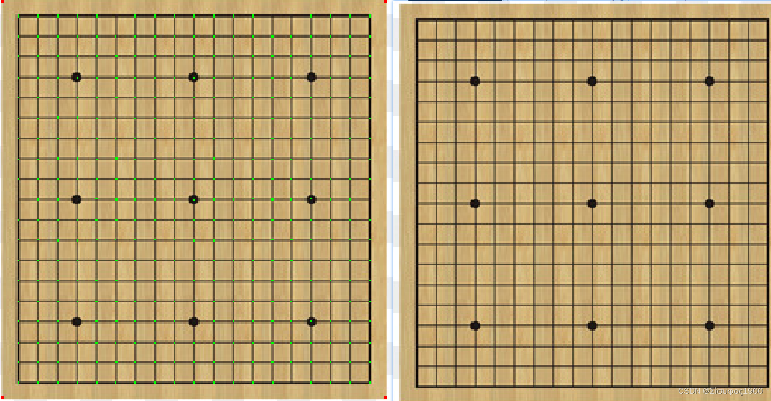
*检测棋盘格
read_image (Chese, 'D:/workplace/缺陷检测项目/chese.jpg')
get_image_size (Chese, Width4, Height4)
decompose3 (Chese, R, G, B)
mean_image (B, ImageMean1, 1, 1)
mean_image (B, ImageMean2, 5, 5)
dyn_threshold (ImageMean1, ImageMean2, RegionDynThresh1, 5, 'dark')
connection (RegionDynThresh1, ConnectedRegions6)
select_shape (ConnectedRegions6, SelectedRegions7, 'area', 'and', 30, 99999)

opening_rectangle1 (SelectedRegions7, RegionOpening5, 1, 13)

opening_rectangle1 (SelectedRegions7, RegionOpening6, 13, 1)
intersection (RegionOpening5, RegionOpening6, RegionIntersection1)
dev_display (Chese)
dev_display (RegionIntersection1)
七、油渍检测
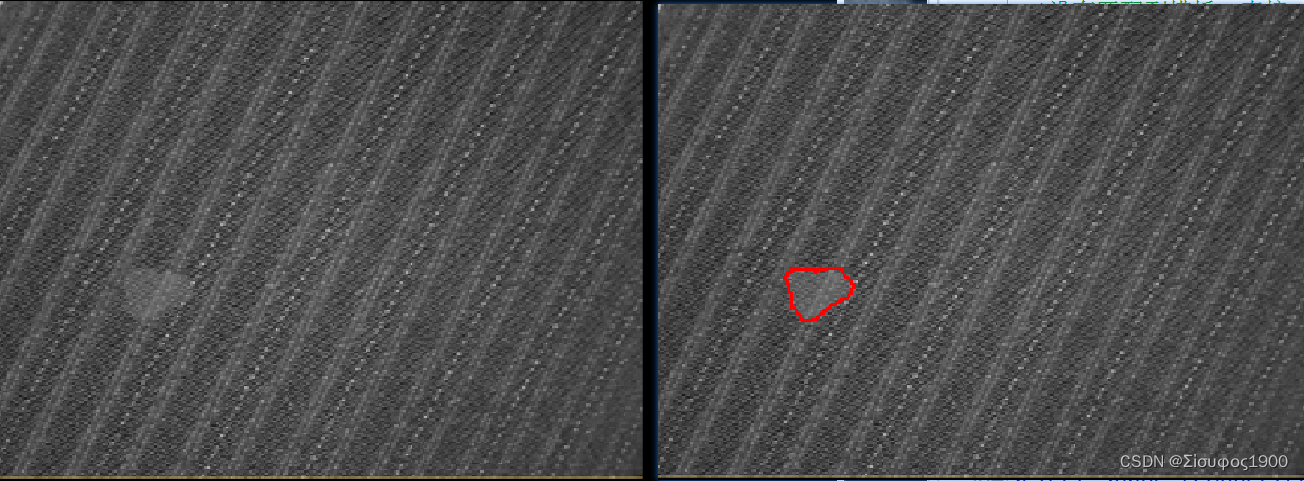
* 油渍测试
read_image (Image5, 'D:/workplace/缺陷检测项目/5.png')
decompose3 (Image5, R_image, B_image, G_image)
get_image_size (R_image, Width5, Height5)
rgb1_to_gray (Image5, GrayImage3)

gen_gauss_filter (GaussFilter1, 30, 30, 0, 'none', 'rft',Width5, Height5)
gen_gauss_filter (GaussFilter3, 3, 3, 0, 'none', 'rft',Width5, Height5)

sub_image (GaussFilter1, GaussFilter3, Filternew, 1, 0)

rft_generic (GrayImage3, ImageFFT2, 'to_freq', 'none', 'complex', Width5)
convol_fft (ImageFFT2, Filternew, ImageConvol2)
rft_generic (ImageConvol2, ImageFFTbackGround, 'from_freq', 'n', 'real', Width5)
threshold (ImageFFTbackGround, Region5, -26, -9)
connection (Region5, ConnectedRegions8)
select_shape (ConnectedRegions8, SelectedRegions9, 'area', 'and', 373.7, 959.2)
dev_display (Image5)
dev_display (SelectedRegions9)
八、点胶检测 溢胶 缺胶
dev_update_off ()
*
* Create the planar deformable model to align images with the
* reference contour
prepare_alignment (RegionPart, RowT, ColumnT, ModelID)
smallest_rectangle1 (RegionPart, PartRow1, PartColumn1, PartRow2, PartColumn2)
*
* Define the reference path of the adhesive beads. This path could
* also be generated by drawing it on a reference image with, e.g.,
* draw_xld.
gen_contour_nurbs_xld (ContourRef, [701.767,626.953,538.867,443.54,390.447,360.28,354.247,363.9,400.1,458.02,509.907,588.34,659.533,696.94], [319.24,336.133,367.507,431.46,489.38,546.093,646.247,722.267,776.567,826.04,869.48,912.92,934.64,929.813], 'auto', [15,15,15,15,15,15,15,15,15,15,15,15,15,15], 3, 1, 5)
*
* Create a new bead inspection model with the following parameters
TargetWidth := 14
WidthTolerance := 7
PositionTolerance := 30
Polarity := 'dark'
create_bead_inspection_model (ContourRef, TargetWidth, WidthTolerance, PositionTolerance, Polarity, [], [], BeadInspectionModel)
*
* Show a correct adhesive bead together with the reference contour
read_image (Image, 'bead/adhesive_bead_01')
align_bead (Image, ImageAligned, ModelID, RowT, ColumnT)
*
* Create two parallel contours to give an impression of how
* thick a correct adhesive bead should be
gen_parallel_contour_xld (ContourRef, ModelSide1, 'regression_normal', TargetWidth * 0.5)
gen_parallel_contour_xld (ContourRef, ModelSide2, 'regression_normal', -TargetWidth * 0.5)
concat_obj (ModelSide1, ModelSide2, ModelSides)
*
* Create two parallel contours to give an impression of where
* a correct adhesive bead should be located
gen_parallel_contour_xld (ContourRef, PositionToleranceSide1, 'regression_normal', PositionTolerance)
gen_parallel_contour_xld (ContourRef, PositionToleranceSide2, 'regression_normal', -PositionTolerance)
concat_obj (PositionToleranceSide1, PositionToleranceSide2, PositionToleranceSides)
dev_close_window ()
dev_open_window_fit_size (0, 0, PartColumn2 - PartColumn1 + 1, PartRow2 - PartRow1 + 41, -1, -1, WindowHandle)
set_display_font (WindowHandle, 16, 'mono', 'true', 'false')
dev_set_part (PartRow1 - 20, PartColumn1, PartRow2 + 20, PartColumn2)
dev_display (ImageAligned)
dev_set_line_width (2)
dev_set_color ('green')
dev_display (ContourRef)
dev_set_line_width (1)
dev_display (ModelSides)
dev_set_color ('yellow')
dev_display (PositionToleranceSides)
Message := 'Correct adhesive bead and the reference contour. The'
Message[1] := 'yellow contours indicate the range of position tolerance.'
dev_disp_text (Message, 'window', 12, 12, 'black', [], [])
dev_disp_text ('Press Run (F5) to continue', 'window', 'bottom', 'right', 'black', [], [])
stop ()
*
*
* Now, perform the inspection task
TextOffset := 20
NumImages := 7
for Index := 1 to NumImages by 1
    read_image (Image, 'bead/adhesive_bead_' + Index$'02')
    *
    * Align the input image with the reference image
    align_bead (Image, ImageAligned, ModelID, RowT, ColumnT)
    *
    * Apply the bead inspection model to the aligned image
    apply_bead_inspection_model (ImageAligned, LeftContour, RightContour, ErrorSegment, BeadInspectionModel, ErrorType)
    *
    * Display the segmented adhesive bead with its error segments
    set_window_param (WindowHandle, 'flush', 'false')
    dev_clear_window ()
    dev_display (ImageAligned)
    dev_set_line_width (1)
    dev_set_color ('white')
    dev_display (ContourRef)
    dev_display (ModelSides)
    dev_display (PositionToleranceSides)
    dev_set_line_width (2)
    dev_set_color ('green')
    dev_display (LeftContour)
    dev_display (RightContour)
    dev_set_color ('red')
    dev_display (ErrorSegment)
    if (|ErrorType| == 0)
        * No errors detected
        Message := 'Adhesive bead is OK'
        dev_disp_text (Message, 'window', 12, 12, 'white', 'box_color', 'forest green')
        dev_disp_text ('Press Run (F5) to continue', 'window', 'bottom', 'right', 'black', [], [])
        flush_buffer (WindowHandle)
        set_window_param (WindowHandle, 'flush', 'true')
        stop ()
    else
        * Display errors by error class
        Message[0] := 'Adhesive bead is not OK:'
        *
        ErrorClasses := ['no bead','too thin','too thick','incorrect position']
        for ClassIndex := 0 to |ErrorClasses| - 1 by 1
            Class := ErrorClasses[ClassIndex]
            ErrorIndices := find(ErrorType,Class)
            if (ErrorIndices != -1)
                select_obj (ErrorSegment, SelectedSegments, ErrorIndices + 1)
                dev_set_color ('red')
                dev_set_line_width (3)
                if (Class != 'no bead')
                    gen_display_segments (SelectedSegments, LeftContour, RightContour, ErrorParts)
                    dev_display (ErrorParts)
                else
                    dev_display (SelectedSegments)
                endif
                area_center_points_xld (SelectedSegments, Area, Row, Column)
                for E := 0 to |ErrorIndices| - 1 by 1
                    dev_disp_text (ErrorIndices[E] + 1, 'image', Row[E], Column[E] - TextOffset, 'white', 'box_color', 'red')
                    TextOffset := 20 - TextOffset
                endfor
            endif
        endfor
        dev_disp_text (Message, 'window', 12, 12, 'white', 'box_color', 'red')
        dev_disp_text ([1:|ErrorType|] + ': ' + ErrorType, 'image', 500, 500, 'red', 'box', 'false')
        if (Index < NumImages)
            dev_disp_text ('Press Run (F5) to continue', 'window', 'bottom', 'right', 'black', [], [])
            flush_buffer (WindowHandle)
            set_window_param (WindowHandle, 'flush', 'true')
            stop ()
        endif
    endif
endfor
flush_buffer (WindowHandle)
set_window_param (WindowHandle, 'flush', 'true')
九、镜片表面检测
read_image (Image7, 'D:/workplace/缺陷检测项目/7.png')
rgb1_to_gray (Image7, GrayImage4)
get_image_size (GrayImage4, Width6, Height6)
fft_generic (GrayImage4, ImageFFT3, 'to_freq', -1, 'sqrt', 'dc_center', 'complex')

*淹没竖直方向杂波  这里相当于是做了卷积 convol_fft()
gen_rectangle1 (ROI_0, 361.374, 7.58422, 387.065, 737.783)
paint_region (ROI_0, ImageFFT3, ImageResult, 0, 'fill')
*傅里叶变换 频域变换成空间域
fft_generic (ImageResult, ImageFFT1, 'from_freq', 1, 'sqrt', 'dc_center', 'byte')
threshold (ImageFFT1, Region6, 10, 255)
dev_display (Image7)
dev_display (Region6)
十、印刷品检测
思路
- create_variation_model —— 创建一个差异模型
- get_variation_model —— 获得差异模型
- train_variation_model —— 训练差异模型
- prepare_variation_model —— 准备差异模型
- compare_variation_model —— 比较模型与实例
- clear_variation_model —— 清除差异模型
算子解释:
create_variation_model
*创建一个差异模版
*Width 图像的宽
*Height
*Type: 'byte'整形
*Mode
    *'standard'表示标准的训练方法,标准图像的位置是各训练图像位置的平均,
    *'robust'表示鲁棒的训练方法,标准图像的位置是各训练图像的中值,此模式在训练图像中可能存在ERROR时使用,
    *'direct'表示标准图像由单张图像经过处理得到,由此方法得到的标准图像只能应用prepare_direct_variation_model算子得到variation model。
*VariationModelID
create_variation_model (Width, Height, 'byte', 'standard', VariationModelID)
prepare_variation_model
*prepare_variation_model( : : ModelID, AbsThreshold, VarThreshold : )
*设置variation model(差异模型)的绝对阈值 和 相对阈值。
  *绝对阈值 即 待检测图像与标准图像的差值,
  *相对阈值即待检测图像与variation model与VarThreshold乘积的差值。
prepare_variation_model (VariationModelID, 20, 3)
compare_variation_model
* 差分 (就是检查两幅图像相减,剩下的区域就是不同的地方了,与模板图像不同的地方就是缺陷)
         * 这里可不能用 difference 做差分啊,halcon为变形模板提供了专门的差分算子 : compare_variation_model
         *compare_variation_model(Image : Region : ModelID : )
         *待检测图像与variation model进行比较,超过阈值的区域在Rgion参数中返回。
         *同threshold一样,返回的区域被看做一个区域,可以使用connection算子进行连通性分析,然后根据区域的特征(如面积)对区域进行选择
        compare_variation_model (ImageReduced, RegionDiff, VariationModelID)
print_check.hdev
dev_update_off ()
read_image (Image, 'pen/pen-01')
get_image_size (Image, Width, Height)
dev_close_window ()
dev_open_window (0, 0, Width, Height, 'black', WindowHandle)
set_display_font (WindowHandle, 16, 'mono', 'true', 'false')
dev_set_color ('red')
dev_display (Image)
* Note: the shape model will be constructed from a ROI that is computed
* automatically based on a simple image segmentation.
threshold (Image, Region, 100, 255)
fill_up (Region, RegionFillUp)
difference (RegionFillUp, Region, RegionDifference)
shape_trans (RegionDifference, RegionTrans, 'convex')
dilation_circle (RegionTrans, RegionDilation, 8.5)
reduce_domain (Image, RegionDilation, ImageReduced)
inspect_shape_model (ImageReduced, ModelImages, ModelRegions, 1, 20)
gen_contours_skeleton_xld (ModelRegions, Model, 1, 'filter')
area_center (RegionDilation, Area, RowRef, ColumnRef)
* 目的是通过匹配来训练变形的轮廓
create_shape_model (ImageReduced, 5, rad(-10), rad(20), 'auto', 'none', 'use_polarity', 20, 10, ShapeModelID)
*创建一个变形模版
*Width 图像的宽
*Height
*Type: 'byte'整形
*Mode
*'standard'表示标准的训练方法,标准图像的位置是各训练图像位置的平均,
*'robust'表示鲁棒的训练方法,标准图像的位置是各训练图像的中值,此模式在训练图像中可能存在ERROR时使用,
*'direct'表示标准图像由单张图像经过处理得到,由此方法得到的标准图像只能应用prepare_direct_variation_model算子得到variation model。
*VariationModelID
create_variation_model (Width, Height, 'byte', 'standard', VariationModelID)
* 用这15张图像来训练变形模版
for I := 1 to 15 by 1
read_image (Image, 'pen/pen-' + I$'02d')
find_shape_model (Image, ShapeModelID, rad(-10), rad(20), 0.5, 1, 0.5, 'least_squares', 0, 0.9, Row, Column, Angle, Score)
if (|Score| == 1)
vector_angle_to_rigid (Row, Column, Angle, RowRef, ColumnRef, 0, HomMat2D)
affine_trans_image (Image, ImageTrans, HomMat2D, 'constant', 'false')
*将训练各种变形的模版
train_variation_model (ImageTrans, VariationModelID)
dev_display (ImageTrans)
dev_display (Model)
endif
endfor
stop ()
* 获得变形的模版的标准图像(MeanImage)和差异图像(VarImage)
get_variation_model (MeanImage, VarImage, VariationModelID)
*在做检测之前可以通过经验来对变形模版进行调参数
*prepare_variation_model( : : ModelID, AbsThreshold, VarThreshold : )
*设置variation model(差异模型)的绝对阈值 和 相对阈值。
*绝对阈值 即 待检测图像与标准图像的差值,
*相对阈值即待检测图像与variation model与VarThreshold乘积的差值。
prepare_variation_model (VariationModelID, 20, 3)
erosion_rectangle1 (RegionFillUp, RegionROI, 1, 15)
dev_display (MeanImage)
set_tposition (WindowHandle, 20, 20)
dev_set_color ('green')
write_string (WindowHandle, 'Reference image')
disp_continue_message (WindowHandle, 'black', 'true')
stop ()
dev_display (VarImage)
set_tposition (WindowHandle, 20, 20)
dev_set_color ('green')
write_string (WindowHandle, 'Variation image')
disp_continue_message (WindowHandle, 'black', 'true')
stop ()
*通过变形模版来进行匹配
dev_set_draw ('margin')
NumImages := 30
for I := 1 to 30 by 1
read_image (Image, 'pen/pen-' + I$'02d')
*这里用的还是那个正常的模版
find_shape_model (Image, ShapeModelID, rad(-10), rad(20), 0.5, 1, 0.5, 'least_squares', 0, 0.9, Row, Column, Angle, Score)
if (|Score| == 1)
vector_angle_to_rigid (Row, Column, Angle, RowRef, ColumnRef, 0, HomMat2D)
affine_trans_image (Image, ImageTrans, HomMat2D, 'constant', 'false')
*到那个位置
reduce_domain (ImageTrans, RegionROI, ImageReduced)
* 差分 (就是检查两幅图像相减,剩下的区域就是不同的地方了,与模板图像不同的地方就是缺陷)
* 这里可不能用 difference 做差分啊,halcon为变形模板提供了专门的差分算子 : compare_variation_model
*compare_variation_model(Image : Region : ModelID : )
*待检测图像与variation model进行比较,超过阈值的区域在Rgion参数中返回。
*同threshold一样,返回的区域被看做一个区域,可以使用connection算子进行连通性分析,然后根据区域的特征(如面积)对区域进行选择
compare_variation_model (ImageReduced, RegionDiff, VariationModelID)
*这个就是将差异分割
connection (RegionDiff, ConnectedRegions)
*
select_shape (ConnectedRegions, RegionsError, 'area', 'and', 20, 1000000)
count_obj (RegionsError, NumError)
dev_clear_window ()
dev_display (ImageTrans)
dev_set_color ('red')
dev_display (RegionsError)
set_tposition (WindowHandle, 20, 20)
if (NumError == 0)
dev_set_color ('green')
write_string (WindowHandle, 'Clip OK')
else
dev_set_color ('red')
write_string (WindowHandle, 'Clip not OK')
endif
endif
if (I < NumImages)
disp_continue_message (WindowHandle, 'black', 'true')
stop ()
endif
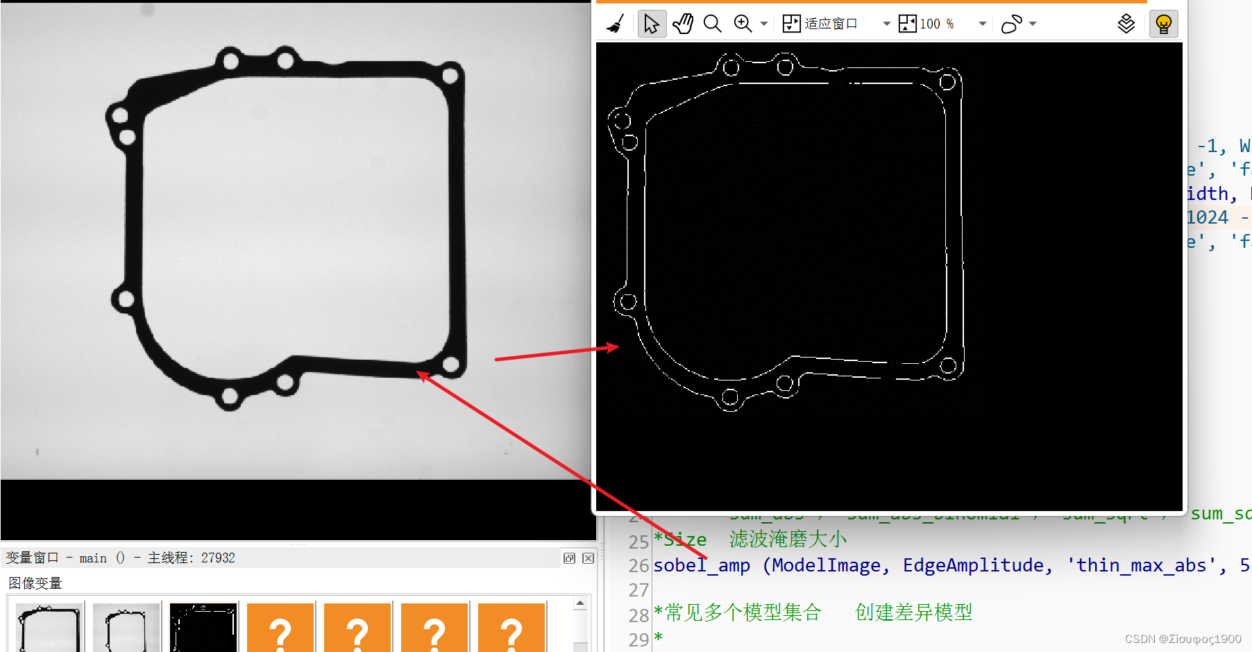
endfor十一、变形匹配+差分
算子解释:
sobel_amp
*使用Sobel算子检测边缘(幅度)
*Image     ModelImage 输入图像
*EdgeAmplitude  输出边缘图像
*FilterType    过滤器类型。
     *‘sum_abs’,‘sum_abs_binomial’,‘sum_sqrt’,‘sum_sqrt_binomial’,‘thin_max_abs’,‘thin_max_abs_binomial’,‘thin_sum_abs’,‘thin_sum_abs_binomial’,‘x’,‘x_binomial’,‘y’,'y_binomial
*Size  滤波淹磨大小
sobel_amp (ModelImage, EdgeAmplitude, 'thin_max_abs', 5)
create_variation_model
*创建一个差异模版
*Width 图像的宽
*Height
*Type: 'byte'整形
*Mode
    *'standard'表示标准的训练方法,标准图像的位置是各训练图像位置的平均,
    *'robust'表示鲁棒的训练方法,标准图像的位置是各训练图像的中值,此模式在训练图像中可能存在ERROR时使用,
    *'direct'表示标准图像由单张图像经过处理得到,由此方法得到的标准图像只能应用prepare_direct_variation_model算子得到variation model。
*VariationModelID
create_variation_model (425, 410, 'byte', 'direct', VariationModelID)
create_local_deformable_model
*create_local_deformable_model 创建局部变形匹配模板
    *参数列表:
    *Template  //输入多通道图像,用来创建model
    *NumLevels //金字塔层数:'auto', 0,1,2,3,。。。
    *AngleStart //输入起始角度(默认-0.39)
    *AngleExtent//角度旋转的范围(默认0.79)
    *AngleStep //旋转的步长,即分辨率,默认’auto'
    *ScaleRMin//行方向的最小缩放比例,默认1.0,通常大于0小于1
    *ScaleRMax//行方向的最大缩放比例,默认1.0,通常大于1小于1.5
    *ScaleRStep//行方向的缩放步长,可影响行方向的分辨率,默认'auto', 0.01,0.02,0.05,。。
    *ScaleCMin//
    *ScaleCMax//          列方向,同上
    *ScaleCStep//
    *Optimization//生成模型时的优化方式,默认'none'可选,'auto','point_reduction_XXX'
    *Metric//比较时候的标准,默认'use_polarity'使用极坐标系进行比较
    *Contrast//在模板图片的滤波或者磁滞滤波中,控制结果的对比度,默认'auto', 10, 20....
    *MinContrast//在搜寻对象过程中的最小对比度,默认'auto', 1, 2, 3, 5....
    *ParamName// 普通参数名字(不太清楚用途,后续研究)默认[], 'min_size','part_size'
                  *deformation_smoothness:平滑的度,对于变形越大参数越大
                  *expand_border:扩大ImageRecfified VectorField 区域
    *ParamValue//参数值, 默认[], 可选'small', 'medium', big'
    *ModelID// 输出的模型handle
create_local_deformable_model (ModelImage, 'auto', [], [], 'auto', 0.9, [], 'auto', 0.9, [], 'auto', 'none', 'use_polarity', 'auto', 'auto', [], [], ModelID)
get_deformable_model_contours
* Level决定了返回第几层金字塔图像的边缘
get_deformable_model_contours (ModelContours, ModelID, 1)
dev_update_off ()
Smoothness := 25
read_image (ModelImage, 'gasket/gasket_model')
read_image (Image, 'gasket/gasket_01')
dev_close_window ()
dev_open_window_fit_image (ModelImage, 0, 0, 500, -1, WindowHandle1)
set_display_font (WindowHandle1, 16, 'mono', 'true', 'false')
get_window_extents (WindowHandle1, Row, Column, Width, Height)
dev_open_window_fit_image (Image, 0, Width + 12, 1024 - Width - 36, -1, WindowHandle2)
set_display_font (WindowHandle2, 16, 'mono', 'true', 'false')
*
* Create variation model
*使用Sobel算子检测边缘(幅度)
*Image ModelImage 输入图像
*EdgeAmplitude 输出边缘图像
*FilterType 过滤器类型。
*‘sum_abs’,‘sum_abs_binomial’,‘sum_sqrt’,‘sum_sqrt_binomial’,‘thin_max_abs’,‘thin_max_abs_binomial’,‘thin_sum_abs’,‘thin_sum_abs_binomial’,‘x’,‘x_binomial’,‘y’,'y_binomial
*Size 滤波淹磨大小
sobel_amp (ModelImage, EdgeAmplitude, 'thin_max_abs', 5)
*常见多个模型集合 创建差异模型
*创建一个差异模版
*Width 图像的宽
*Height
*Type: 'byte'整形
*Mode
*'standard'表示标准的训练方法,标准图像的位置是各训练图像位置的平均,
*'robust'表示鲁棒的训练方法,标准图像的位置是各训练图像的中值,此模式在训练图像中可能存在ERROR时使用,
*'direct'表示标准图像由单张图像经过处理得到,由此方法得到的标准图像只能应用prepare_direct_variation_model算子得到variation model。
*VariationModelID
create_variation_model (425, 410, 'byte', 'direct', VariationModelID)
*准备参数 直接设参数+标准图像+边缘幅度图像
prepare_direct_variation_model (ModelImage, EdgeAmplitude, VariationModelID, 30, 1.5)
*
* Create locally deformable model
*create_local_deformable_model 创建局部变形匹配模板
*参数列表:
*Template //输入多通道图像,用来创建model
*NumLevels //金字塔层数:'auto', 0,1,2,3,。。。
*AngleStart //输入起始角度(默认-0.39)
*AngleExtent//角度旋转的范围(默认0.79)
*AngleStep //旋转的步长,即分辨率,默认’auto'
*ScaleRMin//行方向的最小缩放比例,默认1.0,通常大于0小于1
*ScaleRMax//行方向的最大缩放比例,默认1.0,通常大于1小于1.5
*ScaleRStep//行方向的缩放步长,可影响行方向的分辨率,默认'auto', 0.01,0.02,0.05,。。
*ScaleCMin//
*ScaleCMax// 列方向,同上
*ScaleCStep//
*Optimization//生成模型时的优化方式,默认'none'可选,'auto','point_reduction_XXX'
*Metric//比较时候的标准,默认'use_polarity'使用极坐标系进行比较
*Contrast//在模板图片的滤波或者磁滞滤波中,控制结果的对比度,默认'auto', 10, 20....
*MinContrast//在搜寻对象过程中的最小对比度,默认'auto', 1, 2, 3, 5....
*ParamName// 普通参数名字(不太清楚用途,后续研究)默认[], 'min_size','part_size'
*deformation_smoothness:平滑的度,对于变形越大参数越大
*expand_border:扩大ImageRecfified VectorField 区域
*ParamValue//参数值, 默认[], 可选'small', 'medium', big'
*ModelID// 输出的模型handle
create_local_deformable_model (ModelImage, 'auto', [], [], 'auto', 0.9, [], 'auto', 0.9, [], 'auto', 'none', 'use_polarity', 'auto', 'auto', [], [], ModelID)
* Level决定了返回第几层金字塔图像的边缘
get_deformable_model_contours (ModelContours, ModelID, 1)
area_center (ModelImage, Area, Row, Column)
hom_mat2d_identity (HomMat2DIdentity)
hom_mat2d_translate (HomMat2DIdentity, Row, Column, HomMat2DTranslate)
affine_trans_contour_xld (ModelContours, ContoursAffineTrans, HomMat2DTranslate)
dev_set_window (WindowHandle1)
dev_set_line_width (2)
dev_set_color ('yellow')
dev_display (ModelImage)
dev_display (ContoursAffineTrans)
disp_message (WindowHandle1, 'Model image and contours', 'window', 12, 12, 'black', 'true')
disp_continue_message (WindowHandle1, 'black', 'true')
stop ()
*
* Process images iteratively
NumImages := 7
for Index := 1 to NumImages by 1
read_image (Image, 'gasket/gasket_' + Index$'02')
dev_set_window (WindowHandle2)
dev_display (Image)
disp_message (WindowHandle2, 'Search ...', 'window', 12, 12, 'black', 'true')
* Find the model in the search image.
* As result, the rectified image, the respective
* vector field, and the found contours are queried.
count_seconds (S1)
* 寻找
find_local_deformable_model (Image, ImageRectified, VectorField, DeformedContours, ModelID, rad(-10), rad(20), 1, 1, 1, 1, 0.93, 1, 0.7, 0, 0.4, ['image_rectified','vector_field','deformed_contours'], ['deformation_smoothness','expand_border','subpixel'], [Smoothness,0,1], Score, Row, Column)
count_seconds (S2)
Time := S2 - S1
if (|Score| > 0)
*生成变形网格
gen_warped_mesh_region (VectorField, MeshRegion, Smoothness)
gen_region_contour_xld (DeformedContours, EdgeRegion, 'margin')
dilation_circle (EdgeRegion, RegionDilation, 2 * Smoothness)
intersection (RegionDilation, MeshRegion, RegionIntersection)
dev_set_line_width (1)
dev_set_color ('yellow')
dev_display (RegionIntersection)
Found[Index] := |Score|
dev_set_line_width (2)
dev_set_color ('green')
dev_display (DeformedContours)
disp_message (WindowHandle2, ['Match found in ' + Time$'1.2f' + ' s','Score: ' + Score$'.2f'], 'window', 12, 12, 'black', 'true')
dev_set_window (WindowHandle1)
dev_display (ImageRectified)
*将匹配的区域和变形模版区域 的进行对比
compare_variation_model (ImageRectified, Region, VariationModelID)
connection (Region, ConnectedRegions)
*寻找区域
select_shape (ConnectedRegions, SelectedRegions, 'area', 'and', 40, 99999)
count_obj (SelectedRegions, Number)
* 显示
if (Number > 0)
area_center (SelectedRegions, Area, Row1, Column1)
elliptic_axis (SelectedRegions, Ra, Rb, Phi)
tuple_gen_const (Number, 1, Ones)
PointOrder := []
for Idx := 0 to Number - 1 by 1
PointOrder := [PointOrder,'positive']
endfor
gen_ellipse_contour_xld (ContEllipse, Row1, Column1, Phi, Ra + 10, Rb + 10, 0 * Ones, 6.28318 * Ones, PointOrder, 1.5)
dev_set_color ('red')
dev_display (ContEllipse)
disp_message (WindowHandle1, 'Part not OK!', 'window', 12, 12, 'red', 'true')
else
disp_message (WindowHandle1, 'Part OK', 'window', 12, 12, 'forest green', 'true')
endif
else
disp_message (WindowHandle2, 'Nothing found', 'window', 12, 12, 'black', 'true')
endif
if (Index < NumImages)
disp_continue_message (WindowHandle2, 'black', 'true')
stop ()
endif
endfor


 1473
1473

 被折叠的 条评论
为什么被折叠?
被折叠的 条评论
为什么被折叠?
 到【灌水乐园】发言


