


一、概述
这种标定有两种模式,有一个标定板和多个标定板两种
一个标定板
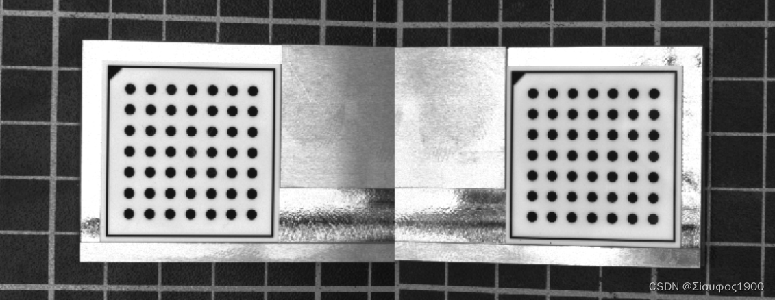
两个相机的重叠区域比较大,那么我们可以把标定板放到那个重叠区域来统一坐标系,如下
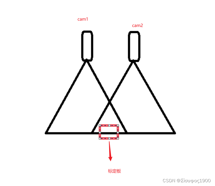
这种是只需要一个标定板,这种是推荐的方式 。这种是比较简单的,今天主要看的第二种
多个标定板
由于要求的视野没有重叠区域,或者重叠的区域太小了,那么我们可以采用这种方式
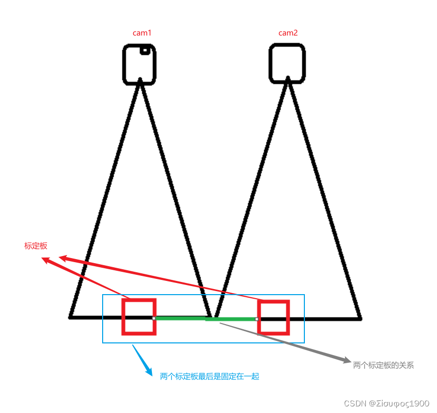
这个方法就是对上面绿色的部分,两个标定板的关系很重要,会直接影响到最后的图像结果
二、算法分析
halcon例程:双相机标定进行高精度对象镶嵌-工业视觉/halcon-少有人走的路
1、相机标定
单独标定连个相机Cam1 Cam2
*两个相机的内参 之前已经标定过了
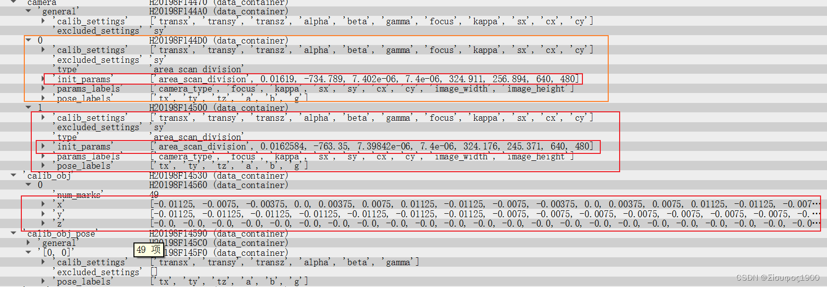
gen_cam_par_area_scan_division (0.01619, -734.789, 7.402e-006, 7.4e-006, 324.911,\
256.894, 640, 480, CamParam1)
gen_cam_par_area_scan_division (0.0162584, -763.35, 7.39842e-006, 7.4e-006, 324.176,\
245.371, 640, 480, CamParam2)
* 
2、获得姿态Pose
获得各自标定板在各自相机的字体
* 通过相机的内参来而且拍在两个相机中拍同一个标定板
CaltabName := 'caltab_30mm.descr'
*标定参数
*2 表示的是两个相机
* 表示的是只有一个物体object ,这里是指只有一个标定板
create_calib_data ('calibration_object', 2, 1, CalibDataID)
*设置标定参数
set_calib_data_calib_object (CalibDataID, 0, CaltabName)
set_calib_data_cam_param (CalibDataID, 0, [], CamParam1)
set_calib_data_cam_param (CalibDataID, 1, [], CamParam2)
*
* Find and display the calibration plate in the images.
dev_set_window (WindowHandle1)
find_calib_object (Image1, CalibDataID, 0, 0, 0, [], [])
* 这一步很重要,重要就在计算的那个Pose 表示在相机1 下的姿态
* get_calib_data_observ_points( : : CalibDataID, CameraIdx, CalibObjIdx, CalibObjPoseIdx : Row, Column, Index, Pose)功能:从标定数据模型中提取标记点坐标。
* 参数1:CalibDataID:标定数据模型句柄;
* 参数2:CameraIdx:摄像机索引,默认值为0;
* 参数3:CalibObjIdx:标定板索引,默认值0;
* 参数4:CalibObjPoseIdx:观察到的标定板位姿的索引;
* 参数1:( Row, Column):检测到的标记点坐标;
* 参数2: Index:检测到的点与观测到的标定板上的点的对应关系。
* 参数3: Pose:粗略估计观测到的标定板相对于观测相机的姿态。
get_calib_data_observ_points (CalibDataID, 0, 0, 0, RowCoord1, ColumnCoord1, Index1, Pose1)
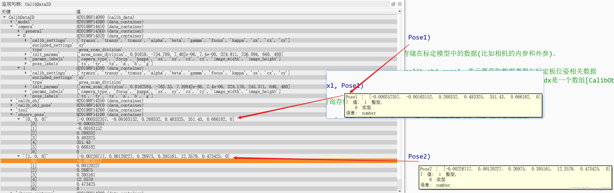
* get_calib_data( : : CalibDataID, ItemType, ItemIdx, DataName : DataValue):查询存储在标定模型中的数据(比如相机的内参和外参)。
* 控制输入参数1:CalibDataID:标定数据模型句柄;
* 控制输入参数2:ItemType:数据类型,'camera':表示要获取数据类型是与摄像机相关数据; 'calib_obj_pose':表示要获取数据类型与标定板位姿相关数据
* 控制输入参数3:ItemIdx:ItemIdx:输入参数,ItemType='camera'时,ItemIdx表示摄像机索引;ItemType='calib_obj_pose'时,ItemIdx是一个数组[CalibObjIdx, CalibObjPoseIdx],其中CalibObjIdx表示标定板索引,CalibObjPoseIdx表示参考位姿的图像索引;
* 控制输入参数4:DataName:输入要查询的属性名,'params'表示摄像机内参数; 'pose'表示摄像机外参数;
gen_cross_contour_xld (Cross, RowCoord1, ColumnCoord1, 6, 0.785398)
get_calib_data_observ_contours (Caltab1, CalibDataID, 'caltab', 0, 0, 0)
dev_display (Caltab1)
*
dev_set_window (WindowHandle2)
find_calib_object (Image2, CalibDataID, 1, 0, 0, [], [])
* 这一步很重要,重要就在计算的那个Pose 表示在相机2 下的姿态
get_calib_data_observ_points (CalibDataID, 1, 0, 0, RowCoord2, ColumnCoord2, Index2, Pose2)
gen_cross_contour_xld (Cross2, RowCoord2, ColumnCoord2, 6, 0.785398)
get_calib_data_observ_contours (Caltab2, CalibDataID, 'caltab', 1, 0, 0)
dev_display (Caltab2)此时标定板的情况如下:
3、设置标定板等的厚度
*标定板的厚度     为什么要除以1000
ThicknessCaliper := 2.9 / 1000.0
*平台的厚度
ThicknessPlate := 5.65 / 1000.0
*DiffHeight=先还原到基准面(+ThicknessCaliper)然后再加上要测量的产品的高度(-ThicknessPlate)=ThicknessPlate-ThicknessCaliper
DiffHeight := ThicknessPlate - ThicknessCaliper
*
4、设置裁剪图像以及在不同方向上的差
这个是在宏观意义的,这里只是画一个示意图
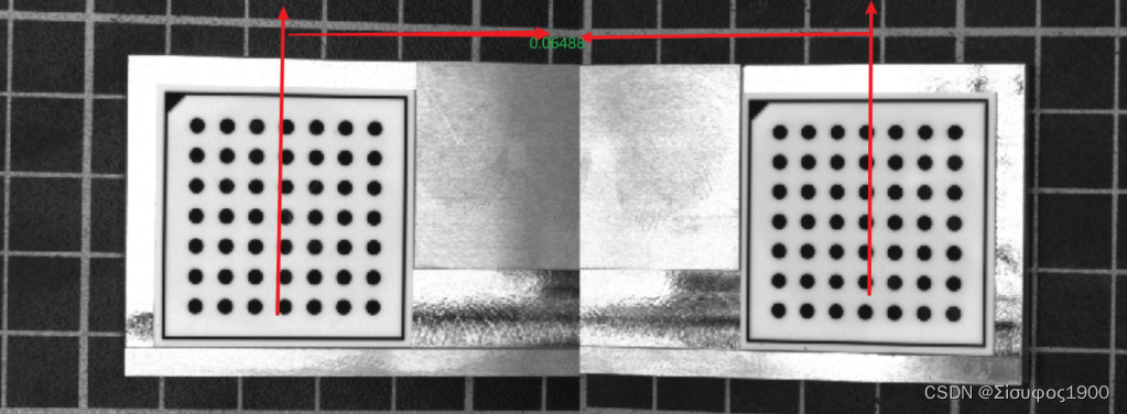
第一个标定和第二个标定板之间的间距如下
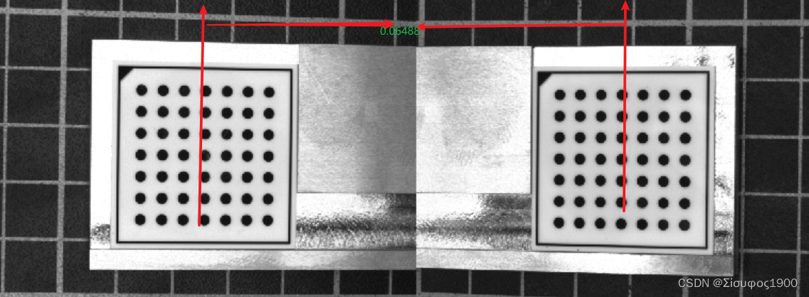
*=================================================================================================================================
*DistancePlates 表示连个标定板之间的距离
DistancePlates := 0.06488
*定义马赛克图像的像素大小(以米为单位)。
PixelSize := 0.0001
*
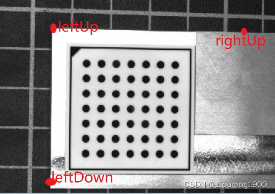
*第一(左)图像,确定必要的转变的姿势很简单。
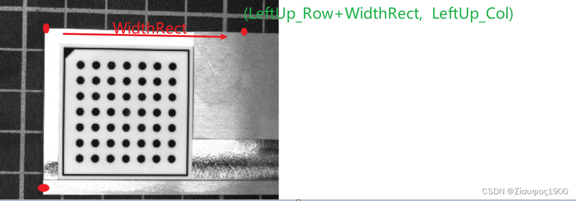
*您可以根据预先选择的边框宽度在图像坐标中定义校正图像的左上角
BorderInPercent := 3
get_image_size (Image1, WidthImage1, HeightImage1)
* gen_cross_contour_xld (Cross1, HeightImage1, WidthImage1,600, 0.785398)
* 图片中左上角的点
UpperRow := HeightImage1 * BorderInPercent / 100.0
LeftColumn := WidthImage1 * BorderInPercent / 100.0
*然后,这个点必须转换成世界坐标。
* image_points_to_world_plane( : : CameraParam, WorldPose, Rows, Cols, Scale : X, Y):将图像点变换到世界坐标系的z=0平面中,
* 并返回它们在3D坐标中的X和Y值。
* Map1 输出隐射
* 控制输入参数1: CameraParam:相机内参;
* 控制输入参数2:WorldPose:相机坐标系中世界坐标系的三维姿态(相机外参);
* 控制输入参数3: (Rows, Cols):待转换点的坐标;
* 控制输入参数4:Scale:比例或尺寸,Default value: 'm';
* 控制输出参数:X:世界坐标系中点的X坐标;
* 控制输出参数:Y:世界坐标系中点的Y坐标。
image_points_to_world_plane (CamParam1, Pose1, UpperRow, LeftColumn, 'm', Left_Up_X, Left_Up_Y)
* 为了确定校正图像的高度,我们需要定义一个位于第一个图像的下边界附近的点。
*左下角的点
LowerRow := HeightImage1 * (100 - BorderInPercent) / 100.0
LeftColumn := WidthImage1 * BorderInPercent / 100.0
*同样,这一点必须转换成世界坐标系。
image_points_to_world_plane (CamParam1, Pose1, LowerRow, LeftColumn, 'm', Left_Down_X, Left_Down_Y)
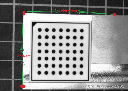
*高度可以确定为左上点和靠近下图像边界的点之间的垂直距离,以校正图像的像素表示。
HeightRect := int((Left_Down_Y - Left_Up_Y) / PixelSize)
*类似地,宽度可以由位于两个图像的重叠区域中的一个点来确定,在第一张图片的右边界附近。
OverlapInPercent := 10
RightColumn := WidthImage1 * (100 - OverlapInPercent / 2.0) / 100.0
image_points_to_world_plane (CamParam1, Pose1, UpperRow, RightColumn, 'm', Left_Right_X, Left_Right_Y)
WidthRect := int((Left_Right_X - Left_Up_X) / PixelSize)
* 具体示意图如下
* X --------------WidthRect-------------- X
* |
* |
* |
* |
*HeightRect
* |
* |
* |
* |
* |
* X
*============================================================================================================================5、计算第二张图像的拼接位置
                              WidthRect, HeightRect, PixelSize, 'bilinear')
*
* Generate a new homogeneous transformation matrix.
*生成一个新的齐次变换矩阵。
hom_mat3d_identity (HomMat3DIdentity)
*
* The second image must be rectified such that it fits exactly
* to the right of the first rectified image. This means that the
* upper left corner of the second rectified image must be identical
* with the upper right corner of the first rectified image.
* Therefore, we need to know the coordinates of the upper right corner
* of the first rectified image in the coordinate system that is defined
* by the calibration plate in the second image.
* First, we express the upper right corner of the first rectified image
* in the world coordinate system that is defined by the calibration plate
* in the first image. It can be determined by a transformation from
* the origin into the upper left corner of the
* first rectified image (a translation) followed by a translation along
* the upper border of the first rectified image. Together with the shift
* that compensates the thickness of the calibration plate, this
* transformation is represented by the homogeneous transformation matrix:
*第二幅图像必须校正,使其正好适合第一幅校正图像的右侧。
*这意味着第二校正图像的左上角必须与第一校正图像的右上角相同。
*因此,我们需要知道第一个校正图像的右上角在由第二个图像中的校准板定义的坐标系中的坐标。
*首先,我们在世界坐标系中表示第一幅校正图像的右上角,该坐标系由第一幅图像中的校准板定义。
*它可以通过从原点到第一校正图像的左上角的变换(平移)以及沿着第一校正图像的上边界的平移来确定。
*与补偿校准板厚度的位移一起,该变换由齐次变换矩阵表示:
second:=Left_Up_X + PixelSize * WidthRect


* 第二张图的拼接位置  具体示意图如下
*              first Image                        second Image
 *  Left_Up_X ----------------------PixelSize * WidthRect---------X----------------------
 *   |                                          |
 *   |                                          |
 *   |                                          |
 *   |                                          |
 *   |                                          |
 *HeightRect                                    |
 *   |                                          |
 *   |                                          |
 *   |                                          |
 *   |                                          |
 *   |                                          |
 *   X                                          |

hom_mat3d_translate_local (HomMat3DIdentity, Left_Up_X + PixelSize * WidthRect, Left_Up_Y, DiffHeight, cp1Hur1)
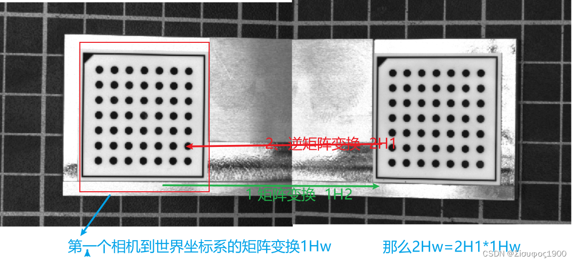
6、第二相机和第一个相机的关系
7、姿态转变矩阵计算
主要是为了得到第二个相机到世界坐标系之间的矩阵变换
DistancePlates是基于第一个相机(0,0,0)到第二个相机的关系
这个就是很简单了,最重要的一步就算完了
get_image_size (Image1, Width1, Height1)
DistancePlates:=0.06488
*DistancePlates:= WidthRect*PixelSize
*DistancePlates 是第一个相机-》第二个相机的矩阵 只是个X方向的移动  1H2
hom_mat3d_translate_local (HomMat3DIdentity, DistancePlates, 0, 0, cp1Hcp2)
*
* Then, we need the transformation between the two calibration plates of
* the calibration object. The homogeneous transformation matrix cp1Hcp2
* describes how the world coordinate system defined by the calibration plate
* in the first image is transformed into the world coordinate system
* defined by the calibration plate in the second image. This transformation
* must be known beforehand from a precise measurement of the calibration object.
* From these two transformations, it is easy to derive
* the transformation that transforms the world coordinate system
* of the second image such that its origin lies in the upper left corner
* of the second rectified image. For this, the two transformations
* have to be combined appropriately.
*然后,我们需要校准对象的两个校准板之间的转换。
*齐次变换矩阵cp1Hcp2描述如何将第一图像中校准板定义的世界坐标系转换为第二图像中校准板定义的世界坐标系。
*这种转换必须事先从校准对象的精确测量中得知。
*从这两个变换,很容易导出变换第二图像的世界坐标系的变换,使得其原点位于第二校正图像的左上角。
*为此,必须将这两个转换适当地结合起来。
*从第二个相机-》第一个相机的比那换
*1H2-》2H1
hom_mat3d_invert (cp1Hcp2, cp2Hcp1)
*相机2-》世界坐标   =2H1*1He  计算从相机二坐标到世界坐标的Pose 转换
hom_mat3d_compose (cp2Hcp1, cp1Hur1, cp2Hul2)
*
* With this, the pose of the calibration plate in the second image
* can be modified such that the origin of the world coordinate system
* lies in the upper left corner of the second rectified image.
*这样,可以修改第二图像中校准板的姿态,使得世界坐标系的原点位于第二校正图像的左上角。
*和上面的同一个道理
pose_to_hom_mat3d (Pose2, cam2Hcp2)
hom_mat3d_compose (cam2Hcp2, cp2Hul2, cam2Hul2)
hom_mat3d_to_pose (cam2Hul2, PoseNewOrigin2)
*
* With the resulting new pose and the size of the rectified image,
* which can be the same as for the first rectified image,
* the rectification map for the second image can be derived.
*根据得到的新姿势和校正图像的大小(其可以与第一校正图像相同),可以导出第二图像的校正地图。
8、生成映射
我们前面算这么多都是为了拿到各个相机的映射,如果是三个相机就是三个映射,四个相机就是4个映射
gen_image_to_world_plane_map (MapSingle2, CamParam2,\
                              PoseNewOrigin2, Width, Height,\
                              WidthRect, HeightRect, PixelSize, 'bilinear')
9、贴图
三、代码与效果
*示例程序展示了如何用校准的相机实现高精度的拼接。
*进一步的信息可以在解决方案指南III-C 3D视觉,第9章和第10章中找到。
*本示例程序在第9章中用于说明校准镶嵌。
* 前提,那个标定板放在两个产品的中间,而且两个相机的视野中都能看到完整的标定板
dev_update_off ()
ImgPath := '3d_machine_vision/multiple_cameras/'
*
* Open two windows for the left and the right image.
dev_close_window ()
read_image (Image1, ImgPath + 'camera1_ref')
get_image_size (Image1, Width, Height)
WindowScale := 0.66
dev_open_window (0, 0, Width * WindowScale, Height * WindowScale, 'black', WindowHandle1)
dev_open_window (0, Width * WindowScale + 6, Width * WindowScale, Height * WindowScale,'black', WindowHandle2)
*
* Set some parameters for both windows.
dev_set_window (WindowHandle1)
dev_set_color ('green')
dev_set_draw ('margin')
dev_set_line_width (2)
dev_set_part (0, 0, Height - 1, Width - 1)
set_display_font (WindowHandle1, 16, 'mono', 'true', 'false')
*
dev_set_window (WindowHandle2)
dev_set_color ('green')
dev_set_draw ('margin')
dev_set_line_width (2)
dev_set_part (0, 0, Height - 1, Width - 1)
set_display_font (WindowHandle2, 16, 'mono', 'true', 'false')
*
*两个相机的内参  之前已经标定过了
gen_cam_par_area_scan_division (0.01619, -734.789, 7.402e-006, 7.4e-006, 324.911,\
                                256.894, 640, 480, CamParam1)
gen_cam_par_area_scan_division (0.0162584, -763.35, 7.39842e-006, 7.4e-006, 324.176,\
                                245.371, 640, 480, CamParam2)
*
* Read the images and display them.
read_image (Image1, ImgPath + 'camera1_ref')
read_image (Image2, ImgPath + 'camera2_ref')
dev_set_window (WindowHandle1)
dev_display (Image1)
dev_set_window (WindowHandle2)
dev_display (Image2)
*
* 通过相机的内参来而且拍在两个相机中拍同一个标定板
CaltabName := 'caltab_30mm.descr'
*标定参数
*2 表示的是两个相机
* 表示的是只有一个物体object ,这里是指只有一个标定板
create_calib_data ('calibration_object', 2, 1, CalibDataID)


*设置标定参数
set_calib_data_calib_object (CalibDataID, 0, CaltabName)


set_calib_data_cam_param (CalibDataID, 0, [], CamParam1)
set_calib_data_cam_param (CalibDataID, 1, [], CamParam2)
*
* Find and display the calibration plate in the images.
dev_set_window (WindowHandle1)
find_calib_object (Image1, CalibDataID, 0, 0, 0, [], [])
* 这一步很重要,重要就在计算的那个Pose 表示在相机1 下的姿态

*      get_calib_data_observ_points( : : CalibDataID, CameraIdx, CalibObjIdx, CalibObjPoseIdx : Row, Column, Index, Pose)功能:从标定数据模型中提取标记点坐标。
*      参数1:CalibDataID:标定数据模型句柄;
*      参数2:CameraIdx:摄像机索引,默认值为0;
*      参数3:CalibObjIdx:标定板索引,默认值0;
*      参数4:CalibObjPoseIdx:观察到的标定板位姿的索引;
*      参数1:( Row, Column):检测到的标记点坐标;
*      参数2: Index:检测到的点与观测到的标定板上的点的对应关系。
*      参数3: Pose:粗略估计观测到的标定板相对于观测相机的姿态。
get_calib_data_observ_points (CalibDataID, 0, 0, 0, RowCoord1, ColumnCoord1, Index1, Pose1)

*    get_calib_data( : : CalibDataID, ItemType, ItemIdx, DataName : DataValue):查询存储在标定模型中的数据(比如相机的内参和外参)。
*    控制输入参数1:CalibDataID:标定数据模型句柄;
*    控制输入参数2:ItemType:数据类型,'camera':表示要获取数据类型是与摄像机相关数据; 'calib_obj_pose':表示要获取数据类型与标定板位姿相关数据
*    控制输入参数3:ItemIdx:ItemIdx:输入参数,ItemType='camera'时,ItemIdx表示摄像机索引;ItemType='calib_obj_pose'时,ItemIdx是一个数组[CalibObjIdx, CalibObjPoseIdx],其中CalibObjIdx表示标定板索引,CalibObjPoseIdx表示参考位姿的图像索引;
*    控制输入参数4:DataName:输入要查询的属性名,'params'表示摄像机内参数;  'pose'表示摄像机外参数;
gen_cross_contour_xld (Cross, RowCoord1, ColumnCoord1, 6, 0.785398)
get_calib_data_observ_contours (Caltab1, CalibDataID, 'caltab', 0, 0, 0)
dev_display (Caltab1)
*
dev_set_window (WindowHandle2)
find_calib_object (Image2, CalibDataID, 1, 0, 0, [], [])
* 这一步很重要,重要就在计算的那个Pose 表示在相机2 下的姿态
get_calib_data_observ_points (CalibDataID, 1, 0, 0, RowCoord2, ColumnCoord2, Index2, Pose2)
gen_cross_contour_xld (Cross2, RowCoord2, ColumnCoord2, 6, 0.785398)
get_calib_data_observ_contours (Caltab2, CalibDataID, 'caltab', 1, 0, 0)
dev_display (Caltab2)
*


* 同一个标定板在不同的相机坐标系下有两个不同的姿态,但是在世界坐标系下两个姿态表示的是同一个东西,同一个姿态。那么这个就是多相机标定的桥梁


disp_message (WindowHandle1, 'Calibration successful', 'window', 12, 12, 'black', 'true')
disp_continue_message (WindowHandle1, 'black', 'true')
stop ()
clear_calib_data (CalibDataID)


*
* Determine the offset between the calibration plate surface
* and the object surface
* 确定标定板表面与目标表面之间的偏移量


*标定板的厚度     为什么要除以1000
ThicknessCaliper := 2.9 / 1000.0
*平台的厚度
ThicknessPlate := 5.65 / 1000.0
*DiffHeight=先还原到基准面(+ThicknessCaliper)然后再加上要测量的产品的高度(-ThicknessPlate)=ThicknessPlate-ThicknessCaliper
DiffHeight := ThicknessPlate - ThicknessCaliper
*
*=================================================================================================================================
*DistancePlates 表示连个标定板之间的距离
DistancePlates := 0.06488
*定义马赛克图像的像素大小(以米为单位) 像素当量
PixelSize := 0.0001
*
*第一(左)图像,确定必要的转变的姿势很简单。
*您可以根据预先选择的边框宽度在图像坐标中定义校正图像的左上角
BorderInPercent := 3
get_image_size (Image1, WidthImage1, HeightImage1)
* gen_cross_contour_xld (Cross1, HeightImage1,  WidthImage1,600, 0.785398)

* 图片中左上角的点
UpperRow := HeightImage1 * BorderInPercent / 100.0
LeftColumn := WidthImage1 * BorderInPercent / 100.0
*然后,这个点必须转换成世界坐标。
*     image_points_to_world_plane( : : CameraParam, WorldPose, Rows, Cols, Scale : X, Y):将图像点变换到世界坐标系的z=0平面中,
    *                        并返回它们在3D坐标中的X和Y值。
    *     Map1 输出隐射
    *     控制输入参数1: CameraParam:相机内参;
    *     控制输入参数2:WorldPose:相机坐标系中世界坐标系的三维姿态(相机外参);
    *     控制输入参数3: (Rows, Cols):待转换点的坐标;
    *     控制输入参数4:Scale:比例或尺寸,Default value: 'm';
    *     控制输出参数:X:世界坐标系中点的X坐标;
    *     控制输出参数:Y:世界坐标系中点的Y坐标。
image_points_to_world_plane (CamParam1, Pose1, UpperRow, LeftColumn, 'm', Left_Up_X, Left_Up_Y)
* 为了确定校正图像的高度,我们需要定义一个位于第一个图像的下边界附近的点。

*左下角的点
LowerRow := HeightImage1 * (100 - BorderInPercent) / 100.0
LeftColumn := WidthImage1 * BorderInPercent / 100.0


*同样,这一点必须转换成世界坐标系。
image_points_to_world_plane (CamParam1, Pose1, LowerRow, LeftColumn, 'm', Left_Down_X, Left_Down_Y)
*高度可以确定为左上点和靠近下图像边界的点之间的垂直距离,以校正图像的像素表示。
HeightRect := int((Left_Down_Y - Left_Up_Y) / PixelSize)


*类似地,宽度可以由位于两个图像的重叠区域中的一个点来确定,在第一张图片的右边界附近。
OverlapInPercent := 10
RightColumn := WidthImage1 * (100 - OverlapInPercent / 2.0) / 100.0
image_points_to_world_plane (CamParam1, Pose1, UpperRow, RightColumn, 'm', Left_Right_X, Left_Right_Y)
WidthRect := int((Left_Right_X - Left_Up_X) / PixelSize)


* 具体示意图如下
 *    X --------------WidthRect-------------- X
 *   |
 *   |
 *   |
 *   |
 *HeightRect
 *   |
 *   |
 *   |
 *   |
 *   |
 *  X

*============================================================================================================================
*利用变换后的姿态和校正后图像的大小,可以得到第一幅图像的校正图。
set_origin_pose (Pose1, Left_Up_X, Left_Up_Y, DiffHeight, PoseNewOrigin1)

*
gen_image_to_world_plane_map (MapSingle1, CamParam1, PoseNewOrigin1, Width, Height, \
                              WidthRect, HeightRect, PixelSize, 'bilinear')
*
* Generate a new homogeneous transformation matrix.
*生成一个新的齐次变换矩阵。
hom_mat3d_identity (HomMat3DIdentity)
*
* The second image must be rectified such that it fits exactly
* to the right of the first rectified image. This means that the
* upper left corner of the second rectified image must be identical
* with the upper right corner of the first rectified image.
* Therefore, we need to know the coordinates of the upper right corner
* of the first rectified image in the coordinate system that is defined
* by the calibration plate in the second image.
* First, we express the upper right corner of the first rectified image
* in the world coordinate system that is defined by the calibration plate
* in the first image. It can be determined by a transformation from
* the origin into the upper left corner of the
* first rectified image (a translation) followed by a translation along
* the upper border of the first rectified image. Together with the shift
* that compensates the thickness of the calibration plate, this
* transformation is represented by the homogeneous transformation matrix:
*第二幅图像必须校正,使其正好适合第一幅校正图像的右侧。
*这意味着第二校正图像的左上角必须与第一校正图像的右上角相同。
*因此,我们需要知道第一个校正图像的右上角在由第二个图像中的校准板定义的坐标系中的坐标。
*首先,我们在世界坐标系中表示第一幅校正图像的右上角,该坐标系由第一幅图像中的校准板定义。
*它可以通过从原点到第一校正图像的左上角的变换(平移)以及沿着第一校正图像的上边界的平移来确定。
*与补偿校准板厚度的位移一起,该变换由齐次变换矩阵表示:
second:=Left_Up_X + PixelSize * WidthRect


* 第二张图的拼接位置  具体示意图如下
*              first Image                        second Image
 *  Left_Up_X ----------------------PixelSize * WidthRect---------X----------------------
 *   |                                          |
 *   |                                          |
 *   |                                          |
 *   |                                          |
 *   |                                          |
 *HeightRect                                    |
 *   |                                          |
 *   |                                          |
 *   |                                          |
 *   |                                          |
 *   |                                          |
 *   X                                          |

hom_mat3d_translate_local (HomMat3DIdentity, Left_Up_X + PixelSize * WidthRect, Left_Up_Y, DiffHeight, cp1Hur1)


get_image_size (Image1, Width1, Height1)
DistancePlates:=0.06488
*DistancePlates:= WidthRect*PixelSize
*DistancePlates 是第一个相机-》第二个相机的矩阵 只是个X方向的移动  1H2
hom_mat3d_translate_local (HomMat3DIdentity, DistancePlates, 0, 0, cp1Hcp2)
*
* Then, we need the transformation between the two calibration plates of
* the calibration object. The homogeneous transformation matrix cp1Hcp2
* describes how the world coordinate system defined by the calibration plate
* in the first image is transformed into the world coordinate system
* defined by the calibration plate in the second image. This transformation
* must be known beforehand from a precise measurement of the calibration object.
* From these two transformations, it is easy to derive
* the transformation that transforms the world coordinate system
* of the second image such that its origin lies in the upper left corner
* of the second rectified image. For this, the two transformations
* have to be combined appropriately.
*然后,我们需要校准对象的两个校准板之间的转换。
*齐次变换矩阵cp1Hcp2描述如何将第一图像中校准板定义的世界坐标系转换为第二图像中校准板定义的世界坐标系。
*这种转换必须事先从校准对象的精确测量中得知。
*从这两个变换,很容易导出变换第二图像的世界坐标系的变换,使得其原点位于第二校正图像的左上角。
*为此,必须将这两个转换适当地结合起来。
*从第二个相机-》第一个相机的比那换
*1H2-》2H1
hom_mat3d_invert (cp1Hcp2, cp2Hcp1)
*相机2-》世界坐标   =2H1*1He  计算从相机二坐标到世界坐标的Pose 转换
hom_mat3d_compose (cp2Hcp1, cp1Hur1, cp2Hul2)
*
* With this, the pose of the calibration plate in the second image
* can be modified such that the origin of the world coordinate system
* lies in the upper left corner of the second rectified image.
*这样,可以修改第二图像中校准板的姿态,使得世界坐标系的原点位于第二校正图像的左上角。
*和上面的同一个道理
pose_to_hom_mat3d (Pose2, cam2Hcp2)
hom_mat3d_compose (cam2Hcp2, cp2Hul2, cam2Hul2)
hom_mat3d_to_pose (cam2Hul2, PoseNewOrigin2)
*
* With the resulting new pose and the size of the rectified image,
* which can be the same as for the first rectified image,
* the rectification map for the second image can be derived.
*根据得到的新姿势和校正图像的大小(其可以与第一校正图像相同),可以导出第二图像的校正地图。
gen_image_to_world_plane_map (MapSingle2, CamParam2,\
                              PoseNewOrigin2, Width, Height,\
                              WidthRect, HeightRect, PixelSize, 'bilinear')
*
* Open a new Graphics Window for the merged image.
*打开合并图像的新图形窗口。
dev_open_window (Height * WindowScale, 0, Width * 2 * WindowScale, Height * WindowScale, \
                 'black', WindowHandleCombined)
set_display_font (WindowHandleCombined, 16, 'mono', 'true', 'false')
dev_set_color ('green')
dev_set_draw ('margin')
ScalePlot := 200
RowPlot := 400
Coord := [0:2000]
*
*  Process all image pairs in a loop.
*循环处理所有图像对
for I := 1 to 3 by 1
    *
    * Display both images.
    dev_set_window (WindowHandle1)
    read_image (Image1, ImgPath + 'camera1_' + I$'02d')
    get_image_size (Image1, WidthImage1, HeightImage1)
    dev_set_part (0, 0, HeightImage1 - 1, WidthImage1 - 1)
    dev_display (Image1)
    dev_set_window (WindowHandle2)
    read_image (Image2, ImgPath + 'camera2_' + I$'02d')
    get_image_size (Image2, WidthImage2, HeightImage2)
    dev_set_part (0, 0, HeightImage2 - 1, WidthImage2 - 1)
    dev_display (Image2)

*     tile_images(Image1, Image2, 2, 'vertical')
    *
    * Start the time measurement.
    count_seconds (TimeStart1)
    *
    * Rectify the image pair from the two-camera setup with map_image.
    *使用map_image校正两个摄像机设置中的图像对
    map_image (Image1, MapSingle1, RectifiedImage1)
*    get_image_size (RectifiedImage1, Width2, Height2)
    map_image (Image2, MapSingle2, RectifiedImage2)
*    get_image_size (RectifiedImage2, Width44, Height44)
    concat_obj (RectifiedImage1, RectifiedImage2, Concat)
    * End the time measurement and calculate the difference.
    *结束时间测量并计算差异
    count_seconds (TimeEnd1)
    Time1 := TimeEnd1 - TimeStart1
    *
    dev_set_window (WindowHandleCombined)
    * Start the time measurement again.
    count_seconds (TimeStart2)
    *
    * Tile both images into one large image.
    * 将两个图像平铺成一个大图像
    tile_images (Concat, Combined, 2, 'vertical')
    get_image_size (Combined, Width3, Height3)
    *
    * End the time measurement again and calculate the difference.
    count_seconds (TimeEnd2)
    Time2 := TimeEnd2 - TimeStart2
    *
    * Display the combined image and the time measurement.
    get_image_size (Combined, WidthComb, HeightComb)
    dev_set_part (0, 0, HeightComb - 1, WidthComb - 1)
    dev_display (Combined)
    disp_message (WindowHandle1, 'Merge cameras: ' + (1000 * (Time1 + Time2))$'.3' + ' ms', \
                  'window', 12, 12, 'black', 'true')
    *
    * In addition, we plot the accuracy of the mosaicking with a procedure.
    *此外,我们用一个程序来绘制马赛克的准确性。
    plot_mosaicking_accuracy (Combined, WidthRect, HeightRect, WindowHandleCombined, Coord, ScalePlot, RowPlot)
    if (I < 3)
        disp_continue_message (WindowHandleCombined, 'black', 'true')
        stop ()
    endif
endfor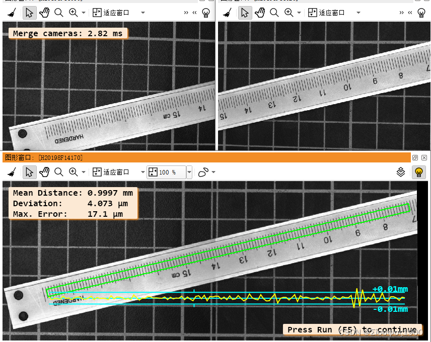
四、疑问
虽然上面的原理我懂了,但是对于这种方法有几个细节东西还有疑惑,望各位帮忙
1、加入两个标定板直接不仅有平移关系,还有旋转关系,只是在两个标定板之间再添加一个旋转关系吗,对于高精度的项目来说,两个标定板的厚度是不是要做一个矫正?
2、在实际的项目中,标定板如何定做,对精度有要求的,不然可以直接打印一张纸上画两个标定板
以上两个问题我已解决,后面我会做一个文章专门回答这个问题


 5146
5146

 被折叠的 条评论
为什么被折叠?
被折叠的 条评论
为什么被折叠?
 到【灌水乐园】发言


