


Arduino-外部中断函数介绍和使用
📖外部中断函数
attachInterrupt():设置中断,根据不同的开发板,中断引脚不同。

- 🌿对于328P单片机处理INT0和IT1外部中断引脚外,还支持端口引脚(电平变化)中断,分别对应中断向量表中的:PCINT0,PCINT1,PCINT2,PCINT3,几乎所有的引脚都支持这种电平变化中断,不过它们都共用这4个中断源。


ESP8266支持除GPIO16外的任何GPIO中的中断。
detachInterrupt():取消指定引脚的中断interrupts():开中断noInterrupts():关中断
📝注意事项
在中断服务函数中,
delay()不起作用,而millis()返回的值也不会递增。在函数中接收的串行数据可能会丢失。在中断服务函数中修改的任何变量都应该声明为volatile。如果想在中断服务函数中使用延时,delayMicroseconds()可以使用这个来延时。
中断函数语法、
attachInterrupt(digitalPinToInterrupt(pin), ISR, mode)
digitalPinToInterrupt(pin):中断引脚
ISR中断发生时调用的ISR;这个函数不能接受任何参数,也不能返回任何内容。这个函数有时被称为中断服务程序。
mode:中断模式(4种)
- CHANGE:当引脚改变值时触发中断-例如从HIGH到LOW或LOW到HIGH;
- FALLING:当触发信号从高电平到低电平是触发;
- RISING:当引脚从低电平到高电平时触发。
- LOW: 当引脚为低电平时触发中断服务程序
- 🔖AVR单片机中断控制:

📑Arduino UNO开启外部2号引脚触发中断 (Arduino UNO中断引脚有2个,2和3)
const byte ledPin = 13;
const byte interruptPin = 2;
volatile byte state = LOW;

void setup() {
  pinMode(ledPin, OUTPUT);
  pinMode(interruptPin, INPUT_PULLUP);
  attachInterrupt(digitalPinToInterrupt(interruptPin), blink, CHANGE);
}

void loop() {
  digitalWrite(ledPin, state);
}

void blink() {
  state = !state;
}
📝detachInterrupt(digitalPinToInterrupt(pin)):取消指定类型的中断.
interrupts()函数原型:#define interrupts() sei()
void setup() {}

void loop()
{
  noInterrupts();
  // critical, time-sensitive code here
  interrupts();
  // other code here
}
noInterrupts()函数原型:#define noInterrupts() cli()
void setup() {}

void loop()
{
  noInterrupts();
  // critical, time-sensitive code here
  interrupts();
  // other code here
}
📘寄存器配置外部中断示例
- 配置外部中断0(PD2)2号引脚作为外部中断引脚
volatile bool ext_int0_flag = 0;
void ext_int0_init(void)
{
// External Interrupt(s) initialization
// INT0: On
// INT0 Mode: Any change
// INT1: Off
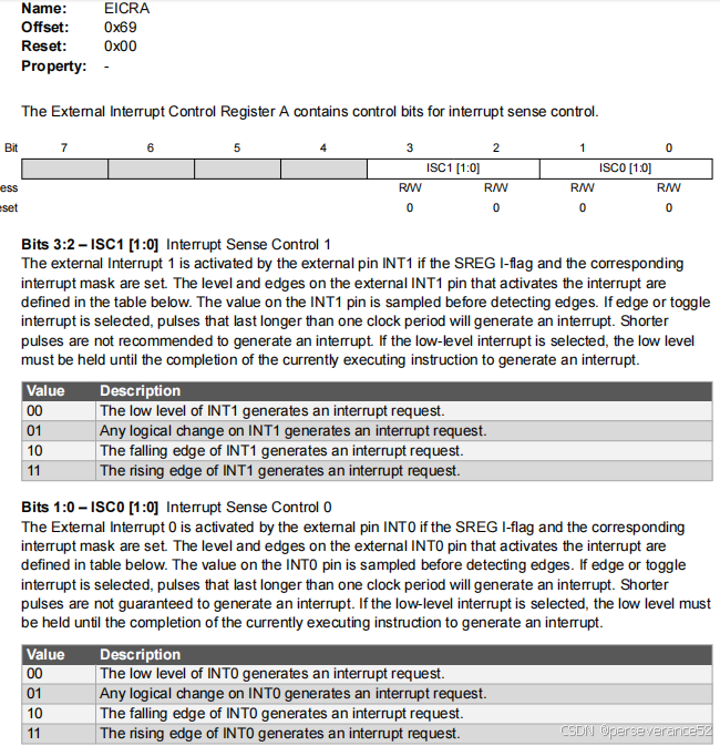
EICRA=(0<<ISC11) | (0<<ISC10) | (0<<ISC01) | (1<<ISC00);//外部中断控制寄存器,信号跳变触发
EIMSK=(0<<INT1) | (1<<INT0);//启用外部中断请求0
EIFR=(0<<INTF1) | (1<<INTF0);//中断标志位清除。
PCICR=(0<<PCIE3) | (0<<PCIE2) | (0<<PCIE1) | (0<<PCIE0);//IO引脚扩展中断不启用
}
// the setup function runs once when you press reset or power the board
void setup() {
// initialize digital pin LED_BUILTIN as an output.
pinMode(LED_BUILTIN, OUTPUT);
Serial.begin(115200);
ext_int0_init();
}
ISR(INT0_vect)
{
ext_int0_flag = 1;
}
// the loop function runs over and over again forever
void loop() {
if (ext_int0_flag)
{
ext_int0_flag = 0;
PORTB ^= (1 << PINB5);//板载led 闪烁一次
Serial.println("ext int0 Trg!\r\n");
}
}
- 如果需要开启外部中断0和1:
volatile bool  ext_int0_flag = 0;
volatile bool  ext_int1_flag = 0;

void ext_int0_init(void)
{

// External Interrupt(s) initialization
// INT0: On
// INT0 Mode: Any change
// INT1: Off
    EICRA=(0<<ISC11) | (1<<ISC10) | (0<<ISC01) | (1<<ISC00);//外部中断控制寄存器,信号跳变触发
    EIMSK=(1<<INT1) | (1<<INT0);//启用外部中断请求1
    EIFR=(1<<INTF1) | (1<<INTF0);//中断标志位清除。
    PCICR=(0<<PCIE3) | (0<<PCIE2) | (0<<PCIE1) | (0<<PCIE0);

}
// the setup function runs once when you press reset or power the board
void setup() {
  // initialize digital pin LED_BUILTIN as an output.
  pinMode(LED_BUILTIN, OUTPUT);
  Serial.begin(115200);
  ext_int0_init();
}
//外部中断0
ISR(INT0_vect)
{

    ext_int0_flag = 1;

}
//外部中断1
ISR(INT1_vect)
{

  ext_int1_flag = 1;
}

// the loop function runs over and over again forever
void loop() {
  // digitalWrite(LED_BUILTIN, HIGH);  // turn the LED on (HIGH is the voltage level)
  // delay(1000);                      // wait for a second
  // digitalWrite(LED_BUILTIN, LOW);   // turn the LED off by making the voltage LOW
  // delay(1000);                      // wait for a second
  // Serial.println("Hello World2");
  if (ext_int0_flag)
        {
            ext_int0_flag = 0;
            PORTB ^= (1 << PINB5);//1秒钟闪烁一次
            Serial.println("ext int0 Trg!\r\n");
        }
          if (ext_int1_flag)
        {
            ext_int1_flag = 0;
            PORTB ^= (1 << PINB5);//1秒钟闪烁一次
            Serial.println("ext int1 Trg!\r\n");
        }
}
🥕对于Atmega328P、ATmega8等AVR带比较器外设的,可以利用比较器扩展外部中断
- 📍资料参考来运:
https://www.geek-workshop.com/thread-11507-1-1.html - 📝测试代码:
/*
328p通过内部比较器扩展外部中断
对应的引脚是arduino 的PIN D6 ,D7 .
AIN0 -> PD6 (正反馈输入引脚)
AIN1 -> PD7 (负反馈输入引脚)
比较器大家都比较熟悉,常用的比较器型号像LM393分正反馈与负反馈,
328P片上集成的也是一样有正负反馈. D6是正反馈,D7是负反馈.
D6正反馈可以通过寄存器操作与能隙基准源连接,D6引脚
中断号:ISR(ANALOG_COMP_vect)  24
*/
#include <ACD.h>

int pin = 13;
volatile int state = LOW;

QUN M; //你要做的只是添加上这个

void setup()
{
  pinMode(pin, OUTPUT);
  M.attachInterrupt(blink, M_CHANGE); //格式是:M.attachInterrupt(blink, M_CHANGE);
                                      //blink是要执行的函数,
                                     // M_CHANGE 当引脚电平发生改变时,触发中断
                                     // M_RISING 当引脚由低电平变为高电平时,触发中断
                                     // M_FALLING 当引脚由高电平变为低电平时,触发中断

  Serial.begin(9600);
}

void loop()
{
  digitalWrite(pin, state);
}


void blink()
{
  state = !state;//当负反馈端(AIN1)PD7引脚电平发生改变时,触发中断
  Serial.println("ANALOG_COMP ISR Trg");

}
- 📗不使用库代码实现:
//------------------------------------------------------------
// The two LEDs are a red one on D13 which simply blinks every
// 'redDelay' milli-seconds and a green one on D8 controlled
// by the Analog Comparator interrupt.
//------------------------------------------------------------
const uint8_t redLED = 13;
#define M_CHANGE 0
#define M_RISING 2
#define M_FALLING 3

void CMP_Init(unsigned char bytes)
{
  PORTD|=_BV(PORTD7);
    DIDR1|=_BV(AIN1D)|_BV(AIN0D);
    ACSR=0;
    ACSR|=_BV(ACIE)|_BV(ACBG)|bytes;
    SREG|=(1<<7);

}
void setup() {
  // put your setup code here, to run once:
 pinMode(redLED, OUTPUT);
  Serial.begin(9600);
  CMP_Init(M_CHANGE);

}

void loop() {
  // put your main code here, to run repeatedly:

}

// The ISR for the Analog Comparator sets the LED on pin 8 to
// the same state as the ACO bit in the ACSR register.
//------------------------------------------------------------
ISR(ANALOG_COMP_vect) {
    digitalWrite(redLED, !!(ACSR & (1 << ACO)));
    Serial.println("ANALOG_COMP ISR Trg");
}
- 🎈其它相关比较器使用库:
https://github.com/NormanDunbar/libAnaComp/tree/main
📙端口引脚电平变化中断
在Atmega328上有两个正常的硬件中断,从中断向量表中可以看到分别是INT0和INT1。这两个中断对应的引脚为PD2和PD3。除了这两个中断外,其余的硬件中断为“Pin-Change Interrupt”,简记为PCINT。PCINT分为三组。每组对应8个Pin,通过寄存器PCICR、PCIFR和PCMSKn(n:0-3),从而实现了所有GPIO都可以用作中断引脚。
📒测试例程:
/*
PCICR – 引脚改变中断控制寄存器,BIT4:0 ->PCIE4:PCIE0分别对应PF PE PD PC PB端口;当对应为写1时,对应端口引脚中断被使能。
PCIFR – 引脚改变中断标志寄存器BIT4:0 -> PCIF4:PCIF1  分别对应PF PE PD PC PB端口引脚改变中断标志位;对应为写1清零
PCMSK0  引脚改变中断屏蔽寄存器0 BIT7:0 对应PCINT7:PCINT0 对应端口:PB0 - PB7
PCMSK1  引脚改变中断屏蔽寄存器1 BIT7:0 对应PCINT14:PCINT8 对应端口:PC0 - PC7
PCMSK2  引脚改变中断屏蔽寄存器2 BIT7:0 对应PCINT23:PCINT16 对应端口:PD0 - PD7
PCMSK3 – 引脚改变中断屏蔽寄存器3 BIT7:0 对应PCINT27:PCINT24  对应端口:PE0 - PE7

引脚端口		中断向量  中断号
PB0-PB7 	PCINT0 3
PC0-PC7 	PCINT1  4
PD0-PD7 	PCINT2  5
PE0 - PE7	 PCINT3    27
ISR (PCINT0_vect) 处理 Pin D8 to D13
ISR (PCINT1_vect) 处理 Pin A0 to A5
ISR (PCINT2_vect) 处理 Pin D0 to D7
ISR (PCINT3_vect) 处理 Pin PE00 to PE7

*/

void setup() {
  // put your setup code here, to run once:
pinMode(LED_BUILTIN, OUTPUT);
  Serial.begin(9600);
  PCICR=1<<PCIE1;//使能PC端口引脚中断
  PCIFR=1<<PCIF1;//清空PC端口中断标志位
  PCMSK1=(1<<PCINT9);//使能端口具体中断引脚为PC1
  sei();//使能中断
}

void loop() {
  // put your main code here, to run repeatedly:

}
ISR(PCINT1_vect){
    //你的中断程序
    Serial.println("PCINT1_vect");
    PORTB ^= (1 << PINB5);//PB5状态翻转
    }
- ⚡如果程序中使用了软串口(SoftwareSerial), 包含了(
#include <SoftwareSerial.h>),程序编译会报错,该源文件中已经被定义了相关ISR函数。


 3051
3051

 被折叠的 条评论
为什么被折叠?
被折叠的 条评论
为什么被折叠?
 到【灌水乐园】发言


