


sensor_msgs/CameraInfo Message
File: sensor_msgs/CameraInfo.msg
Raw Message Definition
# This message defines meta information for a camera. It should be in a
# camera namespace on topic "camera_info" and accompanied by up to five
# image topics named:
#
#   image_raw - raw data from the camera driver, possibly Bayer encoded
#   image            - monochrome, distorted
#   image_color      - color, distorted
#   image_rect       - monochrome, rectified
#   image_rect_color - color, rectified
#
# The image_pipeline contains packages (image_proc, stereo_image_proc)
# for producing the four processed image topics from image_raw and
# camera_info. The meaning of the camera parameters are described in
# detail at http://www.ros.org/wiki/image_pipeline/CameraInfo.
#
# The image_geometry package provides a user-friendly interface to
# common operations using this meta information. If you want to, e.g.,
# project a 3d point into image coordinates, we strongly recommend
# using image_geometry.
#
# If the camera is uncalibrated, the matrices D, K, R, P should be left
# zeroed out. In particular, clients may assume that K[0] == 0.0
# indicates an uncalibrated camera.

#######################################################################
#                     Image acquisition info                          #
#######################################################################

# Time of image acquisition, camera coordinate frame ID
Header header    # Header timestamp should be acquisition time of image
                 # Header frame_id should be optical frame of camera
                 # origin of frame should be optical center of camera
                 # +x should point to the right in the image
                 # +y should point down in the image
                 # +z should point into the plane of the image


#######################################################################
#                      Calibration Parameters                         #
#######################################################################
# These are fixed during camera calibration. Their values will be the #
# same in all messages until the camera is recalibrated. Note that    #
# self-calibrating systems may "recalibrate" frequently.              #
#                                                                     #
# The internal parameters can be used to warp a raw (distorted) image #
# to:                                                                 #
#   1. An undistorted image (requires D and K)                        #
#   2. A rectified image (requires D, K, R)                           #
# The projection matrix P projects 3D points into the rectified image.#
#######################################################################

# The image dimensions with which the camera was calibrated. Normally
# this will be the full camera resolution in pixels.
uint32 height
uint32 width

# The distortion model used. Supported models are listed in
# sensor_msgs/distortion_models.h. For most cameras, "plumb_bob" - a
# simple model of radial and tangential distortion - is sufficient.
string distortion_model

# The distortion parameters, size depending on the distortion model.
# For "plumb_bob", the 5 parameters are: (k1, k2, t1, t2, k3).
float64[] D

# Intrinsic camera matrix for the raw (distorted) images.
#     [fx  0 cx]
# K = [ 0 fy cy]
#     [ 0  0  1]
# Projects 3D points in the camera coordinate frame to 2D pixel
# coordinates using the focal lengths (fx, fy) and principal point
# (cx, cy).
float64[9]  K # 3x3 row-major matrix

# Rectification matrix (stereo cameras only)
# A rotation matrix aligning the camera coordinate system to the ideal
# stereo image plane so that epipolar lines in both stereo images are
# parallel.
float64[9]  R # 3x3 row-major matrix

# Projection/camera matrix
#     [fx'  0  cx' Tx]
# P = [ 0  fy' cy' Ty]
#     [ 0   0   1   0]
# By convention, this matrix specifies the intrinsic (camera) matrix
#  of the processed (rectified) image. That is, the left 3x3 portion
#  is the normal camera intrinsic matrix for the rectified image.
# It projects 3D points in the camera coordinate frame to 2D pixel
#  coordinates using the focal lengths (fx', fy') and principal point
#  (cx', cy') - these may differ from the values in K.
# For monocular cameras, Tx = Ty = 0. Normally, monocular cameras will
#  also have R = the identity and P[1:3,1:3] = K.
# For a stereo pair, the fourth column [Tx Ty 0]' is related to the
#  position of the optical center of the second camera in the first
#  camera's frame. We assume Tz = 0 so both cameras are in the same
#  stereo image plane. The first camera always has Tx = Ty = 0. For
#  the right (second) camera of a horizontal stereo pair, Ty = 0 and
#  Tx = -fx' * B, where B is the baseline between the cameras.
# Given a 3D point [X Y Z]', the projection (x, y) of the point onto
#  the rectified image is given by:
#  [u v w]' = P * [X Y Z 1]'
#         x = u / w
#         y = v / w
#  This holds for both images of a stereo pair.
float64[12] P # 3x4 row-major matrix


#######################################################################
#                      Operational Parameters                         #
#######################################################################
# These define the image region actually captured by the camera       #
# driver. Although they affect the geometry of the output image, they #
# may be changed freely without recalibrating the camera.             #
#######################################################################

# Binning refers here to any camera setting which combines rectangular
#  neighborhoods of pixels into larger "super-pixels." It reduces the
#  resolution of the output image to
#  (width / binning_x) x (height / binning_y).
# The default values binning_x = binning_y = 0 is considered the same
#  as binning_x = binning_y = 1 (no subsampling).
uint32 binning_x
uint32 binning_y

# Region of interest (subwindow of full camera resolution), given in
#  full resolution (unbinned) image coordinates. A particular ROI
#  always denotes the same window of pixels on the camera sensor,
#  regardless of binning settings.
# The default setting of roi (all values 0) is considered the same as
#  full resolution (roi.width = width, roi.height = height).
RegionOfInterest roi

Compact Message Definition
std_msgs/Header header
uint32 height
uint32 width
string distortion_model
float64[] D
float64[9] K
float64[9] R
float64[12] P
uint32 binning_x
uint32 binning_y
sensor_msgs/RegionOfInterest roi
autogenerated on Fri, 15 Jan 2021 03:18:41
header:标准消息头
seq:序列ID,连续递增的ID号
stamp:两个时间戳
frame_id:与此数据相关联的帧ID
height:图像尺寸,height代表高度,(heightwidth)相机的分辨率,以像素为单位
width:图像尺寸,width代表宽度,(heightwidth)相机分辨率,以像素为单位
distortion_model:指定了相机畸变模型,对于大多数相机,"plumb_bob"简单的径向和切向畸变模型就足够了
D:畸变参数,取决于畸变模型,(k1, k2, t1, t2, k3),(我的这个usb相机号称是无畸变相机,但通过标定结果可以看出来还是存在畸变的,是不是被商家坑了,哈哈哈)
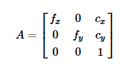
K:相机内参矩阵,使用焦距(fx, fy)和主点坐标(cx, cy),单位为像素,内参矩阵可以将相机坐标中的3D点投影到2D像素坐标
R:旋转矩阵,将相机坐标系统对准理想的立体图像平面,使两张立体图像中的极线平行
P:投影矩阵
左边3*3矩阵是相机的内参矩阵,将相机坐标中的3D点投影到2D像素坐标,可能与相机内参K不同。对于单目相机Tx = Ty = 0。对于双目相机,Tx和Ty有所不同。
binning_x:图像下采样参数,水平方向
binning_y:图像下采样参数,竖直方向
(width / binning_x) x (height / binning_y)
下采样:binning_x = binning_y > 1。缩小图像,生成对应图像的缩略图,使得图像符合显示区域的大小。
roi:感兴趣区域定义,即完整图像上的一个矩形子窗口
其中k
     [fx  0 cx]
 K = [ 0 fy cy]
     [ 0  0  1]
rostopic echo /camera/depth/camera_info
以下是关于sensor_msgs/CameraInfo Message 的🌰
https://vimsky.com/examples/detail/python-method-sensor_msgs.msg.CameraInfo.html
# 需要导入模块: from sensor_msgs import msg [as 别名]
# 或者: from sensor_msgs.msg import CameraInfo [as 别名]
def __init__(self, camera_name, base_frame, table_height):
        """
        Initialize the instance

        :param camera_name: The camera name. One of (head_camera, right_hand_camera)
        :param base_frame: The frame for the robot base
        :param table_height: The table height with respect to base_frame
        """
        self.camera_name = camera_name
        self.base_frame = base_frame
        self.table_height = table_height

        self.image_queue = Queue.Queue()
        self.pinhole_camera_model = PinholeCameraModel()
        self.tf_listener = tf.TransformListener()

        camera_info_topic = "/io/internal_camera/{}/camera_info".format(camera_name)
        camera_info = rospy.wait_for_message(camera_info_topic, CameraInfo)

        self.pinhole_camera_model.fromCameraInfo(camera_info)

        cameras = intera_interface.Cameras()
        cameras.set_callback(camera_name, self.__show_image_callback, rectify_image=True)
内参是一个3×3 的矩阵,
其中cx和cy,它们表示相机光轴在图像坐标系中的偏移量,以像素为单位。但对于焦距fx和fy
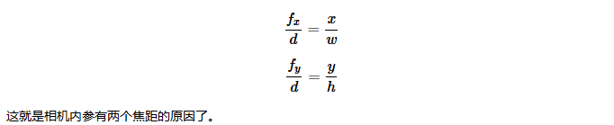
就不是很直观了。为什么一个相机会出现两个焦距呢?在我们习惯使用的相机针孔模型中,一个透镜的焦距通常只有一个。然而我们不能用针孔模型去解释这两个内参中的焦距。但我们可以从透视规律来解释这两个焦距。
由相机拍摄得到的图像是遵从线性透视规律的。也就是说,一个物体的的宽和高会随着这个物体与相机间的距离增加而按比例变小。而对于一张矩形的图片,一个物体的宽和高则会根据物体与相机的距离按不同的比例变小。而这个比例,就是根据相机的焦距得到的。现在我们再利用针孔模型推导出这个比例关系,
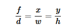
以上是当图像是正方形时的关系,就是当fx=fy时的情况。其中f是相机的焦距,以像素为单位;d为物体到相机的距离,单位为米;x是物体在图像中的宽度,w为物体的实际宽度;y是物体在图像中的高度,而h是物体的实际高度。而对于一张矩形的图像,则有


 4840
4840


 被折叠的 条评论
为什么被折叠?
被折叠的 条评论
为什么被折叠?
 到【灌水乐园】发言


