


最近要应用一个AD,低功耗需求,不能上SOC,寄存器配置又臭又长,简单写一个IIC配置数组。
首先看一下协议:
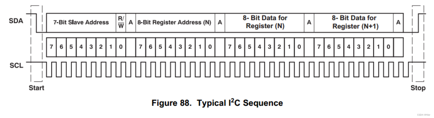
典型IIC,两条线,一根时钟,一根数据。启动时SCL时钟滞后于SDA,结束时提前。
将程序分为两个模块:
1.驱动模块:具体接口协议实现
2.配置模块:定义写多少个寄存器,写什么数据
在驱动模块中:
这部分比较简单,只需要与上层做简单的交互,接收上层的信息,按照协议输入到设备。
端口:
	input 						clk_10MHz,
	input 	      				clk_i,
	input						rst_n,

	input 						wr_rd_flag,	//0 wr -- 1 rd
	input 						start_en,

	input		[ 7:0] 			i2c_device_addr,
	input		[ 7:0] 			register,
	input 		[ 7:0]			data_byte,

	output reg  				scl,
	inout 						sda,
	output reg 					busy,
	output reg 					err
其他的就是做一个inout输入输出切换,按照时序撸就可以了。
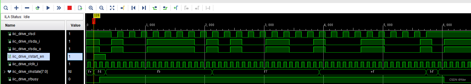
实时抓取的数据写入及应答:
代码(只简单做了写操作,就不详细解释了,很简单:
assign sda = (cstate == start_bit || cstate == idle || cstate == i2c_over)? sda_o :( Rec_count >16'd16 || Rec_count ==16'd0 )? 1'bz : sda_o ;// || nstate != start_bit)? 1'bz : sda_o  ;
//assign sda = ( Rec_count >16'd16 || Rec_count ==16'd0 )? 1'bz : sda_o ;
assign sda_i = sda;
always @(*) begin
    case (cstate)
		idle:			nstate <=	(start_en)		? start_bit 	: idle;
		start_bit:		nstate <=	(State_turn)	? wr_dev_ctrl	: start_bit;
		wr_dev_ctrl:	nstate <=	(State_turn)	? wr_reg		: wr_dev_ctrl;
		wr_reg:			nstate <=	(State_turn)	? wr_data_byte	: wr_reg;
		wr_data_byte:	nstate <=	(State_turn)	? i2c_over		: wr_data_byte;
		i2c_over:		nstate <=	(State_turn)	? idle			: i2c_over;

	endcase
end
// busy
always @(posedge clk_i or negedge rst_n)
begin
	if(!rst_n) begin
		busy	<= 1'b1;
	end
	else begin
		case (nstate)
			idle:	begin
				busy	<= 1'b0;
			end
			wr_dev_ctrl,wr_reg,wr_data_byte,i2c_over,start_bit:begin
				busy	<= 1'b1;
			end
		endcase
	end

end
// scl
always @(posedge clk_i or negedge rst_n)
begin
	if(!rst_n) begin
		scl	<= 1'b1;
	end
	else begin
		case (nstate)
			idle,i2c_over,start_bit:	begin
				scl	<= 1'b1;
			end
			wr_dev_ctrl,wr_reg,wr_data_byte:begin
				scl	<= ~scl;
			end
		endcase
	end

end

//sda_o
always @(posedge clk_i or negedge rst_n)
begin
	if(!rst_n) begin
		sda_o		<= 1'b1;
		dev_r 		<= 8'hff;
		reg_r 		<= 8'hff;
		data_byte_r <= 8'hff;
	end
	else begin
		case (nstate)
			idle:begin
				sda_o	<= 1'b1;
			end
			start_bit: begin
				sda_o		<= 1'b0;
				dev_r 		<= {i2c_device_addr[7:1] , wr_rd_flag};
				reg_r 		<= register;
				data_byte_r <= data_byte;
			end
			i2c_over:	begin
				sda_o		<= 1'b0;
				dev_r 		<= dev_r;
				reg_r 		<= reg_r;
				data_byte_r <= data_byte_r;
			end
			wr_dev_ctrl:begin
				reg_r 		<= reg_r;
				data_byte_r <= data_byte_r;
				if(Rec_count >=16'd16)begin
					sda_o	<= 1'b1;
				end
				else begin
					sda_o	<= dev_r[7];
					if(!scl)begin
						dev_r <= {dev_r[6:0],dev_r[7]};
					end
				end
			end
			wr_reg:begin
				dev_r 		<= dev_r;
				data_byte_r <= data_byte_r;
				if(Rec_count >=16'd16)begin
					sda_o	<= 1'b1;
				end
				else begin
					sda_o	<= reg_r[7];
					if(!scl)begin
						reg_r <= {reg_r[6:0],reg_r[7]};
					end
				end
			end
			wr_data_byte:begin
				dev_r <= dev_r;
				reg_r <= reg_r;
				if(Rec_count >=16'd16)begin
					sda_o	<= 1'b1;
				end
				else begin
					sda_o	<= data_byte_r[7];
					if(!scl)begin
						data_byte_r <= {data_byte_r[6:0],data_byte_r[7]};
					end
				end
			end
		endcase
	end
end
//count
always @(posedge clk_i or negedge rst_n)
begin
	if(!rst_n) begin
		Rec_count	<= 16'd0;
		State_turn  <=  1'b0;
	end
	else begin
		case (nstate)
			idle:begin
				Rec_count	<= 16'd0;
				State_turn 	<=  1'b0;
			end
			start_bit,i2c_over:begin
				if (Rec_count == 16'd2 - 1'b1) begin
					Rec_count  	<= 16'd0;
					State_turn  <=  1'b1;
				end
				else 							begin
					Rec_count  	<= Rec_count + 1'b1;
					State_turn  <= 1'b0;
				end
			end
			wr_dev_ctrl:begin
				if (Rec_count == 16'd18 - 1'b1) begin
					Rec_count  	<= 16'd0;
					State_turn  <=  1'b1;
				end
				else 							begin
					Rec_count  	<= Rec_count + 1'b1;
					State_turn  <= 1'b0;
				end
			end
			wr_reg:begin
				if (Rec_count == 16'd18 - 1'b1) begin
					Rec_count  	<= 16'd0;
					State_turn  <=  1'b1;
				end
				else 							begin
					Rec_count  	<= Rec_count + 1'b1;
					State_turn  <= 1'b0;
				end
			end
			wr_data_byte:begin
				if (Rec_count == 16'd18 - 1'b1) begin
					Rec_count  	<= 16'd0;
					State_turn  <=  1'b1;
				end
				else 							begin
					Rec_count  	<= Rec_count + 1'b1;
					State_turn  <= 1'b0;
				end
			end
		endcase
	end
end
//err
always @(posedge clk_i or negedge rst_n)
begin
	if(!rst_n) begin
		err	<= 1'b0;
	end
	else begin
		case (nstate)
			idle,i2c_over,start_bit:	begin
				err	<= err;
			end
			wr_dev_ctrl,wr_reg,wr_data_byte:begin
				if(Rec_count >=16'd15) begin
					if(sda_i) 	err	<= 1'b0;
					else 		err	<= 1'b1;
				end
				else begin
					err	<= err;
				end
			end
		endcase
	end

end

always @(posedge clk_i or negedge rst_n) begin
    if(!rst_n)
        cstate <= idle;
    else begin
        cstate <= nstate;
    end
end
在配置模块中:
共需要写入3种数据,设备地址,寄存器地址,寄存器数据。
因为需要做数组数据输入,因设备地址在对单个设备配置时是固定的,则可以定义为常量REG类型,当挂载多个设备时只需更新这个变量。
其他数据定义为数组。
具体代码如下:
I2C_DEVICE_ADDR:定义设备地址
IIC_REG_COUNT :定义需要写入数据个数,对应IIC_REG_DATA 数组
IIC_REG_DATA :奇数字节为寄存器地址,偶数为寄存器数据
更换设备或更改寄存器时只需要改上面几个
module iic_reg_init#(
	parameter					IIC_REG_COUNT = 16'd9,
	parameter					I2C_DEVICE_ADDR = 8'b1001_1110,
	parameter					I2C_length = IIC_REG_COUNT*16 - 4'd1
	//parameter						;

)(
	input 						clk_10MHz,
	input 	      				clk_i,
	input						rst_n,

	output reg 					wr_rd_flag,	//0 wr -- 1 rd
	output reg 					start_en,

	output   	[ 7:0] 			i2c_device_addr,
	output reg	[ 7:0] 			register,
	output reg  [ 7:0]			data_byte,


	input	 					busy,
	input	 					err,
	input 						tri_en

    );
									//register // data_byte
reg [I2C_length :0]	IIC_REG_DATA = { 	8'h00, 	8'h00,
										//8'h01,	8'h01,
										8'h07,	8'h30,
										8'h08,	8'h02,
										8'h0B,	8'h00,
										8'h0C,	8'h01,
										8'h0D,	8'h02,
										8'h0E,	8'h03,
										8'h13,	8'h06,
										8'h1F,	8'h43
						};
写入流程要和驱动进行交互,代码如下:
ssign i2c_device_addr = I2C_DEVICE_ADDR;
always @(*) begin
    case (cstate)
		ele_delay:		nstate <=	(State_turn)				? idle 			: ele_delay;
		idle:			nstate <=	(!busy && iic_count != 0)	? reg_sent		: idle;
		reg_sent:		nstate <=	delay;
		delay:			nstate <=	delay_cnt;
		delay_cnt:		nstate <=	(State_turn)				? idle			: delay_cnt;
	endcase
end
//	iic_count
always @(posedge clk_i or negedge rst_n)
begin
	if(!rst_n) begin
		iic_count <= IIC_REG_COUNT - 1'b1;
		start_en		<= 1'b0;
		wr_rd_flag		<= 1'b0;
	end
	else begin
		if(tri_en) begin
			iic_count <= IIC_REG_COUNT - 1'b1;
			start_en		<= 1'b0;
			wr_rd_flag		<= 1'b0;
		end
		else begin
			case (nstate)
				reg_sent:	begin
					iic_count <= iic_count - 1'b1;
					start_en		<= 1'b1;
					wr_rd_flag		<= 1'b0;
				end
				delay: begin
					iic_count <= iic_count;
					start_en		<= 1'b1;
					wr_rd_flag		<= 1'b0;
				end
				ele_delay,idle,delay,delay_cnt:begin
					iic_count <= iic_count;
					start_en		<= 1'b0;
					wr_rd_flag		<= 1'b0;
				end
			endcase
		end
	end

end
always @(posedge clk_i or negedge rst_n)
begin
	if(!rst_n) begin
		IIC_REG_DATA_r <= IIC_REG_DATA;
	end
	else begin
		case (nstate)
			reg_sent:	begin
				register 	<= IIC_REG_DATA_r[I2C_length 		:I2C_length - 4'd7];
				data_byte 	<= IIC_REG_DATA_r[I2C_length - 4'd8 :I2C_length - 4'd15];
				IIC_REG_DATA_r<= { IIC_REG_DATA_r[I2C_length - 8'd16:4'd15],IIC_REG_DATA_r[I2C_length - 4'd15:0]};
			end
			ele_delay,idle,delay,delay_cnt:begin
				IIC_REG_DATA_r <= IIC_REG_DATA_r;
			end
		endcase
	end
end
always @(posedge clk_i or negedge rst_n)
begin
	if(!rst_n) begin
		Rec_count	<= 32'd1000;
		State_turn  <=  1'b0;
	end
	else begin
		case (nstate)
			ele_delay:begin
				if (Rec_count == 32'd1000 - 1'b1) begin
					Rec_count  	<= 32'd0;
					State_turn  <=  1'b1;
				end
				else 							begin
					Rec_count  	<= Rec_count + 1'b1;
					State_turn  <= 1'b0;
				end
			end
			delay_cnt:begin
				if (Rec_count == 32'd1000 - 1'b1) begin
					Rec_count  	<= 32'd0;
					State_turn  <=  1'b1;
				end
				else 							begin
					Rec_count  	<= Rec_count + 1'b1;
					State_turn  <= 1'b0;
				end
			end
			idle,delay,reg_sent:begin
				Rec_count	<= 16'd0;
				State_turn 	<=  1'b0;
			end
		endcase
	end
end
always @(posedge clk_i or negedge rst_n) begin
    if(!rst_n)
        cstate <= idle;
    else begin
        cstate <= nstate;
    end
end
busy信号和err信号都为测试信号,按需求应用即可。
clk_i时钟为iic scl时钟×2


 1万+
1万+


 被折叠的 条评论
为什么被折叠?
被折叠的 条评论
为什么被折叠?
 到【灌水乐园】发言


