


主要学习内容为里程计精度评价和点云畸变矫正,学习文章为:文章一、文章二。
关于里程计精度评价
内容比较简单,增加了两部分的内容:
第一个是针对文件操作写了一个独立的class,将创建文件和创建文件路径写成了两个成员函数,方便之后的调用。
第二个就是精度评价,EVO,详细内容这篇文章讲的很好。
一、关于文件操作
直接将类写在了tools文件夹中:file_manager.hpp、file_manager.cpp。
file_manager.hpp:
#ifndef LIDAR_LOCALIZATION_TOOLS_FILE_MANAGER_HPP_
#define LIDAR_LOCALIZATION_TOOLS_FILE_MANAGER_HPP_

#include <string>
#include <iostream>
#include <fstream>

namespace lidar_localization {
class FileManager{
  public:
    static bool CreateFile(std::ofstream& ofs, std::string file_path);
    static bool CreateDirectory(std::string directory_path);
};
}

#endif
主要是关于FileManager类的定义,两个bool类型的函数CreateFile()和CreateDirectory()。
file_manager.cpp:
#include "lidar_localization/tools/file_manager.hpp"

#include <boost/filesystem.hpp>
#include "glog/logging.h"

namespace lidar_localization {
bool FileManager::CreateFile(std::ofstream& ofs, std::string file_path) {
    ofs.open(file_path.c_str(), std::ios::app);
    if (!ofs) {
        LOG(WARNING) << "无法生成文件: " << file_path;
        return false;
    }

    return true;
}

bool FileManager::CreateDirectory(std::string directory_path) {
    if (!boost::filesystem::is_directory(directory_path)) {
        boost::filesystem::create_directory(directory_path);
    }
    if (!boost::filesystem::is_directory(directory_path)) {
        LOG(WARNING) << "无法建立文件夹: " << directory_path;
        return false;
    }
    return true;
}
}CreateFile函数主要使用了文件流的操作,std::ios::app,app(append),具体看文章。
而CreateDirectory函数利用了filesystem里面的两个函数is_directory和create_directory来判断是否有这个路径,如果没有这个路径就创建这个路径。
准备一个练习,熟悉一下这个几个函数。最少有好几个迭代文件。
然后就是front_end_flow.cpp里面的应用部分:
bool FrontEndFlow::SaveTrajectory() {
    static std::ofstream ground_truth, laser_odom;
    static bool is_file_created = false;
    if (!is_file_created) {
        if (!FileManager::CreateDirectory(WORK_SPACE_PATH + "/slam_data/trajectory"))
            return false;
        if (!FileManager::CreateFile(ground_truth, WORK_SPACE_PATH + "/slam_data/trajectory/ground_truth.txt"))
            return false;
        if (!FileManager::CreateFile(laser_odom, WORK_SPACE_PATH + "/slam_data/trajectory/laser_odom.txt"))
            return false;
        is_file_created = true;
    }

    for (int i = 0; i < 3; ++i) {
        for (int j = 0; j < 4; ++j) {
            ground_truth << gnss_odometry_(i, j);
            laser_odom << laser_odometry_(i, j);
            if (i == 2 && j == 3) {
                ground_truth << std::endl;
                laser_odom << std::endl;
            } else {
                ground_truth << " ";
                laser_odom << " ";
            }
        }
    }

    return true;
}这个函数有两个部分,第一个就是文件创建部分,第二个是将gnss_odometry和laser_odometry两个里程计的部分存到第一部分创建的文件中去。这两个for循环主要是将4×4的矩阵提取前3行部分,并且每提取完一个就会换行。所以它就是将3 × 4 写入文件的时候写的是1 × 12。然后就生成了两个文件,ground_truth.txt和laser_odom.txt两个文件。为之后的evo评价提供文件。
二、evo评价
主要使用两个命令evo_rpe和evo_ape。
evo_rpe kitti ground_truth.txt laser_odom.txt -r trans_part --delta 100 --plot --plot_mode xyz可通过 evo_rpe +数据格式 + --help查看更多参数的含义以及如何使用。例如
evo_rpe kitti --help比较详细。
evo_ape kitti ground_truth.txt laser_odom.txt -r full --plot --plot_mode xyz同样可以使用help命令查看详细命令。
关于点云畸变矫正
这部分刚开始看的时候有点难以理解,笔记得详细的记录一下。
三、旋转式激光lidar的视场角
关于旋转式激光lidar的基本参数有探测距离、视场(FoV)、扫描模式、抗串扰抗干扰度、检出率、多次回波、测距精度和准确度。详细参考文章。
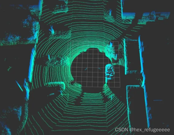
本文只关注,视场角度。kitti数据集采用的是velodyne64线的激光lidar,它在纵向上排列有64个lidar接受器和发射器。这些发射器按水平角(-24.8度到2度),每个相差0.4度。相当于26.8/0.4 = 67个。然后lidar的频率是10hz,就是说每100ms旋转一周。在旋转的过程中不断的发射和接收就会获得n列激光点。n为4500,然后就可以算出它的水平方向上的分辨率是360度/4500 = 0.08度。因为水平方向上的分辨率比竖直方向上的分辨率低很多,所以看到的激光lidar展示的图像上都是一圈一圈的。
四、激光lidar畸变产生原因
而关于激光lidar的矫正的原因,在大佬的文章中写的十分详细,具体的看文章就好了,还找到了一篇文章写的也很好。
五、激光lidar畸变矫正
主要原理是激光点主要是以激光lidar为坐标系原点的,所以计算求得激光lidar相对与最初时刻的位姿变换就可以了,然后将不同时刻获得的激光点的坐标乘以这个转换关系就可以获得最初时刻下的坐标。
1)获取lidar运动的信息,主要是通过订阅获得的速度信息来计算相对位移。
2)获取激光点相对于起始时刻的时间差。
3)根据前面获得的转换矩阵,将激光点坐标转换到要求的坐标系下。
具体的流程公式推导可以看这篇文章,写的很详细。速度在连杆中的传递问题。
六、代码实现
矫正畸变的代码放在了models文件夹下面的scan_adjust文件下,开始分析。
scan_adjust.hpp:
#ifndef LIDAR_LOCALIZATION_MODELS_SCAN_ADJUST_DISTORTION_ADJUST_HPP_
#define LIDAR_LOCALIZATION_MODELS_SCAN_ADJUST_DISTORTION_ADJUST_HPP_

#include <pcl/common/transforms.h>
#include <Eigen/Dense>
#include "glog/logging.h"

#include "lidar_localization/models/scan_adjust/distortion_adjust.hpp"
#include "lidar_localization/sensor_data/velocity_data.hpp"
#include "lidar_localization/sensor_data/cloud_data.hpp"

namespace lidar_localization {
class DistortionAdjust {
  public:
    void SetMotionInfo(float scan_period, VelocityData velocity_data);
    bool AdjustCloud(CloudData::CLOUD_PTR& input_cloud_ptr, CloudData::CLOUD_PTR& output_cloud_ptr);

  private:
    inline Eigen::Matrix3f UpdateMatrix(float real_time);

  private:
    float scan_period_;
    Eigen::Vector3f velocity_;
    Eigen::Vector3f angular_rate_;
};
} // namespace lidar_slam
#endif主要是写了一个DistortionAdjust类,定义了三个私有变量,scan_period_是一帧lidar的时间0.1s,velocity_是线速度向量,angular_rate_是角速度向量。然后有三个函数,SetMotionInfo函数是将相关信息传递赋值给三个变量;AdjustCloud函数是畸变矫正的主要功能实现函数,后面重点分析;UpdateMatrix函数是计算位姿变换的函数就是前面提到的连杆上的速度传递功能的实现。
scan_adjust.cpp:
#include "lidar_localization/models/scan_adjust/distortion_adjust.hpp"
#include "glog/logging.h"

namespace lidar_localization {
void DistortionAdjust::SetMotionInfo(float scan_period, VelocityData velocity_data) {
    scan_period_ = scan_period;
    velocity_ << velocity_data.linear_velocity.x, velocity_data.linear_velocity.y, velocity_data.linear_velocity.z;
    angular_rate_ << velocity_data.angular_velocity.x, velocity_data.angular_velocity.y, velocity_data.angular_velocity.z;
}

bool DistortionAdjust::AdjustCloud(CloudData::CLOUD_PTR& input_cloud_ptr, CloudData::CLOUD_PTR& output_cloud_ptr) {
    CloudData::CLOUD_PTR origin_cloud_ptr(new CloudData::CLOUD(*input_cloud_ptr));
    output_cloud_ptr->points.clear();

    float orientation_space = 2.0 * M_PI;
    // 这里的是 5.0 * (2 * M_PI / 360.0)  弧度
    float delete_space = 5.0 * M_PI / 180.0;
    float start_orientation = atan2(origin_cloud_ptr->points[0].y, origin_cloud_ptr->points[0].x);

    Eigen::AngleAxisf t_V(start_orientation, Eigen::Vector3f::UnitZ());
    Eigen::Matrix3f rotate_matrix = t_V.matrix();
    Eigen::Matrix4f transform_matrix = Eigen::Matrix4f::Identity();
    transform_matrix.block<3,3>(0,0) = rotate_matrix.inverse();
    // 转换到0度坐标系
    pcl::transformPointCloud(*origin_cloud_ptr, *origin_cloud_ptr, transform_matrix);

    //将线速度和角速度转换到0度的坐标系里面
    velocity_ = rotate_matrix * velocity_;
    angular_rate_ = rotate_matrix * angular_rate_;

    for (size_t point_index = 1; point_index < origin_cloud_ptr->points.size(); ++point_index) {
        // atan2 返回值为弧度制下的角度
        float orientation = atan2(origin_cloud_ptr->points[point_index].y, origin_cloud_ptr->points[point_index].x);
        // 这一步是什么意思?
        if (orientation < 0.0)
            orientation += 2.0 * M_PI;

        // delete_space好像是一个范围
        if (orientation < delete_space || 2.0 * M_PI - orientation < delete_space)
            continue;
        // scan_period_是每一帧lidar的时间,0.1s,
        // 所以这里的real_time就是从第一个点到每一个lidar点所使用的时间,不知道为什么要除以2.0
        float real_time = fabs(orientation) / orientation_space * scan_period_ - scan_period_ / 2.0;

        Eigen::Vector3f origin_point(origin_cloud_ptr->points[point_index].x,
                                     origin_cloud_ptr->points[point_index].y,
                                     origin_cloud_ptr->points[point_index].z);

        Eigen::Matrix3f current_matrix = UpdateMatrix(real_time);
        Eigen::Vector3f rotated_point = current_matrix * origin_point;
        Eigen::Vector3f adjusted_point = rotated_point + velocity_ * real_time;
        CloudData::POINT point;
        point.x = adjusted_point(0);
        point.y = adjusted_point(1);
        point.z = adjusted_point(2);
        output_cloud_ptr->points.push_back(point);
    }

    // 转换回原始坐标系
    pcl::transformPointCloud(*output_cloud_ptr, *output_cloud_ptr, transform_matrix.inverse());
    return true;
}

Eigen::Matrix3f DistortionAdjust::UpdateMatrix(float real_time) {
    Eigen::Vector3f angle = angular_rate_ * real_time;
    Eigen::AngleAxisf t_Vz(angle(2), Eigen::Vector3f::UnitZ());
    Eigen::AngleAxisf t_Vy(angle(1), Eigen::Vector3f::UnitY());
    Eigen::AngleAxisf t_Vx(angle(0), Eigen::Vector3f::UnitX());
    Eigen::AngleAxisf t_V;
    t_V = t_Vz * t_Vy * t_Vx;
    return t_V.matrix();
}
} // namespace lidar_localization
这里就是定义部分了,主要分析AdjustCloud函数和UpdateMatrix函数。
    float orientation_space = 2.0 * M_PI;
    // 这里的是 5.0 * (2 * M_PI / 360.0)  弧度
    float delete_space = 5.0 * M_PI / 180.0;
    float start_orientation = atan2(origin_cloud_ptr->points[0].y, origin_cloud_ptr->points[0].x);
orientation_space是整个lidar一帧点云的整个角度范围,360度。
这里的delete_space应该是指设置的激光lidar的安装部分?可以人为调整。
重点是这里的start_orientation,它是算的lidar第一个点云数据的角度数值,之后的位姿变换全部都是以这个为基准。
    Eigen::AngleAxisf t_V(start_orientation, Eigen::Vector3f::UnitZ());
    Eigen::Matrix3f rotate_matrix = t_V.matrix();
    Eigen::Matrix4f transform_matrix = Eigen::Matrix4f::Identity();
    transform_matrix.block<3,3>(0,0) = rotate_matrix.inverse();
    // 转换到0度坐标系
pcl::transformPointCloud(*origin_cloud_ptr, *origin_cloud_ptr, transform_matrix);这部分就是计算确定位姿的变换矩阵transform_matrix。t_V是计算的旋转轴,根据前面计算出来的第一个点的坐标的角度,算出旋转轴t_V。然后将它转换成3*3的旋转矩阵rotate_matrix,然后初始化transform_matrix矩阵,将旋转部分赋值rotate_matrix。然后使用pcl的函数,将这一帧点云根据这个transform_matrix变换成对应的状态(后面会变换回来)。
    //将线速度和角速度转换到0度的坐标系里面
    velocity_ = rotate_matrix * velocity_;
    angular_rate_ = rotate_matrix * angular_rate_;
线速度和角速度是矢量,所有也将它们变换成相应的旋转位姿。
接下来的for循环是重点。
float orientation = atan2(origin_cloud_ptr->points[point_index].y, origin_cloud_ptr->points[point_index].x);
// 这一步是什么意思?
if (orientation < 0.0)
   orientation += 2.0 * M_PI;
确定接下来的点的角度,如果小于0的话就加上360度,让它为正,不知道为什么要为正。
        if (orientation < delete_space || 2.0 * M_PI - orientation < delete_space)
            continue;
        // scan_period_是每一帧lidar的时间,0.1s,
        // 所以这里的real_time就是从第一个点到每一个lidar点所使用的时间,不知道为什么要除以2.0
        float real_time = fabs(orientation) / orientation_space * scan_period_ - scan_period_ / 2.0;
这里就是如果在delete区域内就放弃矫正这个点,然后后面的real_time就是计算第一个点到当前点花的时间。但最后-scan_period_/2不太理解,评论区说是因为kitti的数据集里面每一帧lidar都是去的中间时刻,所以减去这个就是最初时刻。大概是这样理解,但评论区又说了基准时刻是中间时刻,感觉有点矛盾,姑且认为基准时刻是最初时刻。
Eigen::Vector3f origin_point(origin_cloud_ptr->points[point_index].x,
                             origin_cloud_ptr->points[point_index].y,
                             origin_cloud_ptr->points[point_index].z);

Eigen::Matrix3f current_matrix = UpdateMatrix(real_time);
Eigen::Vector3f rotated_point = current_matrix * origin_point;
Eigen::Vector3f adjusted_point = rotated_point + velocity_ * real_time;
CloudData::POINT point;
point.x = adjusted_point(0);
point.y = adjusted_point(1);
point.z = adjusted_point(2);
output_cloud_ptr->points.push_back(point);
这里重要的是函数UpdateMatrix,它是计算角速度的并转换成3×3矩阵的函数。
Eigen::Matrix3f DistortionAdjust::UpdateMatrix(float real_time) {
    Eigen::Vector3f angle = angular_rate_ * real_time;
    Eigen::AngleAxisf t_Vz(angle(2), Eigen::Vector3f::UnitZ());
    Eigen::AngleAxisf t_Vy(angle(1), Eigen::Vector3f::UnitY());
    Eigen::AngleAxisf t_Vx(angle(0), Eigen::Vector3f::UnitX());
    Eigen::AngleAxisf t_V;
    t_V = t_Vz * t_Vy * t_Vx;
    return t_V.matrix();
}
angle是速度的向量,时间乘以角速度速率等于他,然后根据每一维度转换成欧拉角旋转轴,最后再乘在一起,得到一个完整的欧拉角,然后返回3×3的矩阵形式。返回的值是这个角度,相对于最初角度的旋转矩阵。就是这个lidar点相对于最开始的lidar点的旋转矩阵。
然后就是将更新后的点放在点云指针里面。
pcl::transformPointCloud(*output_cloud_ptr, *output_cloud_ptr, transform_matrix.inverse());这个就是最前面提到的将坐标转换回来。
然后就是velocity_data.cpp里面的TransformCoordinate函数,它的作用是实现连杆速度传递的功能。
void VelocityData::TransformCoordinate(Eigen::Matrix4f transform_matrix) {
    Eigen::Matrix4d matrix = transform_matrix.cast<double>();
    Eigen::Matrix3d t_R = matrix.block<3,3>(0,0);
    Eigen::Vector3d w(angular_velocity.x, angular_velocity.y, angular_velocity.z);
    Eigen::Vector3d v(linear_velocity.x, linear_velocity.y, linear_velocity.z);
    w = t_R * w;
    v = t_R * v;

    Eigen::Vector3d r(matrix(0,3), matrix(1,3), matrix(2,3));
    Eigen::Vector3d delta_v;
    // 好像是线速度和角速度之间的关系
    // 这里使用的是三维向量叉乘的法则
    delta_v(0) = w(1) * r(2) - w(2) * r(1);
    delta_v(1) = w(2) * r(0) - w(0) * r(2);
    delta_v(2) = w(0) * r(1) - w(1) * r(0);
    v = v + delta_v;

    angular_velocity.x = w(0);
    angular_velocity.y = w(1);
    angular_velocity.z = w(2);
    linear_velocity.x = v(0);
    linear_velocity.y = v(1);
    linear_velocity.z = v(2);
}这里主要使用了向量间的叉乘法则,详细内容看:文章一、文章二。
首先是取出t矩阵的旋转部分,然后左乘线速度向量、角速度向量。然后就是线速度等于角速度乘上距离,求得线速度增量,最后在线速度加上增量,然后重新赋值。这里可以练习关于坐标轴转换左乘和右乘、关于旋转轴变换欧拉角之间的练习。
然后就是将三个函数在UpdateLaserOdometry函数里面使用,就是针对点云做的矫正。但还是有很多数学推理方面的公式需要自己推一下。特别是连杆之间的速度传递问题,两个不同的坐标系之间的转换问题,特别是左乘右乘问题,还有一个关于旋转式激光lidar的问题,就是一个lidar有64个接收器,那么它一个周期内接收到的数据是按什么顺序排列的?是依次排列还是说第一个接收器接收完毕后全部写下数据在记录下一个接收器记录的数据。
七、总结点云畸变矫正流程
最开始有一个确定连杆见速度传递的函数,这个主要是针对lidar和imu-gnss之间的刚性坐标的4×4矩阵求得,通过imu-gnss获得的线速度和角速度(后面会用到),转换到lidar上。这里有很多的转换关系,需要仔细的学习推理一下。
1)首先确定矫正方式,主要是载体运动时,lidar采集到的数据一帧之间会有偏移,偏移原因在上文。这时候取得车辆在这一帧之间的运动速度(线速度和角速度),可以采用叠加的方式,将点云畸变校正起来。
2)获取点云第一帧中第一个采集到的点作为基准点,求得它的位姿矩阵,然后将这一帧点云全部转换到这个位姿下,但并不是以这个点为原点,只是以这个点的坐标系的原点为点云的原点。将线速度和角速度向量也转换到这个位姿下,并没有开始正式矫正。
3)然后从这帧点云的采集到的第二个点开始,直到最后一个点。每个点求出自己的位姿角度,注意这个时候算出来的位姿角度已经是在第一个点的坐标系下了。然后获取该点和第一个点的时间差距。
4)根据求得的时间差距,计算出每个点3×3的旋转矩阵。之后将旋转矩阵乘上点云,得到了经过旋转后的点的数据,然后加上线速度×时间等于距离的点就是最后的矫正得到的点。
5)将得到矫正后的点放在输出的点云指针里面。最后在利用第二步的位姿矩阵的逆,将这一帧的点云全部转换回之间的坐标系下,完成矫正。
还是得多找点资料学习一下,感觉理解的并不完全正确。如果有错误,请及时指出,多谢。


 1818
1818


 被折叠的 条评论
为什么被折叠?
被折叠的 条评论
为什么被折叠?
 到【灌水乐园】发言


