


基于FPGA数码管动态驱动实验
硬件介绍
- 国产GW-FPGA 9K开发板
- 四位共阳数码管,其图看博主驱动单个数码管实验—驱动单个数码管实验
功能介绍:
实现简单的数字时钟显示,采用动态扫描的方式驱动四个数码管共同显示
顶层文件源码:
`timescale 1ns / 1ps
//引脚说明:    数码管Out_IO:a~g 38 37 36 29 25 26 27   位选:num: 42 35 41 42   冒号显示 :28
module Fore_LED(
        clk,            //时钟信号
        res_n,          //复位信号
        out_iO,   //数码管输出
        colon,
        num       //数码管位数选择
    );

    input clk;         //时钟信号
    input res_n;       //复位信号
    output reg [6:0] out_iO;   //数码管输出
    output reg colon; // h 数码管小数点显示
    output reg [3:0] num;       //数码管位数选择

    // 1khz的毫秒计数器     计数个数为:27027
    parameter _1KHZ = 27027;
    parameter _1STIM = 1000;
    reg [14:0] _count;
    reg [3:0] count_1khz;
    reg [15:0] count_1s;

    reg [4:0] Display_NUM_H;
    reg [5:0] Display_NUM_Min;
    reg [5:0] Display_NUM_S;

    //最底层1khz计数模块
    always @(posedge clk or negedge res_n) begin
        if(!res_n)
            _count <= 0;
        else if(_count == _1KHZ-1)
            _count <= 0;
        else
            _count <= _count + 1'd1;
    end
    //1ms扫描模块
    always @(posedge clk or negedge res_n) begin
        if(!res_n)
            count_1khz <= 0;
        else if(_count == _1KHZ-2 && count_1khz >= 3'd4 )
            count_1khz <= 0;
        else if(_count == _1KHZ-2)
            count_1khz <= count_1khz + 1'd1;
    end
    //1s定时模块        计数个数 : 27,027,027
    always @(posedge clk or negedge res_n) begin
        if(!res_n)
            count_1s <= 0;
        else if(_count == _1KHZ-2 && count_1s == _1STIM-1)
            count_1s <= 0;
        else if(_count == _1KHZ-2)
            count_1s <= count_1s+1'd1;
    end
    //计数增长模块
    reg _1s_Flag;
	reg _1min_Flag;
    reg Flag_Buf;
    always @(posedge clk or negedge res_n) begin
        if(!res_n) begin
            _1s_Flag <= 0;
            Flag_Buf <= 1;
        end
        else if(count_1s == _1STIM-2) begin
            _1s_Flag <= 0;
            Flag_Buf <= 1;
        end
        else if(count_1s == _1STIM-3 && Flag_Buf == 1) begin
            _1s_Flag<=1;
            Flag_Buf <=0;
        end
        else if(Flag_Buf == 0)
            _1s_Flag<=0;

    end
    //秒加器
    always @(posedge clk or negedge res_n) begin
        if(!res_n) begin
            Display_NUM_S <= 20;
            colon <= 1;
        end
        else if(Display_NUM_S > 60 ) begin
            Display_NUM_S <= 0;
        end
        else if(_1s_Flag == 1)begin
            Display_NUM_S <= Display_NUM_S + 1'd1;
            colon <= ~colon;
        end
    end
    //分加器
    always @(posedge clk or negedge res_n) begin
        if(!res_n)begin
            Display_NUM_Min <= 21;
			_1min_Flag<=0;
		end
        else if(Display_NUM_S >= 60 && Display_NUM_Min >= 60) begin
            Display_NUM_Min <= 0;
        end
        else if(Display_NUM_S >= 60 && _1s_Flag == 1 )begin
            Display_NUM_Min <= Display_NUM_Min + 1'd1;
			_1min_Flag<=1;
		end
		else
			_1min_Flag<=0;
    end

    //时加器
    always @(posedge clk or negedge res_n) begin
        if(!res_n)
            Display_NUM_H <= 13;
        else if(Display_NUM_Min >= 59 && Display_NUM_H >= 24) begin
            Display_NUM_H <= 0;
        end
        else if(Display_NUM_Min >= 59 && _1min_Flag == 1 )
            Display_NUM_H <= Display_NUM_H + 1'd1;
    end

    //共阳数码管  {0xc0,0xf9,0xa4,0xb0,0x99,0x92,0x82,0xf8,0x80,0x90,0x88,0x83,0xc6,0xa1,0x86,0x8e};
    reg [6:0] Digitron_Data [15:0];
    //要显示的数据
    reg [31:0] disp_data;

    always @(posedge clk or negedge res_n) begin
        if(!res_n) begin
            disp_data <= 1;
            Digitron_Data[0] <= 7'hc0;  // 正常顺序
            Digitron_Data[1] <= 7'hf9;
            Digitron_Data[2] <= 7'hA4;
            Digitron_Data[3] <= 7'hb0;
            Digitron_Data[4] <= 7'h99;
            Digitron_Data[5] <= 7'h92;
            Digitron_Data[6] <= 7'h82;
            Digitron_Data[7] <= 7'hF8;
            Digitron_Data[8] <= 7'h80;
            Digitron_Data[9] <= 7'h90;
        end
        else begin

            disp_data[6:0]  <= Digitron_Data[Display_NUM_H/10];
            disp_data[14:8] <= Digitron_Data[Display_NUM_H%10];
            disp_data[22:16]<= Digitron_Data[Display_NUM_Min/10];
            disp_data[30:24]<= Digitron_Data[Display_NUM_Min%10];

        end
    end


    always @(posedge clk or negedge res_n) begin
        if(!res_n)
            num <= 0;
        else begin
            case (count_1khz)
                4'd0: begin
                    num<= 4'b0001;
                    out_iO<= disp_data[6:0];
                end
                4'd1: begin
                    num<= 4'b0010;
                    out_iO<= disp_data[14:8];
                end
                4'd2: begin
                    num<= 4'b0100;
                    out_iO<= disp_data[22:16];
                end
                4'd3: begin
                    num<= 4'b1000;
                    out_iO<= disp_data[30:24];
                end
                default:
                    num <= num;
            endcase
        end
    end

endmodule
testbench文件
`timescale 1ns / 1ns
module Fore_LED_tb();

    reg clk;            //时钟信号
    reg res_n;       //复位信号
    wire [7:0] out_iO;   //数码管输出
    wire [3:0] num;       //数码管位数选择

    Fore_LED #(
        ._1KHZ(102),
        ._1STIM(12)
    ) Fore_LED(
                .clk(clk),          //时钟信号
                .res_n(res_n),      //复位信号
                .out_iO(out_iO),    //数码管输出
                .num(num)           //数码管位数选择
            );

    always #10 clk = ~clk;

    initial begin
        clk = 0;
        // out_iO = 1;
        // num=0;
        res_n = 0;
        #20
        res_n = 1;
    end
endmodule
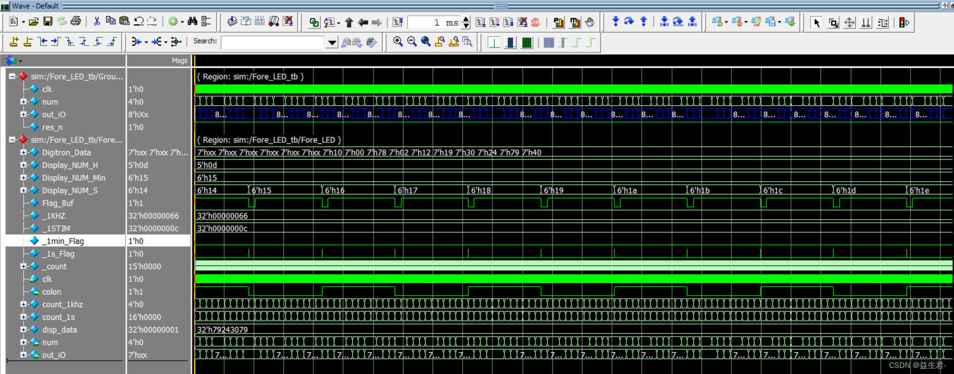
modusim软件仿真波形
最后说明:
引脚约束等读者自行按照自己的开发板选择管脚即可,注意引脚的电平即可


 1018
1018

 被折叠的 条评论
为什么被折叠?
被折叠的 条评论
为什么被折叠?
 到【灌水乐园】发言


