


基于FPGA使用Verilog编写驱动数码管单个显示例程
硬件使用类似说明
- FPGA使用国产GW的YANG NANO 9K开发板
- 数码管使用四位共阳数码管
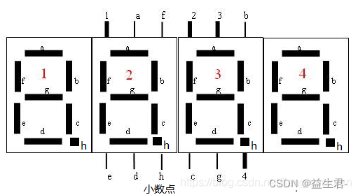
图中1-4数字代表数码管的段选,a-g为单个段的位选择,h表示数码管的小数点。 - 复位按键在开发板上所定义
共阳数码管显示1-F所对应的段选码表:
{0xc0,0xf9,0xa4,0xb0,0x99,0x92,0x82,0xf8,0x80,0x90,0x88,0x83,0xc6,0xa1,0x86,0x8e}; //共阳数码管  1- F  无小数点
{0x40,0x79,0x24,0x30,0x19,0x12,0x02,0x78, 0x00,0x10,0x08,0x03,0x46,0x21,0x06,0x0e};共阳数码管段选码表,有小数点
共阴数码管
{0x3f,0x06,0x5b,0x4f,0x66,0x6d,0x7d,0x07,0x7f,0x6f,0x77,0x7c,0x39,0x5e,0x79,0x71};//共阴数码管段选表,无小数点:
{0xbf,0x86,0xdb,0xcf,0xe6,0xed,0xfd,0x87,0xff,0xef,0xf7,0xfc,0xb9,0xde,0xf9,0xf1};共阴数码管段选表,有小数点:
HDL顶层测试程序
//四位数码管显示实验

module LEDS_Top (
        input  clk, //27Mhz  计数一个时间 = 1/27*10^6(s) = 37ns  1s计数个数 27,027,027
        input  rest,
        output reg [7:0] out_IO
    );

    parameter Delay_1s = 27_027_027;
    reg [24:0] count;
    reg [3:0] out_7IO;

    always @(posedge clk) begin
        if (rest == 0)
            count <= 0;
        else if(count != Delay_1s-1)
            count <=count+25'd1;
        else
            count<=0;
    end
//共阳数码管  {0xc0,0xf9,0xa4,0xb0,0x99,0x92,0x82,0xf8,0x80,0x90,0x88,0x83,0xc6,0xa1,0x86,0x8e};
    always @(posedge clk) begin
        if (rest == 0)
            out_7IO <= 0;
        else if(count == Delay_1s-1)
            out_7IO <= out_7IO+4'd1;
        else if(out_7IO == 4'd10) begin
            out_7IO<=0;

        end

        else begin
            case (out_7IO)
                4'd0:
                    out_IO<= 8'hc0;
                4'd1:
                    out_IO<= 8'hF9;
                4'd2:
                    out_IO<= 8'hA4;
                4'd3:
                    out_IO<= 8'hB0;
                4'd4:
                    out_IO<= 8'h99;
                4'd5:
                    out_IO<= 8'h92;
                4'd6:
                    out_IO<= 8'h82;
                4'd7:
                    out_IO<= 8'hF8;
                4'd8:
                    out_IO<= 8'h80;
                4'd9:
                    out_IO<= 8'h90;
                default:
                    out_IO<= 8'h0;

            endcase
        end
    end
endmodule
源码说明:
    input  clk, //27Mhz  计数一个时间 = 1/27*10^6(s) = 37ns  1s计数个数 27,027,027
    input  rest,//复位按键
    output [7:0] out_IO//输出引脚
Testbench测试文件
`timescale 1ns/1ns

module LEDS_Top_tb ();

    reg clk;
    reg rest;

    wire [6:0] out_IO;

    initial begin
        clk =0;
        rest =0;
        #20;
        rest = 0;
        #100;
        rest = 1 ;

    end

    LEDS_Top #(
                .Delay_1s(500)
            )LEDS_Top_Init(
                .clk(clk), //27Mhz  计数一个时间 = 1/27*10^6(s) = 37ns  1s计数个数 27,027,027
                .rest(rest),
                .out_IO(out_IO)
                 //output [3:0] cs;
            );

    always #10 clk = ~clk;


//随机产生数   {$random}%2 0-1的数

endmodule
通过 Modelsim 查看测试波形是否正确
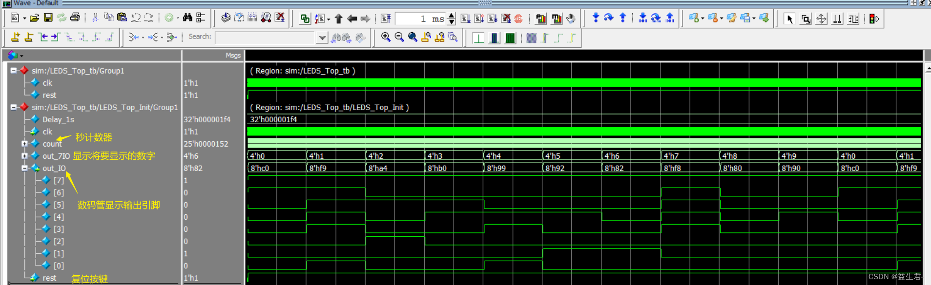
最后说明一下
此程序实现单为数码管每一秒计数器加一,到9自动再重0开始计数,以此往复循环


 9523
9523

 被折叠的 条评论
为什么被折叠?
被折叠的 条评论
为什么被折叠?
 到【灌水乐园】发言


