


目标:
了解如何使用URDF文件创建一个机器人模型,然后使用xacro文件优化该模型,并且放置到rviz+ArbotiX或Gazebo仿真环境中,以实现丰富的ROS功能。
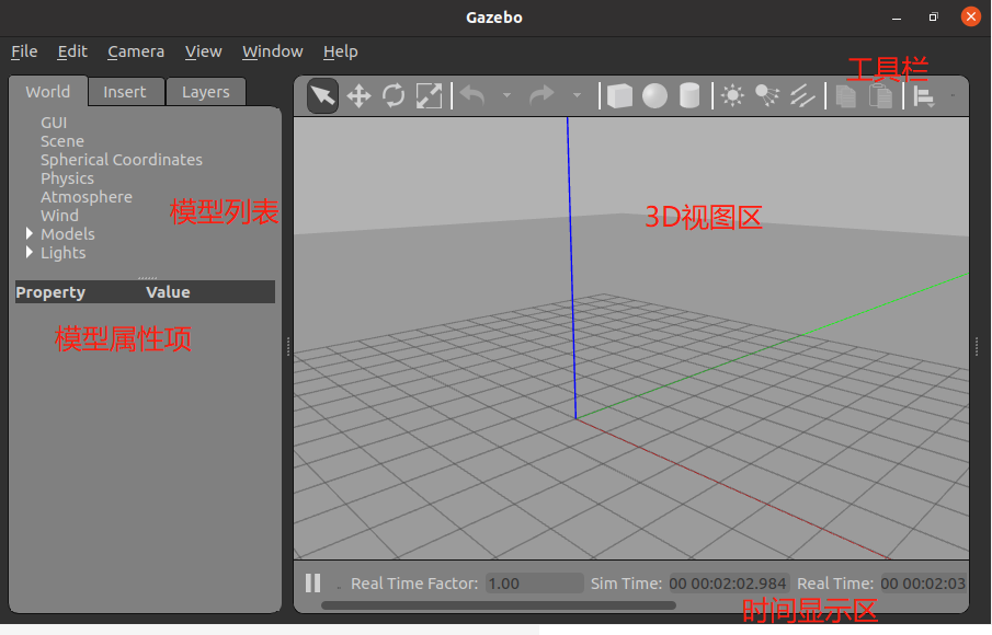
4.5 Gazebo仿真环境
1)动力学仿真:支持多种高性能的物理引擎,如ODE、Bullet、SimBody、DART等。2)三维可视化环境:支持显示逼真的三维环境,包括光线、纹理、影子。
3)传感器仿真:支持传感器数据的仿真,同时可以仿真传感器噪声。
4)可扩展插件:用户可以定制化开发插件以扩展Gazebo的功能,满足个性化的需求。
5)多种机器人模型:官方提供PR2、Pioneer2 DX、TurtleBot等机器人模型,当然也可以使用自己创建的机器人模型。
6)TCP/IP传输:Gazebo的后台仿真处理和前台图形显示可以通过网络通信实现远程仿真。
7)云仿真:Gazebo仿真可以在Amazon、Softlayer等云端运行,也可以在自己搭建的云服务器上运行。
8)终端工具:用户可以使用Gazebo提供的命令行工具在终端实现仿真控制。
4.5.2 安装并运行Gazebo
如果已经安装了桌面完整版的ROS,那么可以直接跳过这一步,否则,请使用以下命令进行安装:
sudo apt-get install ros-noetic-gazebo-ros-pkgs ros-noetic-gazebo-ros-control -y
安装完成后,在终端中使用如下命令启动ROS和Gazebo:
roscore
rosrun gazebo_ros gazebo
——————
报错:
rosrun gazebo_ros gazebo

Command 'rosrun' not found, but can be installed with:

sudo apt install rosbash
重新安装
sudo apt install ros-noetic-desktop-full
——————

验证Gazebo是否与ROS系统成功连接,可以查看ROS的话题列表:
rostopic list
rosservice list
出现 gazebo 相关内容
gazebo --version
Gazebo multi-robot simulator, version 11.11.0
4.5.3 构建仿真环境
1.直接插入模型
模型的加载需要连接国外网站,为了保证模型顺利加载,可以提前将模型文件下载并放置到本地路径~/.gazebo/models下,模型文件的下载地址:https://bitbucket.org/osrf/gazebo_models/downloads/。
2.Building Editor
第二种方法是使用Gazebo提供的Building Editor工具手动绘制地图。在Gazebo菜单栏中选择Edit→Building Editor,可以打开如图4-26所示的Building Editor界面。选择左侧的绘制选项,然后在上侧窗口中使用鼠标绘制,下侧窗口中即可实时显示绘制的仿真环境。
第6章 机器人建模与仿真

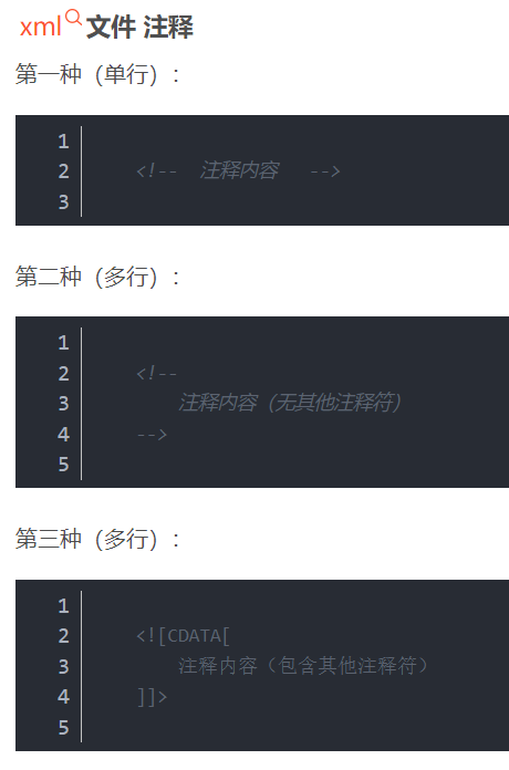
URDF(Unified Robot Description Format,统一机器人描述格式)是ROS中一个非常重要的机器人模型描述格式,ROS同时也提供URDF文件的C++解析器,可以解析URDF文件中使用XML格式描述的机器人模型。
URDF文件中常用的XML标签
6.1.1 <link> 标签 【刚体 杆 腿】
<link>标签用于描述机器人某个刚体部分的外观和物理属性,包括尺寸(size)、颜色(color)、形状(shape)、惯性矩阵(inertial matrix)、碰撞参数(collision properties)等。
<link name="<link name>">
<inertial> . . . . . . </inertial>
    <visual> . . . . . . </visual>
    <collision> . . . . . . </collision>
 </link>
<visual>标签用于描述机器人link部分的外观参数,
<inertial>标签用于描述link的惯性参数,
<collision>标签用于描述link的碰撞属性。
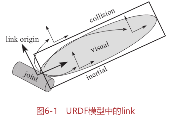
从上图可以看到,检测碰撞的link区域大于外观可视的区域,这就意味着只要有其他物体与collision区域相交,就认为link发生碰撞。
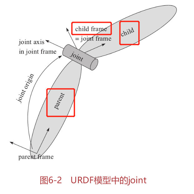
6.1.2 <joint>标签 【连接两个刚体link】
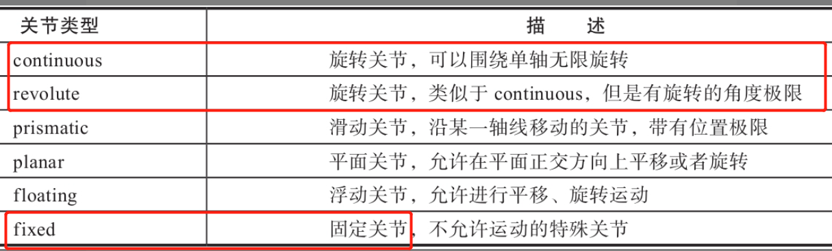
<joint>标签用于描述机器人关节的运动学和动力学属性,包括关节运动的位置和速度限制。根据机器人的关节运动形式,可以将其分为六种类型
<joint name="<name of the joint>">
    <parent link="parent_link"/>
    <child link="child_link"/>
    <calibration .... />
    <dynamics damping ..../>
    <limit effort .... />
    ....
</joint>
必须指定joint的parent link和child link
·<calibration>:关节的参考位置,用来校准关节的绝对位置。·<dynamics>:用于描述关节的物理属性,例如阻尼值、物理静摩擦力等,经常在动力学仿真中用到。
·<limit>:用于描述运动的一些极限值,包括关节运动的上下限位置、速度限制、力矩限制等。
·<mimic>:用于描述该关节与已有关节的关系。·<safety_controller>:用于描述安全控制器参数。
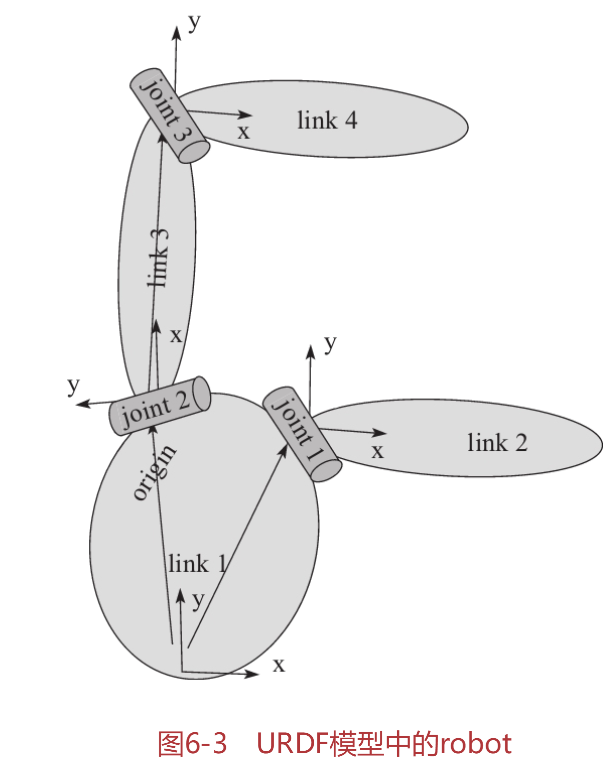
6.1.3 <robot>标签
<robot>是完整机器人模型的最顶层标签,<link>和<joint>标签都必须包含在<robot>标签内。如图6-3所示,一个完整的机器人模型由一系列<link>和<joint>组成。
<robot name="<name of the robot>">
    <link> ....... </link>
    <link> ....... </link>
    <joint> ....... </joint>
    <joint> ....... </joint>
</robot>
6.1.4 <gazebo>标签
<gazebo>标签用于描述机器人模型在Gazebo中仿真所需要的参数,包括机器人材料的属性、Gazebo插件等。该标签不是机器人模型必需的部分,只有在Gazebo仿真时才需加入。
<gazebo reference="link_1">
    <material>Gazebo/Black</material>
</gazebo>
6.2 创建机器人URDF模型
在ROS中,机器人的模型一般放在RobotName_description功能包下。
6.2.1 创建机器人描述功能包
这里直接下载 配套源码了
下载仓库特定文件夹的网站
github仓库链接
这里下载Gazebo仿真相关的
https://github.com/huchunxu/ros_exploring/tree/master/robot_mrobot

mrobot_description功能包中包含urdf、meshes、launch和config四个文件夹。
·urdf:用于存放机器人模型的URDF或xacro文件。
·meshes:用于放置URDF中引用的模型渲染文件。
·launch:用于保存相关启动文件。
·config:用于保存rviz的配置文件。
2、创建机器人描述功能包 mrobot_description
进入代码空间,使用catkin_create_pkg命令创建功能包
# 命令格式
catkin_create_pkg <package_name> [depend1] [depend2] [depend3]
cd ~/catkin_ws/src
catkin_create_pkg mrobot_description urdf xacro
回到工作空间的根目录下进行编译(命令行cd),并且设置环境变量
cd ~/catkin_ws
catkin_make -DCATKIN_WHITELIST_PACKAGES="mrobot_description"
source ~/catkin_ws/devel/setup.bash
3、创建URDF模型
mrobot_description/urdf/mrobot_chassis.urdf
urdf文件 检查
URDF提供了一些命令行工具,可以帮助我们检查、梳理模型文件,需要在终端中独立安装:
sudo apt-get install liburdfdom-tools
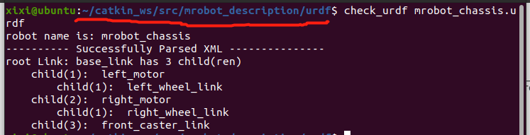
然后使用check_urdf命令对mrobot_chassis.urdf文件进行检查:
check_urdf mrobot_chassis.urdf
还可以使用urdf_to_graphiz命令查看URDF模型的整体结构:
urdf_to_graphiz mrobot_chassis.urdf
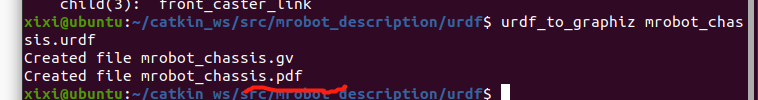
用火狐浏览器打开查看
firefox mrobot_chassis.pdf

6.2.4 在rviz中显示模型
mrobot_description/launch/display_mrobot_chassis_urdf.launch
cd ~/catkin_ws
catkin_make
source ~/catkin_ws/devel/setup.bash
【Tips】 只编译特定功能包
在 双引号 里添加要编译的1-N个包
catkin_make -DCATKIN_WHITELIST_PACKAGES=""
打开终端运行该launch文件
roslaunch mrobot_description display_mrobot_chassis_urdf.launch
——————
报错:
process[joint_state_publisher-1]: started with pid [30971]
ERROR: cannot launch node of type [robot_state_publisher/state_publisher]: Cannot locate node of type [state_publisher] in package [robot_state_publisher]. Make sure file exists in package path and permission is set to executable (chmod +x)
process[rviz-3]: started with pid [30972]

重新编译
————————

这个机器人底盘模型有7个link和6个joint。7个link包括1个机器人底板、2个电机、2个驱动轮和2个万向轮;6个joint负责将驱动轮、万向轮、电机安装到底板上,并设置相应的连接方式。
6.3 改进的URDF模型 —— xacro
针对URDF模型产生了另外一种精简化、可复用、模块化的描述形式——xacro
xacro是URDF的升级版,模型文件的后缀名由.urdf变为.xacro,而且在模型<robot>标签中需要加入xacro的声明:
<?xml version="1.0"?>
<robot name="robot_name" xmlns:xacro="http://www.ros.org/wiki/xacro>"
xacro提供了一种常量属性的定义方式
<xacro:property name="M_PI" value="3.14159"/>
当需要使用该常量时,使用如下语法调用即可:
<origin xyz="0 0 0" rpy="${M_PI/2} 0 0" />
如果改动机器人模型,只需要修改这些参数即可,十分方便。
- 类似于编程语言的 常量定义
2.调用数学公式 ${}
<origin xyz="0 ${(motor_length+wheel_length)/2} 0" rpy="0 0 0"/>
3.使用宏定义
在xacro中,相同的模型就可以通过定义一种宏定义模块的方式来重复使用。
<xacro:macro name="mrobot_standoff_2in" params="parent number x_loc y_loc z_loc">
    <joint name="standoff_2in_${number}_joint" type="fixed">
        <origin xyz="${x_loc} ${y_loc} ${z_loc}" rpy="0 0 0" />
        <parent link="${parent}"/>
        <child link="standoff_2in_${number}_link" />
    </joint>
    <link name="standoff_2in_${number}_link">
        <inertial>
            <mass value="0.001" />
            <origin xyz="0 0 0" />
            <inertia ixx="0.0001" ixy="0.0" ixz="0.0"
                     iyy="0.0001" iyz="0.0"
                     izz="0.0001" />
        </inertial>
        <visual>
            <origin xyz=" 0 0 0 " rpy="0 0 0" />
            <geometry>
                <box size="0.01 0.01 0.07" />
            </geometry>
            <material name="black">
                <color rgba="0.16 0.17 0.15 0.9"/>
            </material>
        </visual>
        <collision>
            <origin xyz="0.0 0.0 0.0" rpy="0 0 0" />
            <geometry>
                <box size="0.01 0.01 0.07" />
            </geometry>
        </collision>
    </link>
</xacro:macro>
以上宏定义中包含五个输入参数:joint的parent link,支撑柱的序号,支撑柱在x、y、z三个方向上的偏移。需要该宏模块时,使用如下语句调用,设置输入参数即可:
<mrobot_standoff_2in parent="base_link" number="4" x_loc="${standoff_x/2}" y_loc="${standoff_y}" z_loc="${plate_height/2}"/>
类似于 函数调用
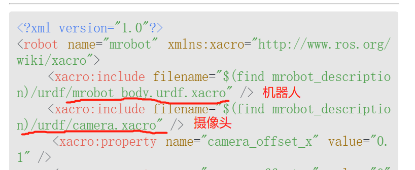
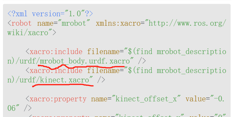
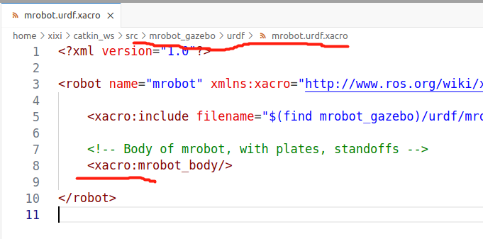
改进后的机器人模型文件是mrobot_description/urdf/mrobot.urdf.xacro
<?xml version="1.0"?>
<robot name="mrobot" xmlns:xacro="http://www.ros.org/wiki/xacro">
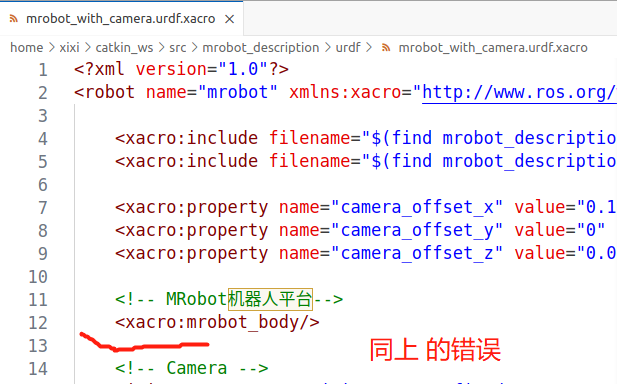
<xacro:include filename="$(find mrobot_description)/urdf/mrobot_body.urdf.xacro" /> <!--include-->
<!-- MRobot机器人平台 noetic 需要添加 xacro:-->
<xacro:mrobot_body/> <!- -使用被包含文件中的 模块了。-->
</robot>
后续在机器人模型上装配camera、Kinect、rplidar,只需要修改这里的mrobot.urdf.xacro即可。
6.3.4 显示.xacro 模型
2.直接调用xacro文件解析器
在launch文件中使用如下语句进行配置:
<arg name="model" default="$(find xacro)/xacro --inorder '$(find mrobot_description)/urdf/mrobot.urdf.xacro'" />
<param name="robot_description" command="$(arg model)" />
mrobot_description/launch/display_mrobot.launch
cd ~/catkin_ws
catkin_make -DCATKIN_WHITELIST_PACKAGES="mrobot_description"
source ~/catkin_ws/devel/setup.bash
roscore
roslaunch mrobot_description display_mrobot.launch
——————
报错:
[ERROR] [1697388543.187372261]: No link elements found in urdf file
[robot_state_publisher-2] process has died [pid 2727, exit code 1, cmd /opt/ros/noetic/lib/robot_state_publisher/robot_state_publisher __name:=robot_state_publisher __log:=/home/xixi/.ros/log/98026536-6b78-11ee-8243-677912ec5555/robot_state_publisher-2.log].
log file: /home/xixi/.ros/log/98026536-6b78-11ee-8243-677912ec5555/robot_state_publisher-2*.log
[ERROR] [1697388546.817232894]: No link elements found in urdf file
代码有误,修改即可

——————————
——————
1.将xacro文件转换成URDF文件
使用如下命令可以将xacro文件转换成URDF文件:
rosrun xacro xacro.py mrobot.urdf.xacro > mrobot.urdf
当前目录下会生成一个转化后的URDF文件,然后使用上面介绍的launch文件可将该URDF模型显示在rviz中。
6.4 添加传感器模型
6.4.1 添加摄像头
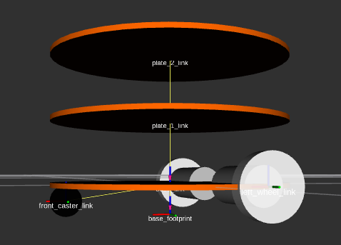
笔者仿照真实摄像头画了一个长方体,以此代表摄像头模型。对应的模型文件是mrobot_description/urdf/camera.xacro:
然后还需要创建一个顶层xacro文件,把机器人和摄像头这两个模块拼装在一起。顶层xacro文件mrobot_description/urdf/mrobot_with_camera.urdf.xacro
运行如下命令,在rviz中查看安装有摄像头的机器人模型
roslaunch mrobot_description display_mrobot_with_camera.launch
也可以在Solidworks等软件中创建更加形象、具体的传感器模型,然后转换成URDF模型格式装配到机器人上。
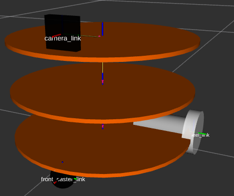
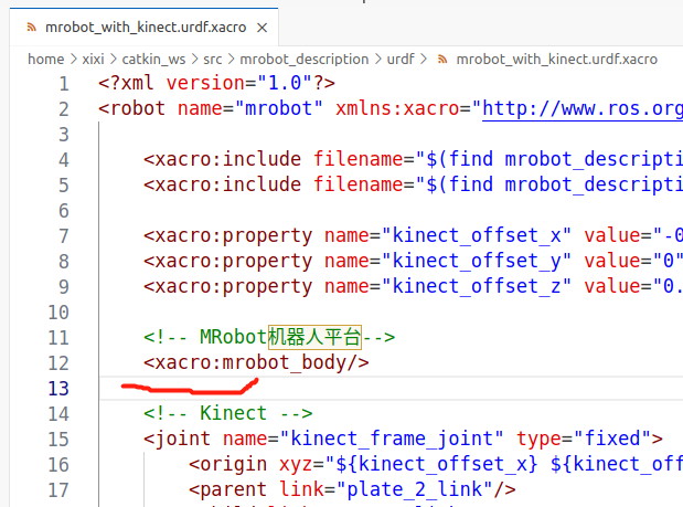
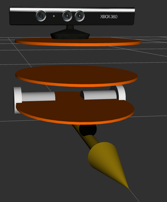
6.4.2 添加Kinect
Kinect是一种常用的RGB-D摄像头,三维模型文件kinect.dae可以在TurtleBot功能包中找到。
Kinect模型描述文件mrobot_description/urdf/kinect.xacro
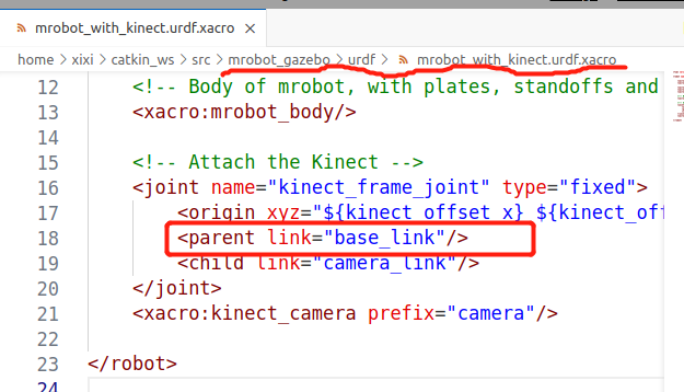
然后将Kinect和机器人拼装到一起,顶层xacro文件mrobot_description/launch/mrobot_with_kinect.urdf.xacro
运行如下命令,即可在rviz中看到安装有Kinect的机器人模型了
roslaunch mrobot_description display_mrobot_with_kinect.launch
先修正 之前类似的错误

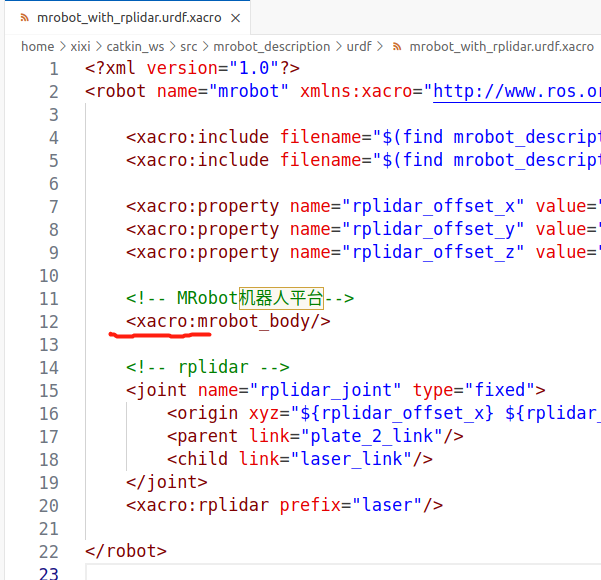
6.4.3 添加激光雷达
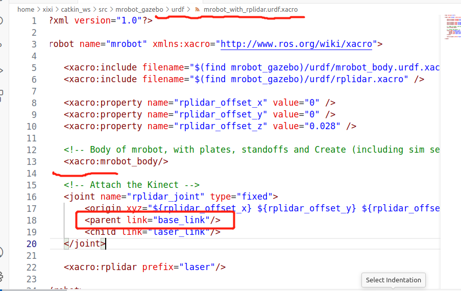
激光雷达的模型文件mrobot_description/urdf/rplidar.xacro,顶层装配文件为mrobot_description/launch/mrobot_with_rplidar.urdf.xacro。
运行以下命令,即可看到安装有激光雷达的机器人模型
roslaunch mrobot_description display_mrobot_with_laser.launch ## 改动了
RLException: [display_mrobot_with_rplidar.launch] is neither a launch file in package [mrobot_description] nor is [mrobot_description] a launch file name
The traceback for the exception was written to the log file
这里是 源码的 launch 文件命名 和 书里不一致。改成源码的即可。或重命名 源码里的文件display_mrobot_with_laser.launch 为 display_mrobot_with_rplidar.launch
可能 解决参考链接
6.5 基于ArbotiX和rviz的仿真器 【实现机器人在rviz中运动】
ArbotiX是一款控制电机、舵机的控制板,并提供相应的ROS功能包。
提供一个差速控制器,通过接收速度控制指令更新机器人的joint状态,从而帮助我们实现机器人在rviz中的运动。
6.5.1 安装ArbotiX
查看 该 功能包 是否已在ROS里
rospack find arbotix
git clone https://github.com/vanadiumlabs/arbotix_ros.git
直接下载了。。。这是一个功能包,所以放到 ~/catkin_ws/src 里
编译
cd ~/catkin_ws
catkin_make -DCATKIN_WHITELIST_PACKAGES="arbotix_ros-noetic-devel"
source ~/catkin_ws/devel/setup.bash
使用如下命令安装缺失的功能包
注意ROS版本
sudo apt-get install ros-noetic-arbotix-python -y
安装完了之后设置一下环境变量(如果你已经把设置环境变量的命令写入~/.bashrc中,就不需要了)
source ~/catkin_ws/devel/setup.bash
6.5.2 配置ArbotiX控制器
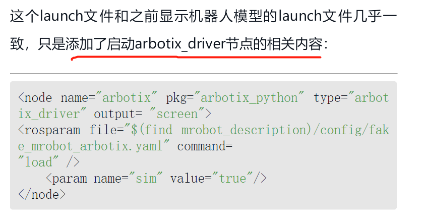
只需要创建一个启动ArbotiX节点的launch文件,再创建一个控制器相关的配置文件即可。
1.创建launch文件
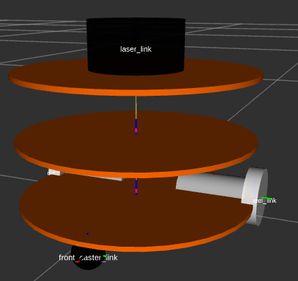
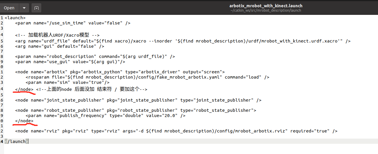
以装配了Kinect的机器人模型为例,创建启动ArbotiX节点的launch文件mrobot_description/launch/arbotix_mrobot_with_kinect.launch
2.创建配置文件
配置文件mrobot_description/config/fake_mrobot_arbotix.yaml
6.5.3 运行仿真环境
cd ~/catkin_ws
catkin_make -DCATKIN_WHITELIST_PACKAGES="mrobot_description"
source ~/catkin_ws/devel/setup.bash
roscore
roslaunch mrobot_description arbotix_mrobot_with_kinect.launch
——————
报错1:
[arbotix-1] process has died [pid 2527, exit code 1, cmd /home/xixi/catkin_ws/src/arbotix_ros-noetic-devel/arbotix_python/bin/arbotix_driver __name:=arbotix __log:=/home/xixi/.ros/log/72f71cd8-6bfe-11ee-94ca-337d47f998b4/arbotix-1.log].
log file: /home/xixi/.ros/log/72f71cd8-6bfe-11ee-94ca-337d47f998b4/arbotix-1*.log
源码有误
报错2:
raceback (most recent call last):
  File "/home/xixi/catkin_ws/src/arbotix_ros-noetic-devel/arbotix_python/bin/arbotix_driver", line 33, in <module>
    from arbotix_msgs.msg import *
ModuleNotFoundError: No module named 'arbotix_msgs'

[arbotix-1] process has died [pid 4164, exit code 1, cmd /home/xixi/catkin_ws/src/arbotix_ros-noetic-devel/arbotix_python/bin/arbotix_driver __name:=arbotix __log:=/home/xixi/.ros/log/963bd808-6c1e-11ee-94ca-337d47f998b4/arbotix-1.log].
log file: /home/xixi/.ros/log/963bd808-6c1e-11ee-94ca-337d47f998b4/arbotix-1*.log
解决办法:使用如下命令安装缺失的功能包
注意ROS版本
sudo apt-get install ros-noetic-arbotix-python -y
安装完了之后设置一下环境变量(如果你已经把设置环境变量的命令写入~/.bashrc中,就不需要了)
source ~/catkin_ws/devel/setup.bash
————————————
————————无关 Start ————————
查看python 版本
python --version
Python 3.8.10
whereis python3
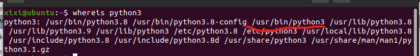
【Tips】建立路径间的链接 Linux命令
sudo ln -s /usr/bin/python3 另一路径
————————无关 End ————————
——————
运行键盘控制程序,然后在终端中根据提示信息点击键盘,就可以控制rviz中的机器人模型运动了。
是另一个功能包,需要先编译
cd ~/catkin_ws
catkin_make -DCATKIN_WHITELIST_PACKAGES="mrobot_teleop"
source ~/catkin_ws/devel/setup.bash
roslaunch mrobot_teleop mrobot_teleop.launch
——————
报错1:
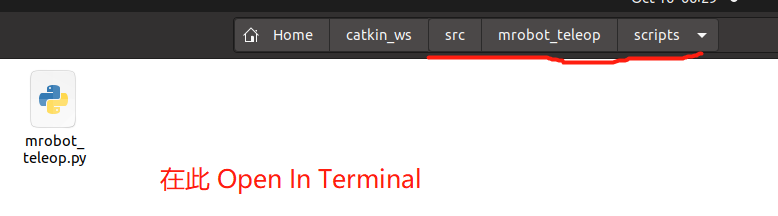
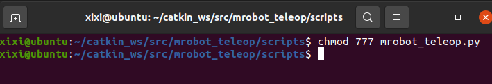
ERROR: cannot launch node of type [mrobot_teleop/mrobot_teleop.py]: Cannot locate node of type [mrobot_teleop.py] in package [mrobot_teleop]. Make sure file exists in package path and permission is set to executable (chmod +x)
转到→ mrobot_teleop
chmod 777 mrobot_teleop.py
chmod 777 mrobot_teleop.py
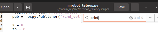
报错2:
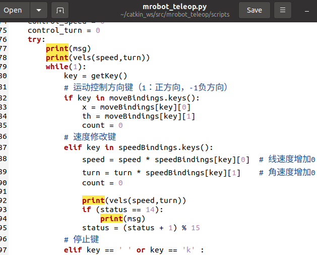
  File "/home/xixi/catkin_ws/src/mrobot_teleop/scripts/mrobot_teleop.py", line 77
    print msg
          ^
SyntaxError: Missing parentheses in call to 'print'. Did you mean print(msg)?
据说 这本书的作者 当时使用的Python版本是2.7。所以是python2的语法
改成Python3的语法即可
注意 一共5处,都要改
——————

如何使用URDF文件创建一个机器人模型,然后使用xacro文件优化该模型,并且放置到rviz+ArbotiX或Gazebo仿真环境中,以实现丰富的ROS功能。
6.6 ros_control

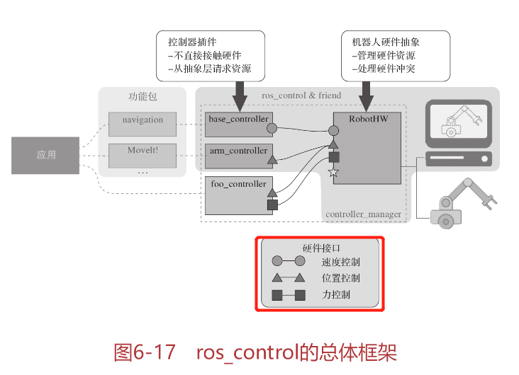
创建控制器的具体方法可以参考wiki:https://github.com/ros-controls/ros_control/wiki/controller_interface

传动系统(Transmission)可以将机器人的关节指令转换成执行器的控制信号。
可以在机器人的URDF模型文件中按照以下方法配置:
<transmission name="simple_trans">
    <type>transmission_interface/SimpleTransmission</type>
    <joint name="foo_joint">
        <hardwareInterface>EffortJointInterface</hardwareInterface>
    </joint>
    <actuator name="foo_motor">
        <mechanicalReduction>50</mechanicalReduction>
        <hardwareInterface>EffortJointInterface</hardwareInterface>
    </actuator>
</transmission>
可以使用如下方式在URDF中设置关节约束(Joint Limits)参数
<joint name="$foo_joint" type="revolute">
    <!-- other joint description elements -->
    <!-- Joint limits -->
    <limit lower="0.0" upper="1.0" effort="10.0"  ="5.0" />
    <!-- Soft limits -->
    <safety_controller k_position="100" k_velocity="10"
                     soft_lower_limit="0.1" soft_upper_limit="0.9" />
</joint>
还有一些参数需要通过YAML配置文件事先加载到参数服务器中,YAML文件的格式如下:
joint_limits:
    foo_joint:
        has_position_limits: true
        min_position: 0.0
        max_position: 1.0
        has_velocity_limits: true
        max_velocity: 2.0
        has_acceleration_limits: true
        max_acceleration: 5.0
        has_jerk_limits: true
        max_jerk: 100.0
        has_effort_limits: true
        max_effort: 5.0
    bar_joint:
        has_position_limits: false # Continuous joint
        has_velocity_limits: true
        max_velocity: 4.0
6.6.6 控制器管理器
1.命令行工具
controller_manager命令的格式为:
rosrun controller_manager controller_manager <command> <controller_name>
支持的
<command>如下:
·load:加载一个控制器。
·unload:卸载一个控制器。
·start:启动控制器。
·stop:停止控制器。
·spawn:加载并启动一个控制器。
·kill:停止并卸载一个控制器。
如果希望查看某个控制器的状态,可以使用如下命令:
rosrun controller_manager controller_manager <command>
支持的
<command>如下:
·list:根据执行顺序列出所有控制器,并显示每个控制器的状态。
·list-types:显示所有控制器的类型。
·reload-libraries:以插件的形式重载所有控制器的库,不需要重新启动,方便对控制器的开发和测试。
·reload-libraries–restore:以插件的形式重载所有控制器的库,并恢复到初始状态。
使用spawner命令一次控制多个控制器:
rosrun controller_manager spawner [--stopped] name1 name2 name3
停止一系列控制器,但是不需要卸载,可以使用如下命令:
rosrun controller_manager unspawner name1 name2 name3
2.launch工具
<launch>
    <node pkg="controller_manager" type="spawner" args="controller_name1 controller_name2" />
</launch>
以上launch文件会加载并启动controller,如果只需加载不必启动,可以使用以下配置:
<launch>
     <node pkg="controller_manager" type="spawner" args="--stopped controller_name1 controller_name2" />
</launch>
3.可视化工具rqt_controller_manager
rosrun rqt_controller_manager rqt_controller_manager
6.7 Gazebo仿真
6.7.1 机器人模型添加Gazebo属性
首先我们需要确保每个link的<inertia>元素已经进行了合理的设置,然后要为每个必要的<link>、<joint>、<robot>设置<gazebo>标签。<gazebo>标签是URDF模型中描述gazebo仿真时所需要的扩展属性。
1、为link添加<gazebo>标签
针对机器人模型,需要对每一个link添加<gazebo>标签,包含的属性仅有material。
material属性的作用与link里<visual>中material属性的作用相同,Gazebo无法通过<visual>中的material参数设置外观颜色,所以需要单独设置,否则默认情况下Gazebo中显示的模型全是灰白色。
<gazebo reference="wheel_${lr}_link">
    <material>Gazebo/Black</material>
</gazebo>
2、添加传动装置 与joint绑定
为了使用ROS控制器驱动机器人,需要在模型中加入<transmission>元素,将传动装置与joint绑定:
<transmission name="wheel_${lr}_joint_trans">
    <type>transmission_interface/SimpleTransmission</type> <!--传动装置类型-->
    <joint name="base_to_wheel_${lr}_joint" />
    <actuator name="wheel_${lr}_joint_motor">
        <hardwareInterface>VelocityJointInterface</hardwareInterface> <!--硬件接口类型:速度控制接口-->
        <mechanicalReduction>1</mechanicalReduction>
    </actuator>
</transmission>
3、添加Gazebo控制器插件 libgazeboXXX.so
Gazebo插件可以根据插件的作用范围应用到URDF模型的<robot>、<link>、<joint>上,需要使用<gazebo>标签作为封装。
(1)为<robot>元素添加插件
<gazebo>
    <plugin name="unique_name" filename="plugin_name.so">
        ... plugin parameters ...
    </plugin>
</gazebo>
(2)为<link>、<joint>标签添加插件
需要设置<gazebo>标签中的reference="x"属性:
<gazebo reference="your_link_name">
    <plugin name=" unique_name " filename="plugin_name.so">
        ... plugin parameters ...
    </plugin>
</gazebo>
Gazebo已经提供了一个用于差速控制的插件libgazebo_ros_diff_drive.so,可以将其应用到现有的机器人模型上。在mrobot_gazebo/urdf/mrobot_body.urdf.xacro文件中添加如下插件声明:
<!-- controller -->
<gazebo>
    <plugin name="differential_drive_controller" filename="libgazebo_ros_diff_drive.so">
        <rosDebugLevel>Debug</rosDebugLevel>
        <publishWheelTF>true</publishWheelTF>
        <robotNamespace>/</robotNamespace>
        <publishTf>1</publishTf>
        <publishWheelJointState>true</publishWheelJointState>
        <alwaysOn>true</alwaysOn>
        <updateRate>100.0</updateRate>
        <legacyMode>true</legacyMode>
        <leftJoint>base_to_wheel_left_joint</leftJoint>
        <rightJoint>base_to_wheel_right_joint</rightJoint>
        <wheelSeparation>${base_link_radius*2}</wheelSeparation>
        <wheelDiameter>${2*wheel_radius}</wheelDiameter>
        <broadcastTF>1</broadcastTF>
        <wheelTorque>30</wheelTorque>
        <wheelAcceleration>1.8</wheelAcceleration>
        <commandTopic>cmd_vel</commandTopic>
        <odometryFrame>odom</odometryFrame>
        <odometryTopic>odom</odometryTopic>
        <robotBaseFrame>base_footprint</robotBaseFrame>
    </plugin>
</gazebo>
在加载差速控制器插件的过程中,需要配置一系列参数,其中比较关键的参数如下。
·<robotNamespace>:机器人的命名空间,插件所有数据的发布、订阅都在该命名空间下。
·<leftJoint>和<rightJoint>:左右轮转动的关节joint,控制器插件最终需要控制这两个joint转动。
·<wheelSeparation>和<wheelDiameter>:这是机器人模型的相关尺寸,在计算差速参数时需要用到。
·<wheelAcceleration>:车轮转动的加速度。
·<commandTopic>:控制器订阅的速度控制指令,ROS中一般都命名为cmd_vel,生成全局命名时需要结合<robotNamespace>中设置的命名空间。
·<odometryFrame>:里程计数据的参考坐标系,ROS中一般都命名为odom。
6.7.2 在Gazebo中显示机器人模型
必要的准备工作:
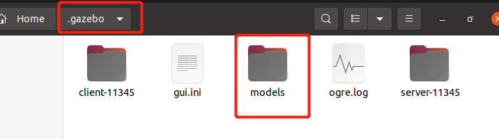
模型的加载需要连接国外网站,为了保证模型顺利加载,可以提前将模型文件下载并放置到本地路径~/.gazebo/models下,模型文件的下载地址:https://github.com/osrf/gazebo_models/。
注意修改文件名称
或
mv gazebo_models/~/.gazebo/models/
创建一个启动文件robot_mrobot/mrobot_gazebo/view_mrobot_gazebo.launch,运行Gazebo,加载机器人模型,并且启动一些必要的节点:
<launch>

    <!-- 设置launch文件的参数 -->
    <arg name="world_name" value="$(find mrobot_gazebo)/worlds/playground.world"/> <!--环境为 playground.world-->
    <arg name="paused" default="false"/>
    <arg name="use_sim_time" default="true"/>
    <arg name="gui" default="true"/>
    <arg name="headless" default="false"/>
    <arg name="debug" default="false"/>

    <!-- 运行Gazebo仿真环境 -->
    <include file="$(find gazebo_ros)/launch/empty_world.launch">
        <arg name="world_name" value="$(arg world_name)" />
        <arg name="debug" value="$(arg debug)" />
        <arg name="gui" value="$(arg gui)" />
        <arg name="paused" value="$(arg paused)"/>
        <arg name="use_sim_time" value="$(arg use_sim_time)"/>
        <arg name="headless" value="$(arg headless)"/>
    </include>

    <!-- 加载机器人模型描述参数 -->
    <param name="robot_description" command="$(find xacro)/xacro --inorder '$(find mrobot_gazebo)/urdf/mrobot.urdf.xacro'" />  <!--机器人 mrobot.urdf.xacro-->

    <!-- 运行joint_state_publisher节点,发布机器人的关节状态  -->
    <node name="joint_state_publisher" pkg="joint_state_publisher" type="joint_state_publisher" ></node>

    <!-- 运行robot_state_publisher节点,发布TF  -->
    <node name="robot_state_publisher" pkg="robot_state_publisher" type="robot_state_publisher"  output="screen" >
        <param name="publish_frequency" type="double" value="50.0" />
    </node>

    <!-- 在gazebo中加载机器人模型-->
    <node name="urdf_spawner" pkg="gazebo_ros" type="spawn_model" respawn= "false" output="screen"
          args="-urdf -model mrobot -param robot_description"/>

</launch>
以上launch文件主要做了两项工作:
1)启动机器人的状态发布节点,同时加载带有Gazebo属性的机器人URDF模型。
2)启动Gazebo,并且将机器人模型加载到Gazebo仿真环境中。
编译功能包
cd ~/catkin_ws
catkin_make -DCATKIN_WHITELIST_PACKAGES="mrobot_gazebo"
source ~/catkin_ws/devel/setup.bash
roscore
启动这个launch文件
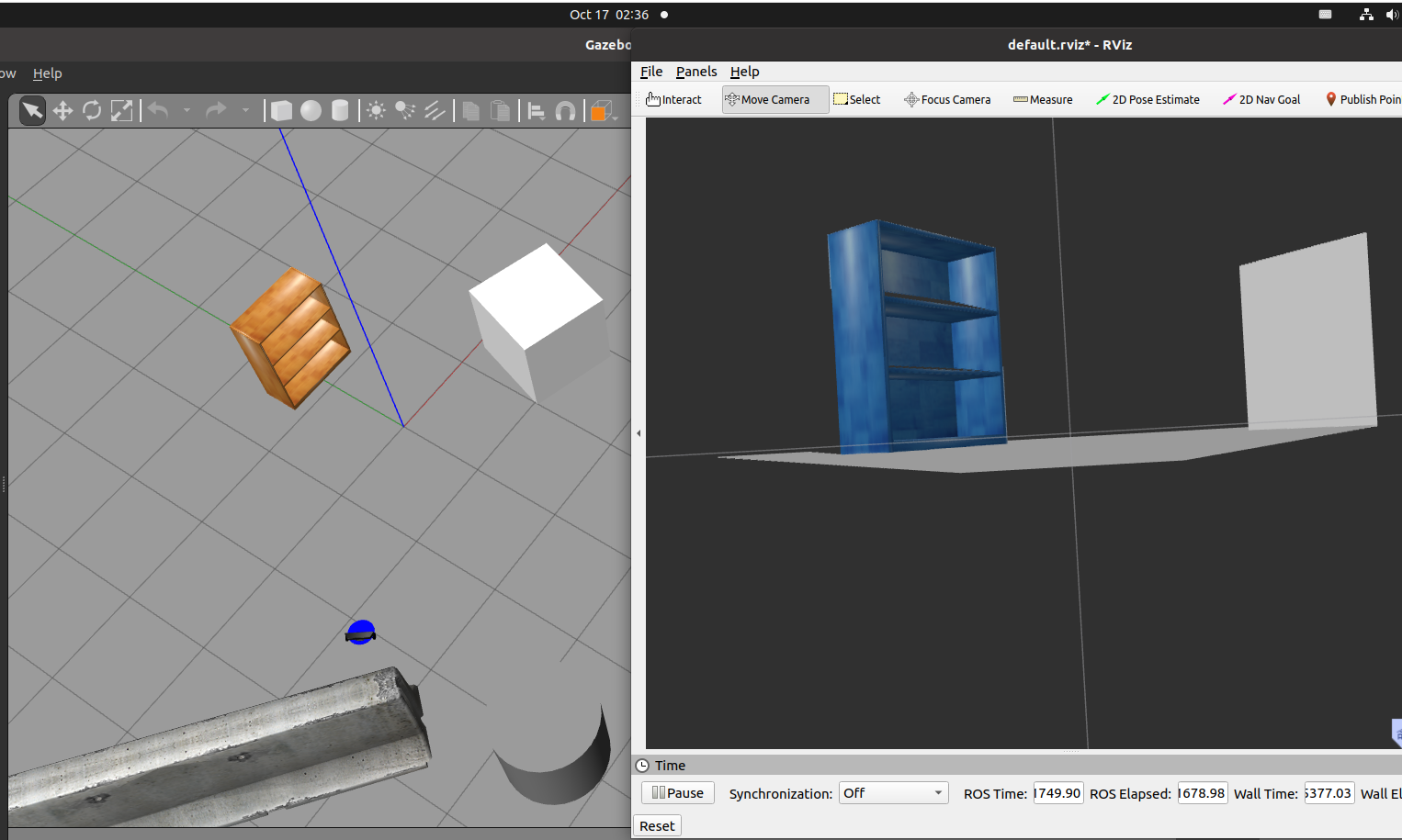
roslaunch mrobot_gazebo view_mrobot_gazebo.launch
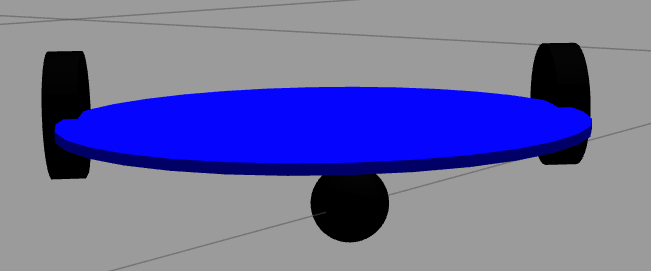
有点像 3轮车
——————————
参考链接
改动:
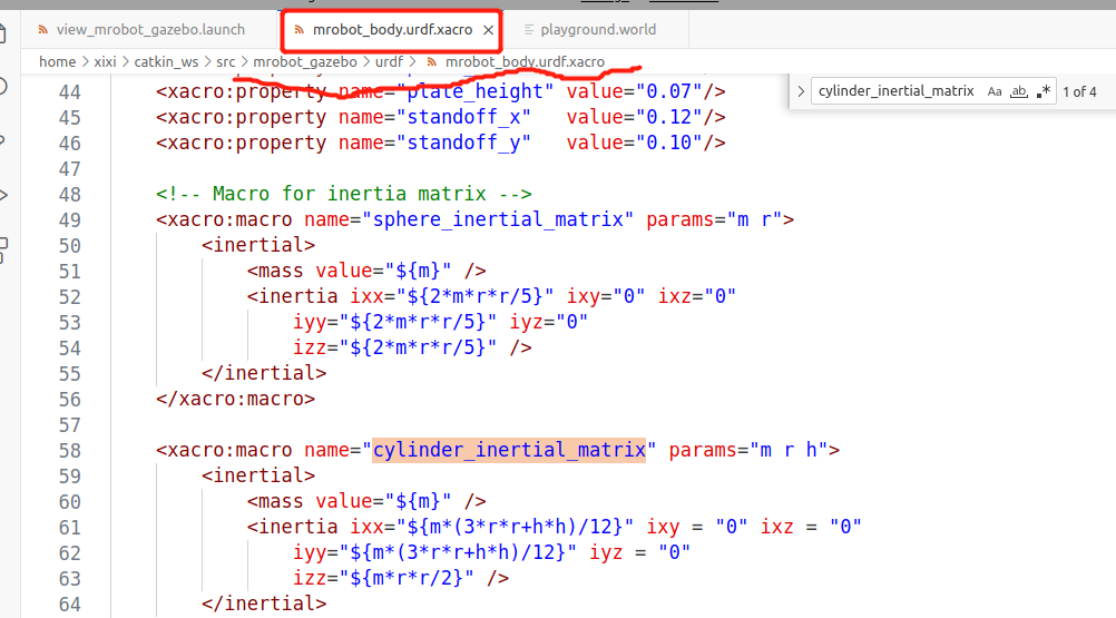
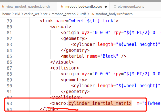
cylinder_inertial_matrix;sphere_inertial_matrix;wheel;caster;前添加xacro:。
cylinder_inertial_matrix 3处(Line93、Line152、Line236)
sphere_inertial_matrix 1处 (Line135)
wheel 2处 (Line257、Line258)
caster 1处 (Line261)
——————
6.7.3 控制机器人在Gazebo中运动
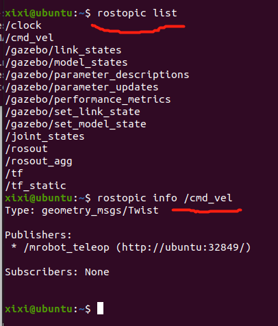
查看系统当前的话题列表
编译功能包
cd ~/catkin_ws
catkin_make -DCATKIN_WHITELIST_PACKAGES="mrobot_teleop"
source ~/catkin_ws/devel/setup.bash
roscore
roslaunch mrobot_teleop mrobot_teleop.launch
i: 直走
o: 左转
u: 右转
6.7.4 摄像头仿真
rviz+ArbotiX搭建的机器人仿真环境中,机器人装配了多种传感器模型,但是这些模型并无法获取任何环境数据。
1.为摄像头模型添加Gazebo插件
复制mrobot_description中的传感器模型到mrobot_gazebo包中,然后在摄像头的模型文件mrobot_gazebo/urdf/camera.xacro中添加<gazebo>的相关标签
<gazebo reference="${prefix}_link">
    <material>Gazebo/Black</material>
</gazebo>

<gazebo reference="${prefix}_link">
    <sensor type="camera" name="camera_node">
        <update_rate>30.0</update_rate>
        <camera name="head">
            <horizontal_fov>1.3962634</horizontal_fov>
            <image>
                <width>1280</width>
                <height>720</height>
                <format>R8G8B8</format>
            </image>
            <clip>
                <near>0.02</near>
                <far>300</far>
            </clip>
            <noise>
                <type>gaussian</type>
                <mean>0.0</mean>
                <stddev>0.007</stddev>
            </noise>
        </camera>
        <plugin name="gazebo_camera" filename="libgazebo_ros_camera.so">
            <alwaysOn>true</alwaysOn>
            <updateRate>0.0</updateRate>
            <cameraName>/camera</cameraName>
            <imageTopicName>image_raw</imageTopicName>
            <cameraInfoTopicName>camera_info</cameraInfoTopicName>
            <frameName>camera_link</frameName>
            <hackBaseline>0.07</hackBaseline>
            <distortionK1>0.0</distortionK1>
            <distortionK2>0.0</distortionK2>
            <distortionK3>0.0</distortionK3>
            <distortionT1>0.0</distortionT1>
            <distortionT2>0.0</distortionT2>
        </plugin>
    </sensor>
</gazebo>
2.运行仿真环境
编译功能包
cd ~/catkin_ws
catkin_make -DCATKIN_WHITELIST_PACKAGES="mrobot_gazebo"
source ~/catkin_ws/devel/setup.bash
roscore
roslaunch mrobot_gazebo view_mrobot_with_camera_gazebo.launch
——————
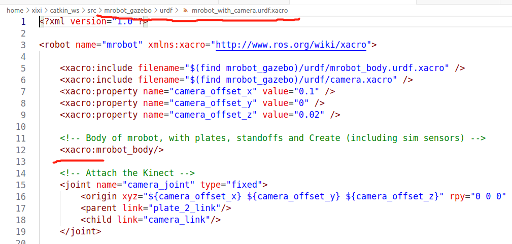
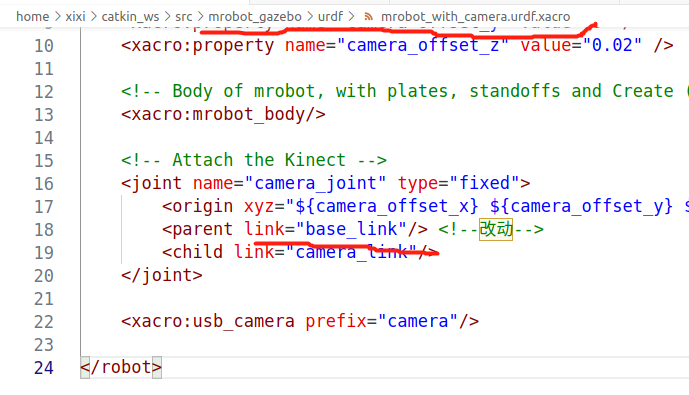
[ERROR] [1697488036.591656431]: Failed to build tree: parent link [plate_2_link] of joint [camera_joint] not found.  This is not valid according to the URDF spec. Every link you refer to from a joint needs to be explicitly defined in the robot description. To fix this problem you can either remove this joint [camera_joint] from your urdf file, or add "<link name="plate_2_link" />" to your urdf file.
[robot_state_publisher-4] process has died [pid 22909, exit code 1, cmd /opt/ros/noetic/lib/robot_state_publisher/robot_state_publisher __name:=robot_state_publisher __log:=/home/xixi/.ros/log/5bed6fe2-6c62-11ee-94ca-337d47f998b4/robot_state_publisher-4.log].
log file: /home/xixi/.ros/log/5bed6fe2-6c62-11ee-94ca-337d47f998b4/robot_state_publisher-4*.log
————————
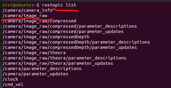
查看当前系统中的话题列表
rostopic list
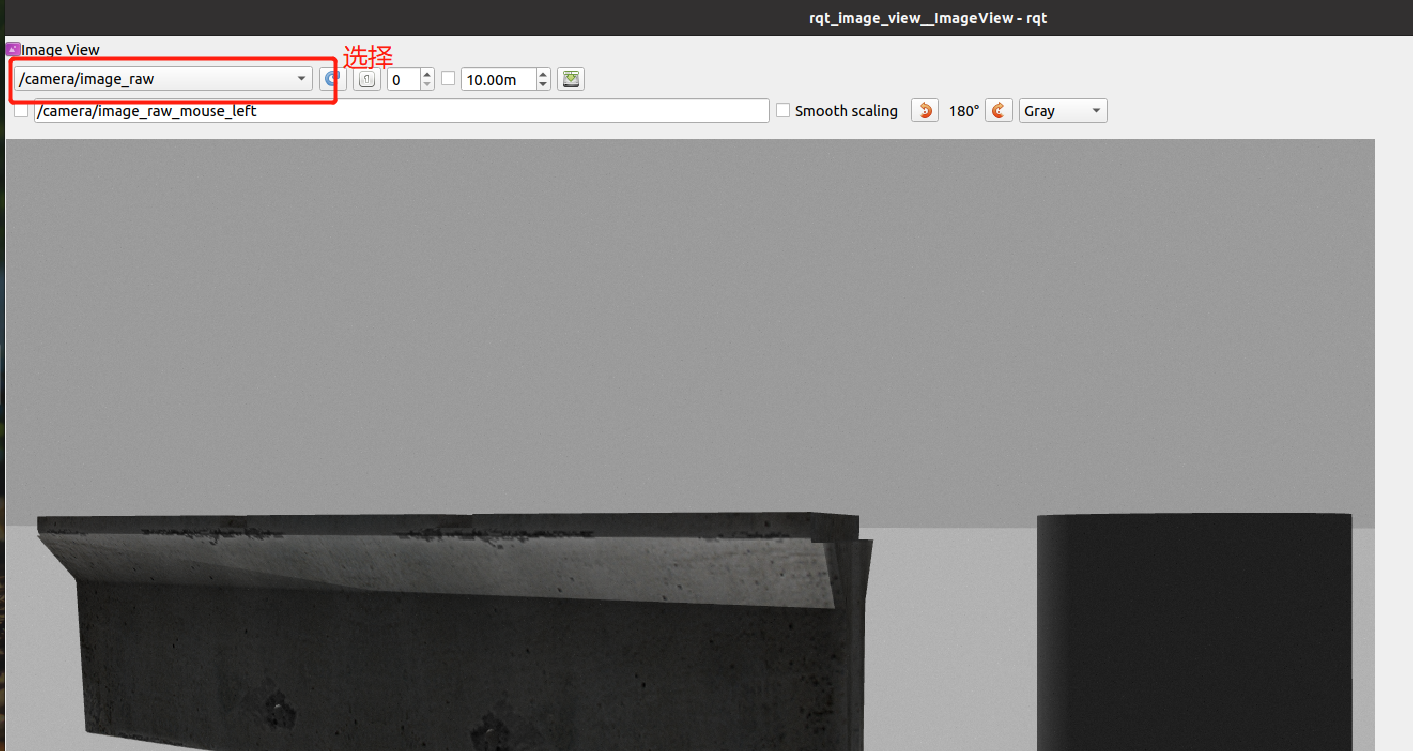
使用rqt工具查看当前机器人眼前的世界:
rqt_image_view
选择仿真摄像头发布的图像话题/camera/image_raw
————————
调整 视线
roslaunch mrobot_teleop mrobot_teleop.launch
byzanz-record -x 72 -y 64 -w 1848 -h 893 -d 20 --delay=5 -c /home/xixi/Mymymy/myGIF/test.gif
6.7.5 Kinect仿真
1.为Kinect模型添加Gazebo插件
2.运行仿真环境
改动:
编译功能包
cd ~/catkin_ws
catkin_make -DCATKIN_WHITELIST_PACKAGES="mrobot_gazebo"
source ~/catkin_ws/devel/setup.bash
roscore
roslaunch mrobot_gazebo view_mrobot_with_kinect_gazebo.launch
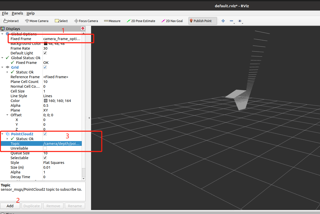
使用如下命令打开rviz,查看Kinect的点云数据:
rosrun rviz rviz
在rviz中需要设置“Fixed Frame”为“camera_frame_optical”,然后添加一个PointCloud2类型的插件,修改插件订阅的话题为/camera/depth/points
————————
调整 视线
roslaunch mrobot_teleop mrobot_teleop.launch
byzanz-record -x 72 -y 64 -w 1848 -h 893 -d 30 --delay=5 -c /home/xixi/Mymymy/myGIF/test.gif

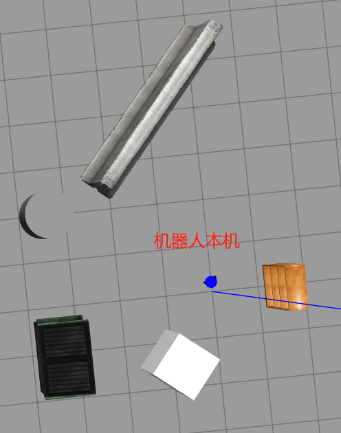
6.7.6 激光雷达仿真
1.为rplidar模型添加Gazebo插件
2.运行仿真环境
改动:
编译功能包
cd ~/catkin_ws
catkin_make -DCATKIN_WHITELIST_PACKAGES="mrobot_gazebo"
source ~/catkin_ws/devel/setup.bash
roscore
roslaunch mrobot_gazebo view_mrobot_with_laser_gazebo.launch
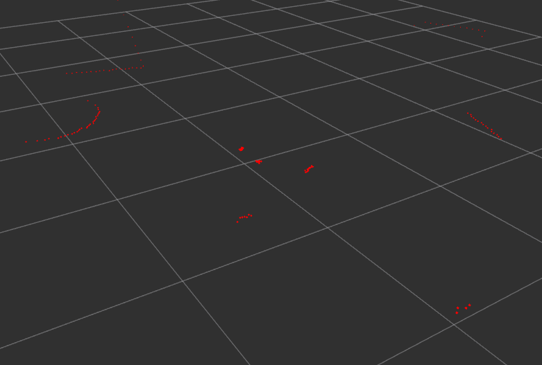
使用如下命令打开rviz,查看rplidar的激光数据:
rosrun rviz rviz
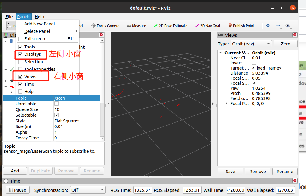
在rviz中设置“Fixed Frame”为“base_footprint”,然后添加一个LaserScan类型的插件,修改插件订阅的话题为“/scan”,就可以看到界面中的激光数据了
调整 位置
roslaunch mrobot_teleop mrobot_teleop.launch
byzanz-record -x 72 -y 64 -w 1848 -h 893 -d 30 --delay=5 -c /home/xixi/Mymymy/myGIF/test.gif

——————— 以下 非正文 ———————
5.3.2 Gazebo仿真器中的环境模型
参考链接
Gazebo仿真器中的模型可以分为两部分,第一部分是环境模型,第二部分是机器人模型。环境模型在Gazebo仿真器中也称为“world”,它的构建比较简单,可以直接使用Gazebo仿真器提供的模型,也可以通过Gazebo仿真器中的模型编辑器构建模型。机器人模型部分内容较多
下载完成后将模型目录拷贝到~/.gazebo目录下并命名为models,即:
mv gazebo_models/ ~/.gazebo/models/
- 由于.gazebo目录为隐藏目录,所以暂时还看不到这个目录,单击右键选择“Show hidden files”显示隐藏文件
将配置好的场景保存为world文件
在URDF文件中最顶层的标签是<robot>标签,用于说明这是一个机器人描述文件,类似于launch文件中<launch>标签。和模型的描述密切相关的标签有两个,即<link>【具有惯性、视觉特征和碰撞属性的刚体。腿】和<joint>
<link>标签的子标签包含<inertial>(惯性特征)、<visual>(可视化特征)以及<collision>(碰撞特征)
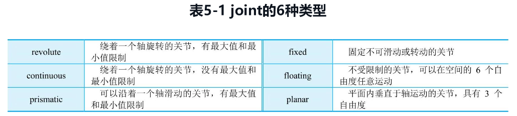
<joint>的子标签中包括了必需的<parent>(父link)、<child>(子link)和可选的<origin>(父子link)坐标变换,以及<axis>(旋转轴)、<calibration>(的参考点)、<dynamics>(<joint>的物理特性)、<limit>(<joint>为受限类型时运动的范围)、<mimic>(模仿已存在的<joint>)、<safety_controller>(安全控制限制)。
通过<robot>、<link>和<joint>三个标签已经可以构成一个基础的机器人模型了


 550
550


 被折叠的 条评论
为什么被折叠?
被折叠的 条评论
为什么被折叠?
 到【灌水乐园】发言


