


 本文详细探讨了插电式混合动力电动汽车(PHEV)在充电过程中产生的热损失问题,重点介绍了逆变器和电池模块的散热设计,以及废热再利用系统的应用。通过Matlab和Simulink的仿真实现,展示了如何有效管理和利用这些热量,以提升能源效率和环保性能。
💥💥💞💞欢迎来到本博客❤️❤️💥💥
🏆博主优势:🌞🌞🌞博客内容尽量做到思维缜密,逻辑清晰,为了方便读者。
⛳️座右铭:行百里者,半于九十。
📋📋📋本文目录如下:🎁🎁🎁
目录
💥1 概述
插电式混合动力电动汽车(PHEV)是一种结合了传统燃油动力和电动动力的先进汽车技术。在PHEV的充电过程中,会产生一定的热量,而本文将重点描述这些热损失的情况。
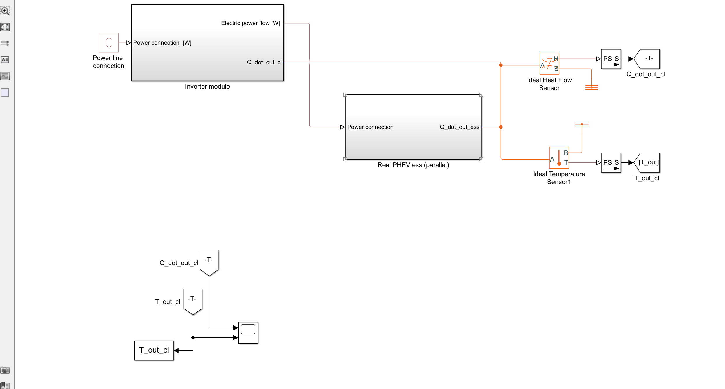
首先,热损失主要出现在PHEV的逆变器和两个电池模块中。这些部件在工作过程中会产生热量,需要及时进行散热以保证其正常运行。为了解决这一问题,PHEV采用了与冷水流并行排列的冷却板来吸收这些热量。通过这种方式,逆变器和电池模块产生的热量能够被有效地散发出去,保持系统的稳定性和安全性。
另外,这些散热板的设计也考虑到了废热的再利用。在散热板吸收了逆变器和电池模块产生的热量后,这些废热会被导入到一个系统中进行再利用。通过混合三个质量流在一起,废热的能量得以最大程度地利用,从而提高了PHEV的能源利用率和环保性能。
总的来说,PHEV在充电过程中的热损失问题得到了有效的解决和利用。通过合理的散热设计和废热再利用系统,PHEV不仅能够保持稳定的运行状态,还能够最大程度地提高能源利用率,为环境保护和可持续发展做出了积极的贡献。
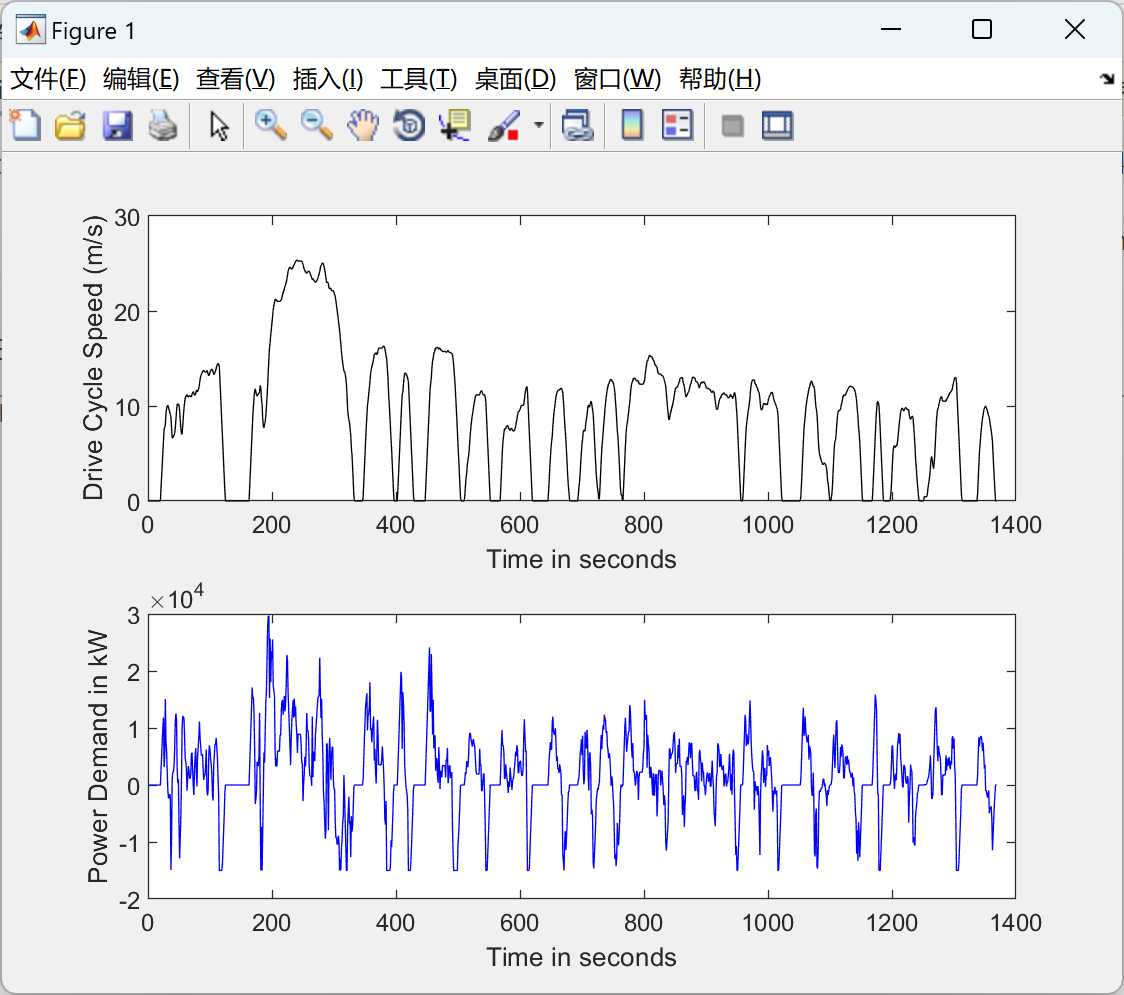
📚2 运行结果

部分代码:
%% General PEV data
%Grid connection
P_l=1500;%Power line connection [W]
%Cooling fluid initial conditions
m_dot=0.5;%[kg/s]
c_p=4200;%[J/kgK] specific heat capacitance H2O
T_i=283.15;%Initial cooling liquid temperature at inverter,
%heat exchanger inlet, and inverter case [K]
T_ambient=300.15;%Initial ambient temperature;
%% Data inverter/charger
%Assumptions base on Delta-q QuiQ datasheet
m_inverter=4;%[kg]
E_inverter=0.83;%Inverter efficiency
%Specific heat capacitance inverter
c_Al=897;%Specific heat capacitance aluminum around room temperature [J/kg K]
c_Co=385;%Specific heat capacity copper [J/kg K]
c_Fe=449;%Specific heat capacity iron [J/kg K]
c_Po=50;%Specific heat capacity of typical Polymers in conductor boards
c_inverter=0.5*c_Al+0.3*c_Co+0.1*c_Fe+0.1*c_Po;
%% Conductive heat transfer parameters for thermal path between inverter and heat exchanger
k_Al=237;%Thermal conductivity aluminum case around room temperature [W/m 癈]
m_case=0.1;%Case weight [kg]
c_case=c_Al;
w_case=0.05;%Width case [m]
A_case=0.246*0.278*0.75;%Assumed surface area of the PEV inverter/charger
w_bond=0.025;%Width bond between case plate and heat exchanger
k_bond=296;%Eutectic bond as it is in chip carriers
k_ideal=2*k_Al;%Assumed ideal thermal conductivity [W/m 癈];
A_ideal=2*A_case;%Assumed ideal conductive heat transfer area [m^2];
%% Cooling plate parameters
%The underlying assumption is a custom made turbo tube liquid cold plate
%adapted to the geometry of the inverter. Assumptions base on Aavid
%Thermalloy Turbo Tube Liquid Cold Plate datasheet
k_Co=401;%Thermal conductivity of copper [W/m 癈] used in the heat exchanger pipes
w_pipe=0.0015;%Thickness of copper pipes app. 1.5mm
Dm=0.01;%Outer diameter of tubes
L=0.75*0.278;%Effective tube length one way [m]
n=10;%number of pipes on cooling plate
A_pipes=1/3*pi*Dm*L*n; %Assumed relevant area for conductive heat transfer as app.
%1/3 of tube surface is facing towards the inverter case
A_plate=A_case-A_pipes; %Case surface less tube diameter*number of tubes*effective
%tube length adapted from inverter case surface
w_plate=0.05;%Assumed thickness extrusion Aluminum plate [m]
V_pipes=pi*(Dm/2)^2*n*L*0.66;%Effective Volume of pipes inside the Aluminum plate profile
V_plate=A_case*w_plate-V_pipes;%Volume Aluminum plate less spacetaken by tubes [m^3]
rho_Al=2710;%[kg/m^3] Density Aluminum plate
m_plate=rho_Al*V_plate;%Mass Aluminum plate
A_bs_bond=2/3*A_pipes/(1/3);%Effective conductive heat transfer surface area of the bond on the backside
A_surface=A_case;%Convective heat transfer area for outside-facing cooling plates under realistic conditions
h_surface=25;%Empirical value for free convection of gases. Source: Cengel, Basics of heat transfer, 2002, S. 26
%% Heat exchange process parameters
U=1000; %[W/m^2 K] Overall heat transfer coefficient steam condenser
%(Cengel, 2002, S. 673)
A_HE=Dm*pi*(L/0.75)*n;%[m^2] Relevant area for convective heat transfer along the whole pipe length
UA=U*A_HE;
NTU=UA/(m_dot*c_p);%Number of transferred units
E=1-exp(-NTU);%Initial heat exchanger efficiency
rho_Co=8920;%Density Copper [kg/m^3]
m_HE=A_HE*w_pipe*rho_Co;
high_efficiency=0.7;%High efficiency option for scenario analysis
%% Energy storage system parameters
E_ess=0.9;%Energy storage system charging efficiency
m_ess=40;%Mass of a single energy storage system [kg]
c_ess=3482;%Specific heat capacitance Lithium [J/kg K]
C_ess=4900;%Energy storage system capacity [Wh] (See Hymotion, L5 Plug-in
%Conversion module for specifications)
PHEV=2;
EV=11;
n_ess=PHEV;%The EV is equipped with 9 conversion modules. Whereas an efficient PHEV
%has 2 conversion modules. n_ess adapts the neccessary charging time
%% Charging patterns
DOD=0.8;%Depth of discharge
NC_ess=DOD*C_ess*n_ess/(E_ess*E_inverter);%Relevant Net capacity energy storage system for charging
D=NC_ess*3600/P_l;%Charging duration [s]
%% Split up heat flow:
m_dot=m_dot/n_ess
🎉3 参考文献
文章中一些内容引自网络,会注明出处或引用为参考文献,难免有未尽之处,如有不妥,请随时联系删除。
[1]刘宝帅.插电式混合动力汽车动力总成控制策略优化研究[D].昆明理工大学[2024-01-29].DOI:CNKI:CDMD:2.1018.715444.
[2]任培林.基于动态规划的PHEV规则控制策略优化设计研究[D].重庆交通大学[2024-01-29].DOI:CNKI:CDMD:2.1018.149776.


 2318
2318


 被折叠的 条评论
为什么被折叠?
被折叠的 条评论
为什么被折叠?
 到【灌水乐园】发言


