


1 基本原理
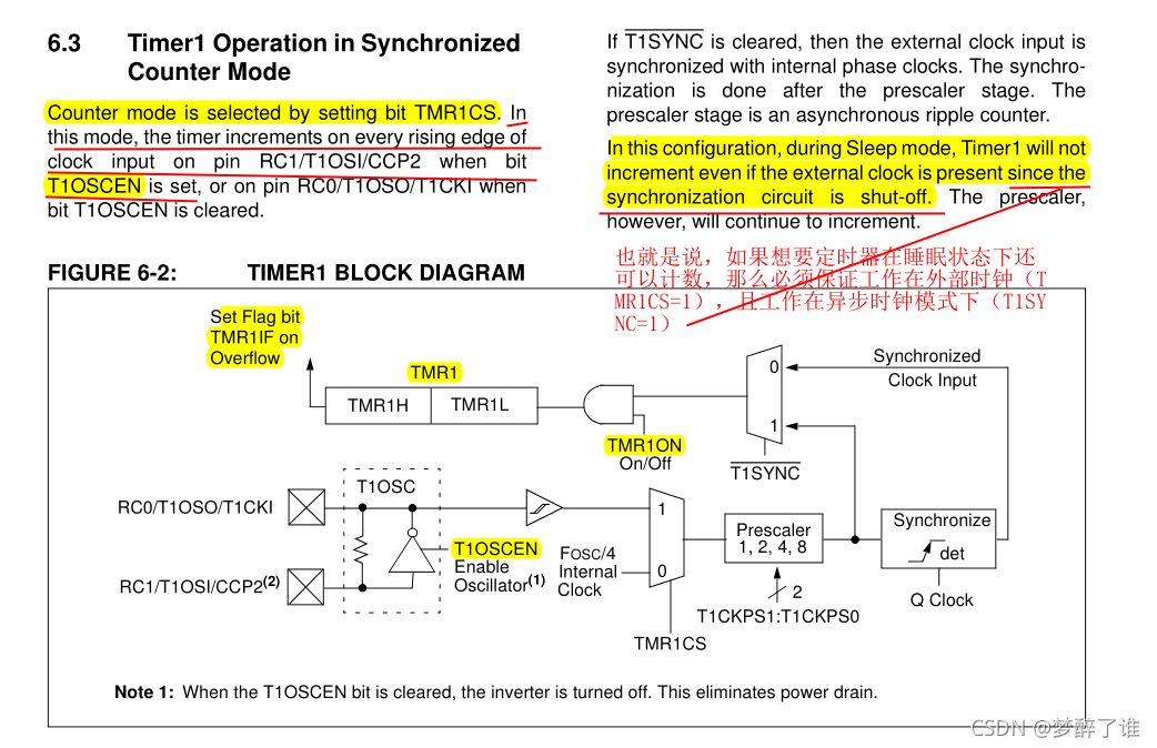
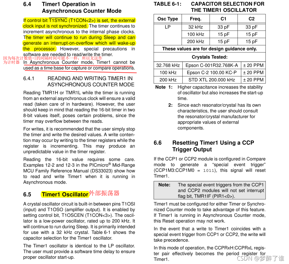
上图中,如果RC0左边外接了外部的晶振,那么T1OSCEN必须置一。这个外部的晶振频率一般都比较低。因为晶振频率越低,一般功耗越低。
为什么这里需要外接晶振呢?保证单片机在休眠模式下还可以计数,这一点是51单片机所不具备的。
2 实现代码
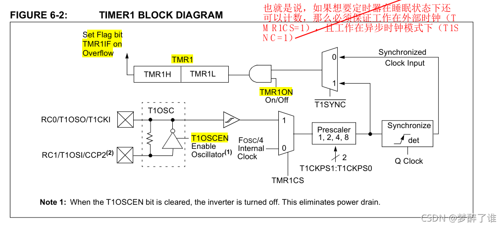
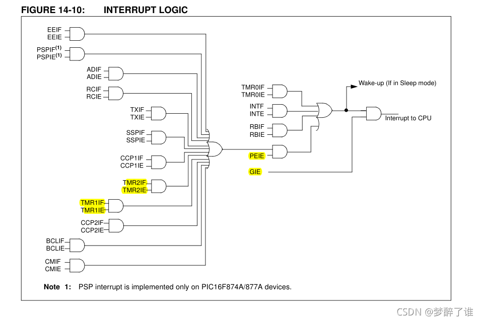
主要根据FIGURE6-2和中断的逻辑框图来编写代码,这样代码的可读性强,也便于理解。但有些寄存器在框图中没有说明,所以也需要仔细阅读定时器0的官方文档,即基本原理部分。
/*----------------函数功能:
中断 定时器1
--------------------------*/
#include<pic.h>// 调用PIC16f87XA单片机的头文件
//#include"delay.h"//调用延时子函数
__CONFIG(0xFF32);//芯片配置字,看门狗关,上电延时开,掉电检测关,低压编程关
//__CONFIG(HS&WDTDIS&LVPDIS);
/*-----------宏定义--------------*/
#define uint unsigned int
#define uchar unsigned char
#define V0 RD0
uint i;
/*-----------子函数声明--------------*/
/*-----------主函数--------------*/
void main()
{
// The corresponding data direction register is TRISA.
// Setting a TRISA bit (= 1) will make the corresponding PORTA pi an input.
// Clearing a TRISA bit (= 0) will make the corresponding PORTA pin an output.
TRISD=0xfe; //设置数据方向 RD7-RD1为输入,RD0为输出
// 1 = Port pin is > VIH,即高电平 ; 0 = Port pin is < VIL,即低电平
PORTD=0X00; //端口赋初值
/********定时器TMR1初始化**********/
// Timer1 can operate in one of two modes: (1)As a Timer ;(2)As a Counter
// The operating mode is determined by the clock select bit, TMR1CS
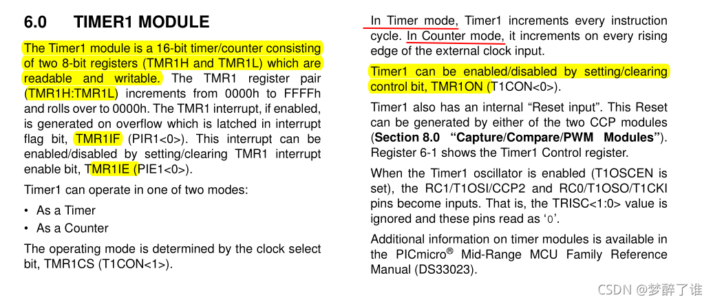
// In Timer mode, Timer1 increments every instruction cycle.
// In Counter mode, it increments on every rising edge of the external clock input
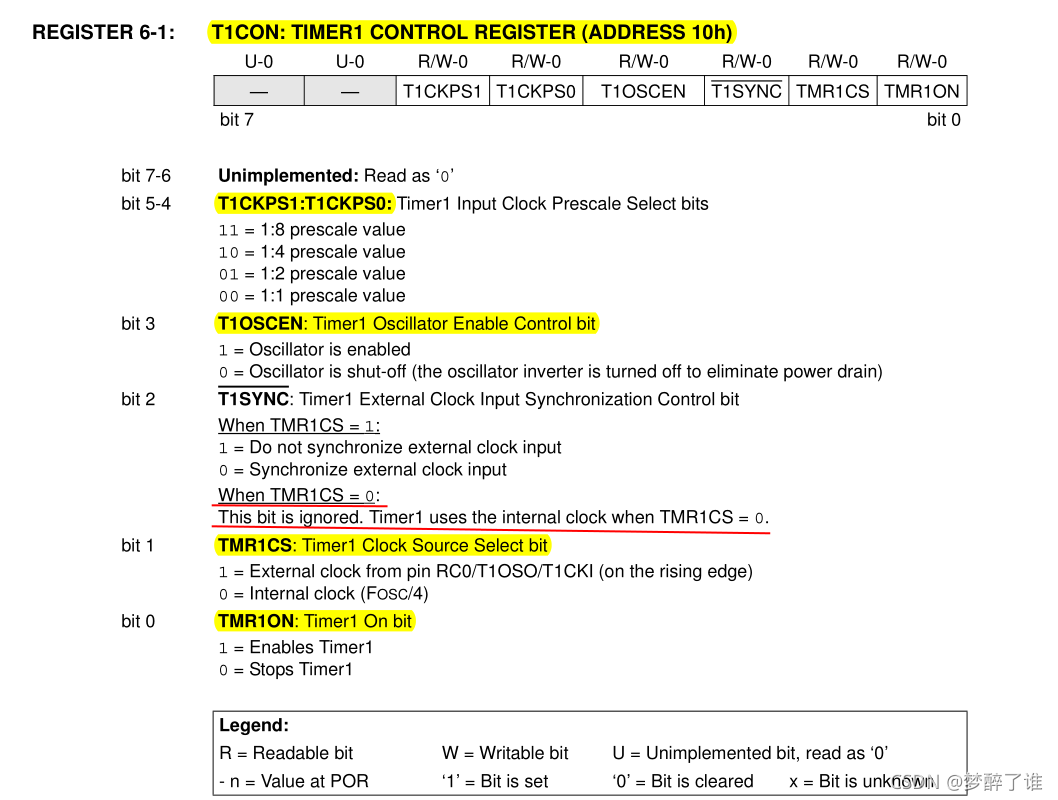
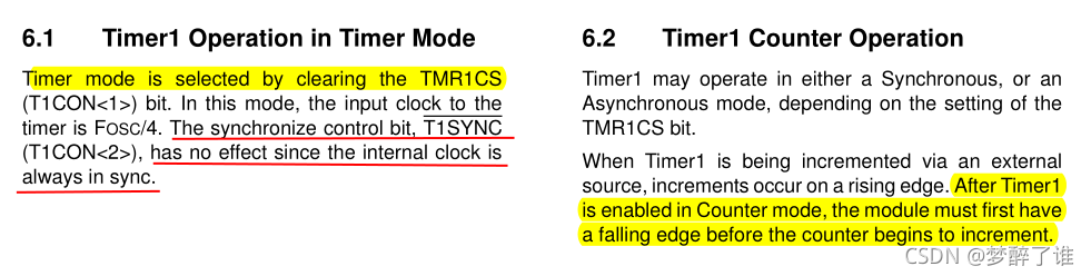
// Counter mode is selected by setting bit TMR1CS. 1 = External clock from pin RC0/T1OSO/T1CKI (on the rising edge)
// Timer mode is selected by clearing the TMR1CS. 0 = Internal clock (FOSC/4)
TMR1CS=0; // TMR1时钟源选择内部指令周期(fosc/4)
// T1CKPS1:T1CKPS0: Timer1 Input Clock Prescale Select bits 预分频器
//预分频 1:1,对应的编码为00
//T1CKPS0=0; // 00 = 1:1 prescale value
//T1CKPS1=0;
//预分频 1:8,对应的编码为11
T1CKPS0=1; // 11 = 1:8 prescale value
T1CKPS1=1;
// Timer1 External Clock Input Synchronization Control bit
// When TMR1CS = 1. 1 = Do not synchronize external clock input. 0 = Synchronize external clock input
// When TMR1CS = 0. This bit is ignored. Timer1 uses the internal clock when TMR1CS = 0.
// The synchronize control bit, T1SYNC. has no effect since the internal clock is always in sync
// T1SYNC=0; // 由于TMR1CS = 0,所以这一位被忽略了
// Timer1 can be enabled/disabled by setting/clearing control bit, TMR1ON
// TMR1ON: Timer1 On bit. 1 = Enables Timer1; 0 = Stops Timer1
TMR1ON=1; //打开计数定时器TMR1,状态为ON
// The Timer1 module is a 16-bit timer/counter consisting of two 8-bit registers (TMR1H and TMR1L)
// which are readable and writable.
//16位计数寄存器给初值,在这里没有考虑中断所造成的时钟延迟13个指令周期
TMR1H=(65536-100)/256; //定时100us*8(八分频),计数寄存器就会溢出
TMR1L=(65536-100)%256;
// The TMR1 interrupt, if enabled,is generated on overflow
// which is latched in interrupt flag bit, TMR1IF
TMR1IF=0; //溢出中断标志位清零
// This interrupt can be enabled/disabled by setting/clearing TMR1 interrupt enable bit, TMR1IE
TMR1IE=1; //溢出中断标志允许位 置一
PEIE=1; //外设中断允许位 置一
//*********开全局中断设置
//定时器T0设置了中断允许,此处要开全局中断
GIE=1; //总中断允许
while(1) // 死循环,单片机初始化后,就一直运行这个死循环
{
}
}
/*************中断服务程序***************/
void interrupt ISR(void)//PIC单片机的所有中断都是这样一个入口
{
// TMR1IF标志位为在计数寄存器由全1变为全0的时候,自动得到置一,即TMR1IF=1.
if(TMR1IF==1) // 需要进一步判断是否为定时器1的溢出中断标志位
{
//定时器中断后,要重置初值,以备下次中断
TMR1H=(65536-100)/256;
TMR1L=(65536-100)%256;
//溢出中断标志位清零 如果TMR1IF出现上升沿,则产生中断,所以中断发生之后要清零。
TMR1IF=0;
// 执行中断处理程序,执行中断产生时想要执行的功能
if(++i>1250) //800us中断一次,再计次1250次后就是1s
{
i=0;
V0=!V0; // 取反 实现一秒的闪烁
}
}
}
为什么有下面两行语句,这是由中断决定的,如下图所示。
	PEIE=1;					//外设中断允许位置一
	GIE=1;					//总中断允许


 1290
1290

 被折叠的 条评论
为什么被折叠?
被折叠的 条评论
为什么被折叠?
 到【灌水乐园】发言


