


【HDLBits】Verification:Reading Simulations_Finding bugs in code
I Mux(Bugs mux2)
1.代码编写
module top_module (
    input sel,
    input [7:0] a,
    input [7:0] b,
    output [7:0]out  );

    assign out = (sel)? a:b;

endmodule
2.提交结果
Success
3.题目分析
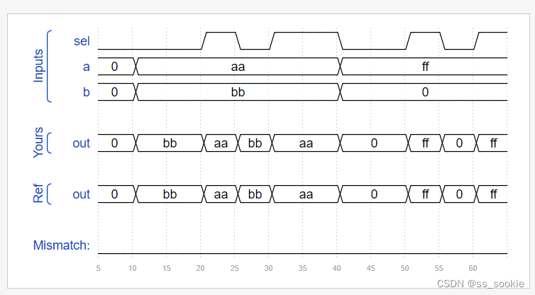
This 8-bit wide 2-to-1 multiplexer doesn’t work. Fix the bug(s).
这题有病,同样的代码试了前两次都是高阻态,incorrect;多试几次又success了。
II NAND (Buges nand3)
1.代码编写
module top_module (input a, input b, input c, output out);//
	wire out2;
    andgate inst1 ( out2,a,b,c,1'b1,1'b1);
    assign out = ~out2;

endmodule
2.提交结果
Success
3.题目分析
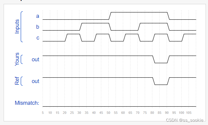
This three-input NAND gate doesn’t work. Fix the bug(s).
You must use the provided 5-input AND gate:
module andgate ( output out, input a, input b, input c, input d, input e );
用5输出与门实现3输入与非门,多余两个端口输入为1,这样才保证不影响与的结果。
从与变与非,取反即可。
III Mux(Bugs mux4)
1.代码编写
module top_module (
    input [1:0] sel,
    input [7:0] a,
    input [7:0] b,
    input [7:0] c,
    input [7:0] d,
    output [7:0] out  ); //

    wire [7:0]mux0, mux1;
    mux2 instance0 ( sel[0],a,b, mux0 );
    mux2 instance1 ( sel[0],c,d, mux1 );
    mux2 instance2 ( sel[1], mux0, mux1,  out );

endmodule
2.提交结果
Success
3.题目分析
This 4-to-1 multiplexer doesn’t work. Fix the bug(s).
You are provided with a bug-free 2-to-1 multiplexer:
module mux2 (
input sel,
input [7:0] a,
input [7:0] b,
output [7:0] out
);
做出电路图:
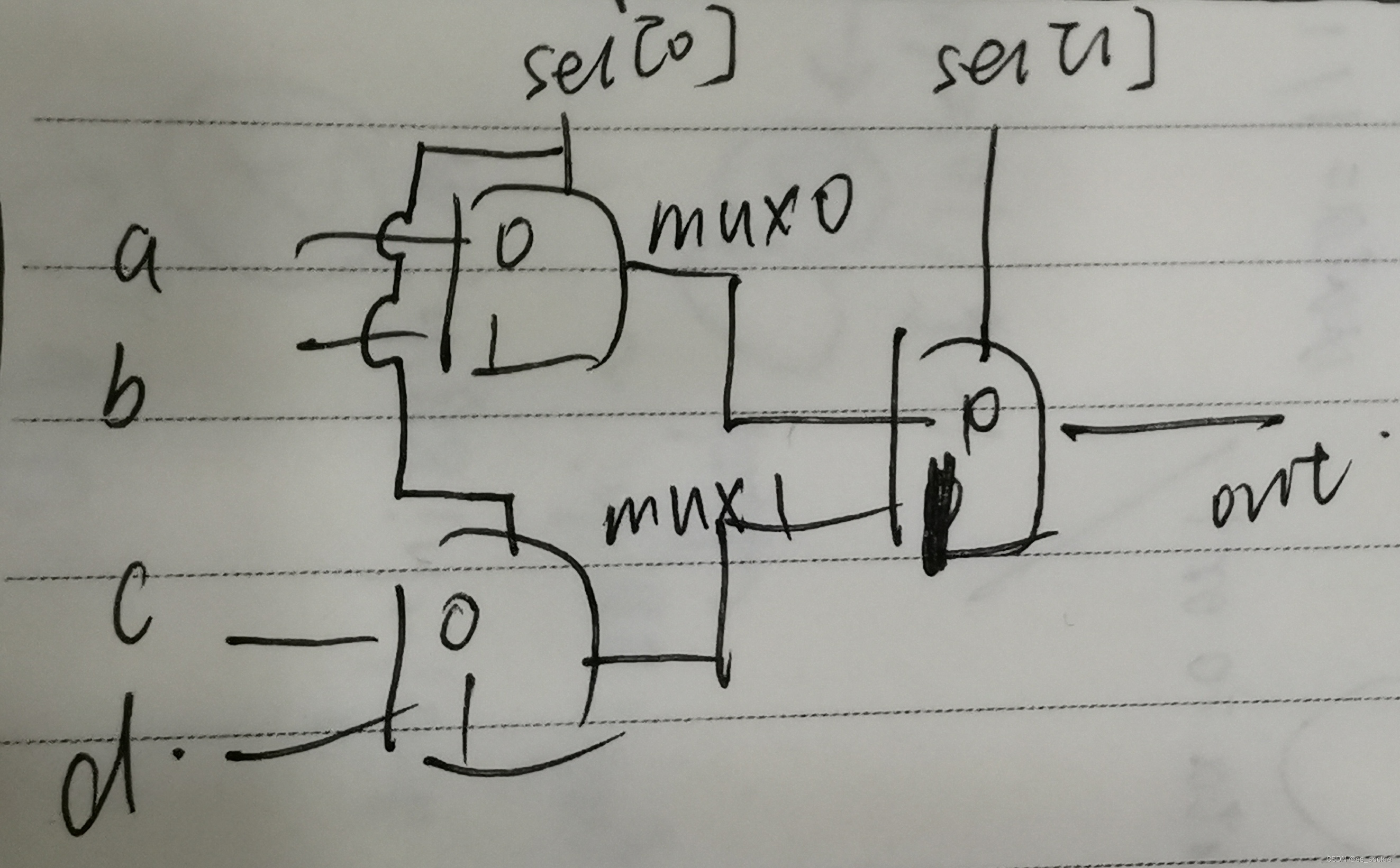
需修改:mux0,mux1的位宽;sel输入的位;例化模块名。
IV Add/sub (Bugs addsubz)
1.代码编写
// synthesis verilog_input_version verilog_2001
module top_module (
    input do_sub,
    input [7:0] a,
    input [7:0] b,
    output reg [7:0] out,
    output reg result_is_zero
);//

    always @(*) begin
        case (do_sub)
          0: out = a+b;
          1: out = a-b;
        endcase

        if (out == 8'd0) //~x
            result_is_zero = 1;
        else
            result_is_zero = 0;
    end

endmodule
2.提交结果
Success
3.题目分析
The following adder-subtractor with zero flag doesn’t work. Fix the bug(s).
改动:if(~ x) -> if(state==8’d0),~ x不是boolean变量。
加条件else,否则形成类似锁存器的结构,result_is_zero始终保持1。
V Bugs case (Bugs case)
1.代码编写
module top_module (
    input [7:0] code,
    output reg [3:0] out,
    output reg valid=1 );//

    always @(*) begin
         valid = 1;
        case (code)
            8'h45: out = 0;
            8'h16: out = 1;
            8'h1e: out = 2;
            8'h26: out = 3;
            8'h25: out = 4;
            8'h2e: out = 5;
            8'h36: out = 6;
            8'h3d: out = 7;
            8'h3e: out = 8;
            8'h46: out = 9;
            default: begin out = 0;valid = 0;end
        endcase
    end

endmodule
2.提交结果
Success
3.题目分析
This combinational circuit is supposed to recognize 8-bit keyboard scancodes for keys 0 through 9. It should indicate whether one of the 10 cases were recognized (valid), and if so, which key was detected. Fix the bug(s).
修改:进制错误、default缺失out,其他情况缺失valid。


 102
102


 被折叠的 条评论
为什么被折叠?
被折叠的 条评论
为什么被折叠?
 到【灌水乐园】发言


