


3.Circuits
3.1Combinational Logic
3.1.1Basic Gates
3.1.1.1 Wire
问题陈述:
实现以下电路:

Verilog代码:
module top_module (
    input in,
    output out);
    assign out=in;
endmodule
3.1.1.2 GND
问题陈述:
实现以下电路:

Verilog代码:
module top_module (
    output out);
	assign out=1'b0;
endmodule
3.1.1.3 NOR
问题陈述:
实现以下电路:

Verilog代码:
module top_module (
    input in1,
    input in2,
    output out);
    assign out=~(in1|in2);
endmodule
3.1.1.4 Another gate
问题陈述:
实现以下电路:

Verilog代码:
module top_module (
    input in1,
    input in2,
    output out);
assign out=in1&~in2;
endmodule
3.1.1.5 Two gate
问题陈述:
实现以下电路:

Verilog代码:
module top_module (
    input in1,
    input in2,
    input in3,
    output out);
    assign out=in3^~(in1^in2);
endmodule
3.1.1.6 More logic gate
问题陈述:
构建具有两个输入a和b的组合电路。
有 7 个输出,每个都有一个逻辑门驱动它:
out_and: a and b
out_or: a or b
out_xor: a xor b
out_nand: a nand b
out_nor: a nor b
out_xnor: a xnor b
out_anotb: a and-not b
Verilog代码:
module top_module(
    input a, b,
    output out_and,
    output out_or,
    output out_xor,
    output out_nand,
    output out_nor,
    output out_xnor,
    output out_anotb
);
    assign out_and=a&b;
    assign out_or=a|b;
    assign out_xor=a^b;
    assign out_nand=~(a&b);
    assign out_nor=~(a|b);
    assign out_xnor=~(a^b);
    assign out_anotb=a&~b;
endmodule
3.1.1.7 7420chip
问题陈述:
创建一个与 7420 芯片功能相同的模块。它有 8 个输入和 2 个输出。
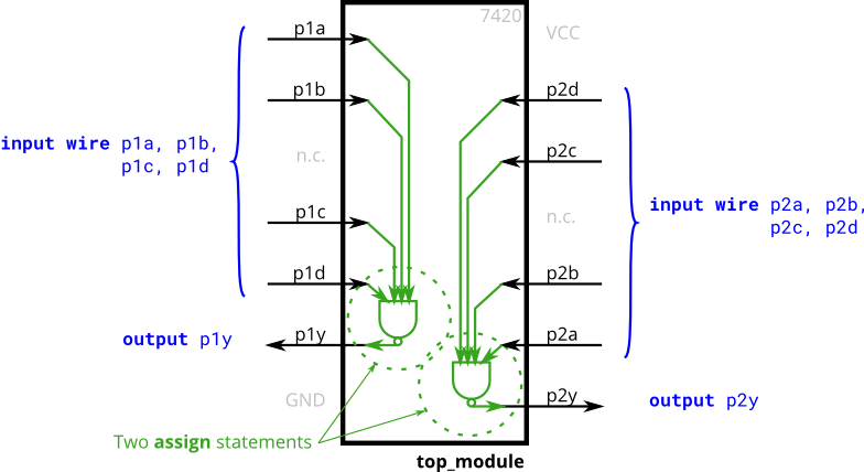
Verilog代码:
module top_module (
    input p1a, p1b, p1c, p1d,
    output p1y,
    input p2a, p2b, p2c, p2d,
    output p2y );
    assign p1y=~(p1a&p1b&p1c&p1d);
    assign p2y=~(p2a&p2b&p2c&p2d);
endmodule
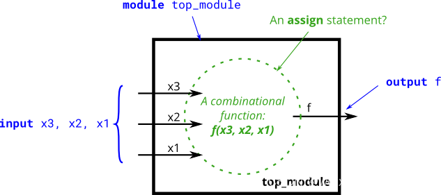
3.1.1.8 Truth tables
问题陈述:
创建一个实现上述真值表的组合电路。
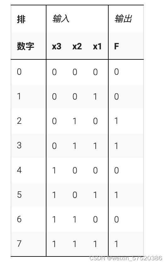
分析:
Verilog代码:
module top_module(
    input x3,
    input x2,
    input x1,  // three inputs
    output f   // one output
);
    assign f=(x2&~x3)||(x3&x1);

endmodule


 3302
3302


 被折叠的 条评论
为什么被折叠?
被折叠的 条评论
为什么被折叠?
 到【灌水乐园】发言


