


GPIO
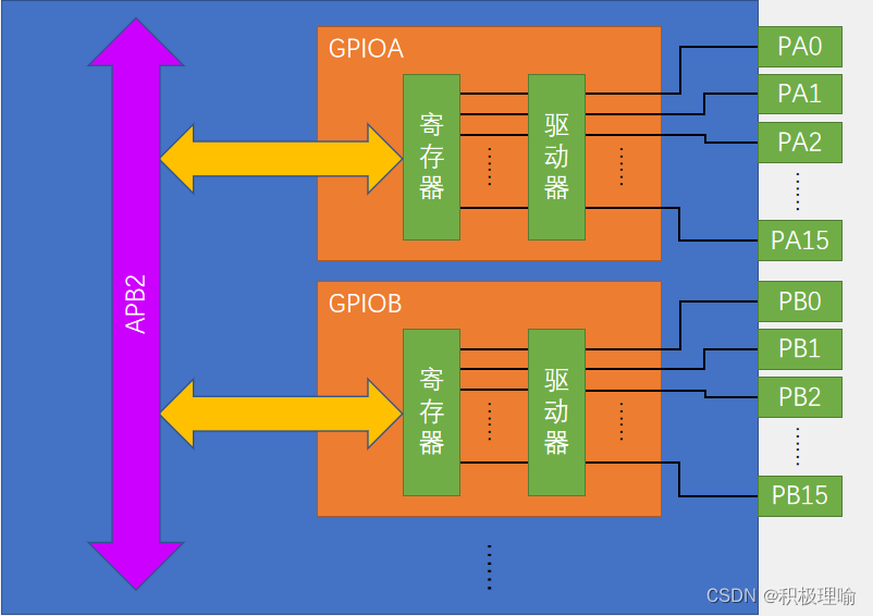
在STM32中,所有GPIO都挂载在APB2外设总线上,每个GPIO有16引脚,编号从0-15。
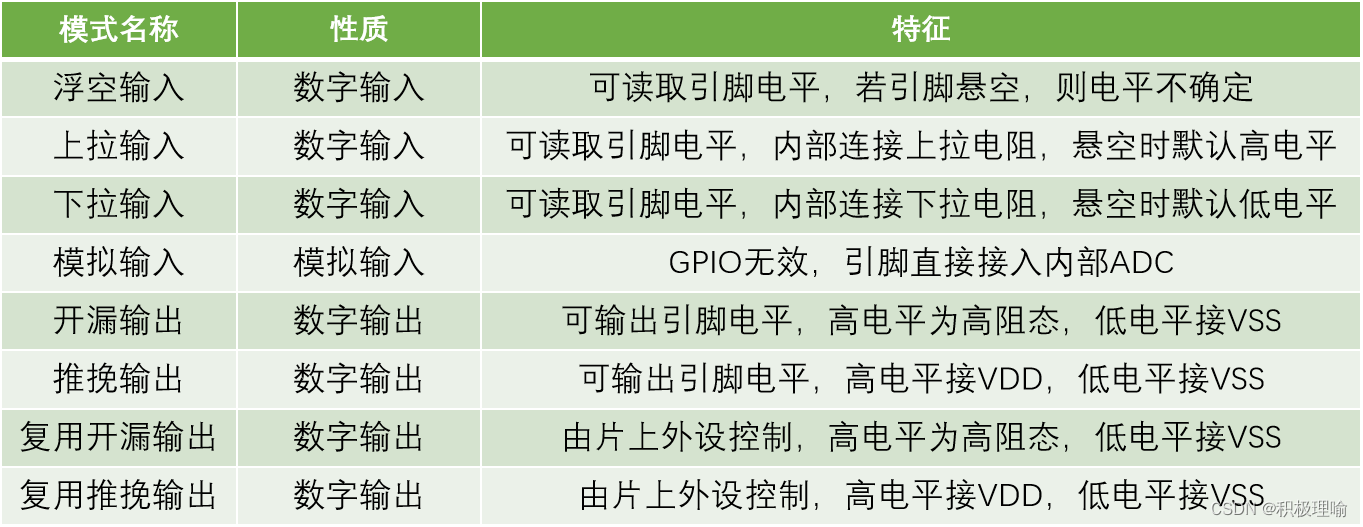
通过配置GPIO端口配置寄存器 ,端口可以配成以下八种模式。
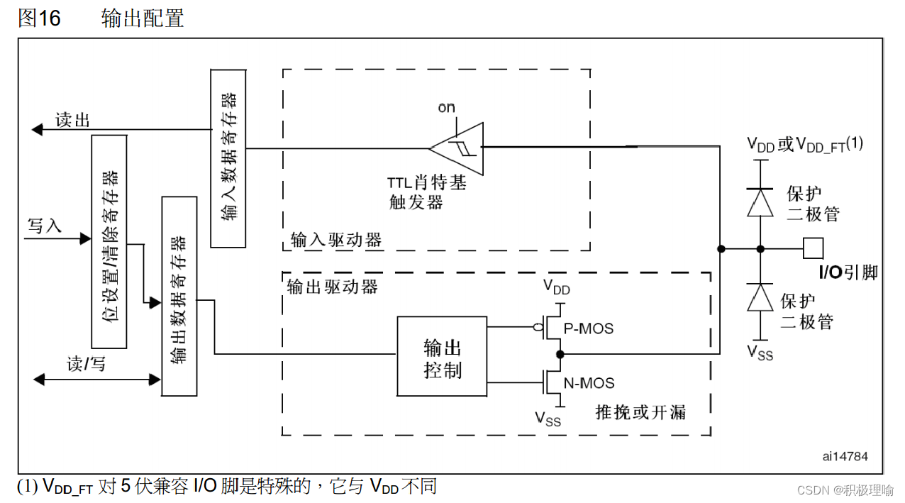
下面介绍两种输出模式:
推挽输出
推挽模式下,P-MOS和N-MOS均有效。输出数据寄存器输出1时,VDD导通,IO后输出高电平。输出数据寄存器输出0时,VSS导通,IO后输出低电平。所以推挽模式下,高低电平驱动均有效。
开漏输出
开漏输出模式下,N-MOS管有效。输出数据寄存器输出0时,VSS导通,IO后输出低电平。所以开漏输出模式下,低电平驱动有效。
点亮A0口LED
#include "stm32f10x.h"                  // Device header
#include "Delay.h"

int main(void)
{
	RCC_APB2PeriphClockCmd(RCC_APB2Periph_GPIOA,ENABLE);	//开启时钟

	GPIO_InitTypeDef GPIO_InitStruct;
	GPIO_InitStruct.GPIO_Mode=GPIO_Mode_Out_OD;	//开漏输出
	GPIO_InitStruct.GPIO_Pin=GPIO_Pin_0;
	GPIO_InitStruct.GPIO_Speed= GPIO_Speed_50MHz;
	GPIO_Init(GPIOA,&GPIO_InitStruct);

	while(1)
	{
		GPIO_ResetBits(GPIOA,GPIO_Pin_0);
		Delay_ms(500);
		GPIO_SetBits(GPIOA,GPIO_Pin_0);
		Delay_ms(500);
	}
}
GPIO_Mode_Out_OD 开漏输出模
GPIO_Mode_Out_PP 推挽输出模式
GPIO_ResetBits 置IO低电平
GPIO_SetBits 置IO高电平
LED流水灯
LED长脚是正极,短脚是负极。这里采用的是推挽模式下低电平驱动。
for循环点亮
#include "stm32f10x.h"                  // Device header
#include "Delay.h"

int main(void)
{
	RCC_APB2PeriphClockCmd(RCC_APB2Periph_GPIOA,ENABLE);	//开启GPIOA时钟

	GPIO_InitTypeDef GPIO_InitStruct;
	GPIO_InitStruct.GPIO_Mode=GPIO_Mode_Out_PP;
	GPIO_InitStruct.GPIO_Pin=GPIO_Pin_All;
	GPIO_InitStruct.GPIO_Speed= GPIO_Speed_50MHz;
	GPIO_Init(GPIOA,&GPIO_InitStruct);

	while(1)
	{
		unsigned char i;
		for(i=0;i<8;i++)
		{
			GPIO_Write(GPIOA,~(0x0001<<i));
			Delay_ms(500);
		}

	}
}
数组点亮:
#include "stm32f10x.h"                  // Device header
#include "Delay.h"

int main(void)
{
	RCC_APB2PeriphClockCmd(RCC_APB2Periph_GPIOA,ENABLE);	//开启GPIOA时钟

	GPIO_InitTypeDef GPIO_InitStruct;
	GPIO_InitStruct.GPIO_Mode=GPIO_Mode_Out_PP;		//推挽模式
	GPIO_InitStruct.GPIO_Pin=GPIO_Pin_All;			//GPIOA所有位口
	GPIO_InitStruct.GPIO_Speed= GPIO_Speed_50MHz;
	GPIO_Init(GPIOA,&GPIO_InitStruct);

	while(1)
	{
		unsigned char i;
		int Num[]={0x0080,0x0040,0x0020,0x0010,0x0008,0x0004,0x0002,0x0001};
		for(i=0;i<8;i++)
		{
			GPIO_Write(GPIOA,~Num[i]);
			Delay_ms(500);
		}

	}
}
蜂鸣器报警
这里是用GPIOB12口来连接蜂鸣器。蜂鸣器低电平驱动。
#include "stm32f10x.h"                  // Device header
#include "Delay.h"

int main(void)
{
	RCC_APB2PeriphClockCmd(RCC_APB2Periph_GPIOB,ENABLE);	//开启GPIOB时钟

	GPIO_InitTypeDef GPIO_InitStruct;
	GPIO_InitStruct.GPIO_Mode=GPIO_Mode_Out_PP;
	GPIO_InitStruct.GPIO_Pin=GPIO_Pin_12;
	GPIO_InitStruct.GPIO_Speed= GPIO_Speed_50MHz;
	GPIO_Init(GPIOB,&GPIO_InitStruct);

	while(1)
	{
		GPIO_ResetBits(GPIOB,GPIO_Pin_12);
		Delay_ms(100);
		GPIO_SetBits(GPIOB,GPIO_Pin_12);
		Delay_ms(100);
		GPIO_ResetBits(GPIOB,GPIO_Pin_12);
		Delay_ms(700);
		GPIO_SetBits(GPIOB,GPIO_Pin_12);
		Delay_ms(700);
	}
}


 3282
3282


 被折叠的 条评论
为什么被折叠?
被折叠的 条评论
为什么被折叠?
 到【灌水乐园】发言


