


电流限制的概念似乎相当直接:当你增加直流/直流转换器的输出电流时,在某个点上不可能再进一步增加。这个水平就是电流限制,这自然导致了一个想法,即电流在某个特定的峰值或最大水平上受到限制。有了这个概念,谷值电流限制的概念可能看起来相当违反直觉。为了更好地理解它,让我们首先看一下峰值电流限制。
峰值电流限制
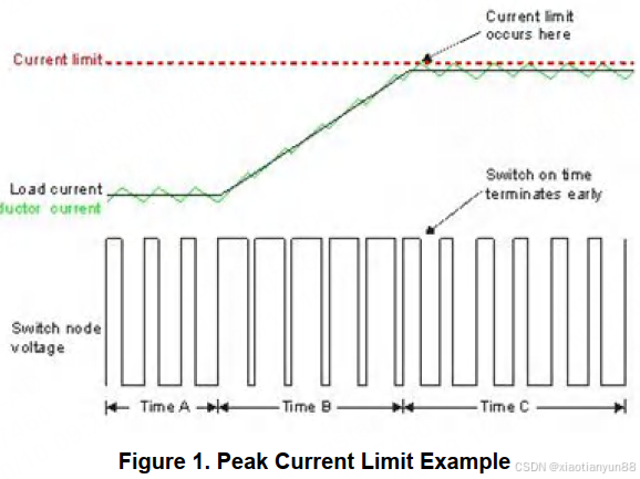
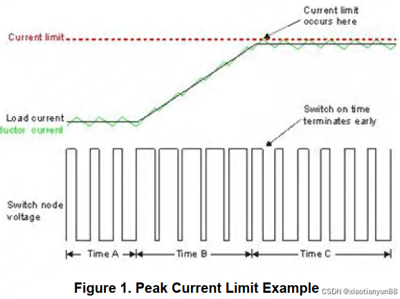
图1显示了峰值电流限制的开关节点电压、负载电流和电感器电流波形。
对于直流/直流降压变换器,输出电流由两部分组成:直流负载电流和交流纹波分量。直流分量是传递给负载的电流,而交流电流则通过输出电容被滤除。
直流分量仅为Vout/Rload。方程1将交流分量表示为电感器的峰对峰电流:

其中Vin是输入电压,Vout是输出电压,Lout是输出电感,Fsw是转换器开关频率。
在转换器导通时间内,开关或电感电流上升到Iout + ILp-p/2。在关断时间内,电流下降到Iout – Ilp-p/2,输出电流是平均电流。对于峰值电流限制,在导通时间内将开关电流与电流限制值进行比较。
在图1所示的波形中,
时间A期间,转换器以固定的恒定负载电流进行调节。
时间B期间,负载电流向电流限制设定点上升。转换器通过增加占空比在每个连续的开关周期中增加输出电流。
时间C期间,转换器在电流限制下运行。当电流达到限制时,导通时间提前终止,关断时间开始。
在关断时间内,电流下降到限制以下。
在下一个开关周期开始时,电流再次开始上升。如果在这个周期内达到电流限制,导通时间再次提前终止。这种类型的电流限制是逐周期峰值电流限制。
降压变换器的开关电流对于谷值电流限制和峰值电流限制是相同的。
谷值电流限制
图2展示了谷值电流限制时开关节点电压、负载电流和电感电流波形。

与其在导通时间内监控电流,不如在关断时间内监控电流。如前所述,电流在关断时间内减少。在开关周期结束时,将开关电流与谷值电流限制值进行比较。
在图2所示的波形中,
时间A期间,转换器以固定的恒定负载电流进行调节。
时间B期间,负载电流向电流限制设定点上升。由于这是一个恒定导通时间的例子,转换器通过减少关断时间来增加每个连续开关周期的输出电流,从而增加占空比。
时间C期间,转换器以电流限制运行。当电流高于限制时,关断时间延长,直到开关电流等于谷值电流限制;然后允许开始下一个开关周期。
从根本上说,峰值电流限制和谷值电流限制都是通过相对于导通时间增加关断时间来操作的。
在峰值电流限制的情况下,导通时间减少,关断时间增加相同的量,保持设定的开关频率。
谷值电流限制保持导通时间不变,只增加关断时间,因此在电流限制操作期间开关频率降低。
优点和缺点
现在您已经了解了基本的工作原理,很容易看出每种电流限制何时适用。使用峰值电流模式控制的转换器通常会使用峰值电流限制。对于峰值电流模式控制,开关电流波形本质上是脉冲宽度调制(PWM)斜坡波形。导通时间内的上升电流与一个与误差放大器输出成比例的水平进行比较,该水平对应于所需的负载电流。当开关电流达到该水平时,导通时间终止。
用于设置占空比的相同电路也可以通过允许控制电压的上限钳位来检测电流限制。峰值电流限制有一些缺点。主要缺点涉及“消隐时间”。在导通时间开始时,开关节点波形具有非常快的上升时间。可能存在相当大的超调、过冲和振荡。在此期间,不可能准确监控电流,因此通常指定一个最小导通时间或消隐时间。在此期间,电流不受监控,可能超过限制。
您可以看到,谷值电流限制保持导通时间恒定,同时延长关断时间以将电流降至限制以下,因此很自然地会想到在使用恒定导通时间控制模式的转换器中使用这种类型的电流限制。恒定导通时间控制将导通时间设置为固定值,并使用滞回比较器在反馈部分的输出电压低于预设水平时结束关断时间。如果电流高于限制,谷值电流限制将覆盖此控制信号,增加关断时间。
这是谷值电流限制相对于峰值电流的一个优势。谷值电流限制在关断时间结束之前、在任何开关过渡之前应用。不需要任何消隐时间。
另一个考虑因素是传感电路的物理位置。对于电流限制,实际电流有时可能无法直接感测。相反,可以监控与电流成比例的电压。这个电压可以直接从相应的开关获得,或者更典型地从较小的镜像元件获得。对于电流模式控制,这个传感元件位于高压侧开关,并相对于输入电压轨进行感测。输入电压可能会在一个很大的范围内变化,并且有显著的纹波。另一方面,谷值电流限制感测低压侧开关电流。传感元件参照相对更为安静且恒定的电路地。虽然这是一个优势,但它也有一个显著的局限性。由于谷值电流限制感测低压侧开关的电流,它通常仅限于同步转换器。
谷值电流限制并没有什么神秘之处。它和其他类型的电流限制一样有效。转换器使用的控制模式主要决定了电流限制的类型。
Understanding Valley Current Limit
JohnTucker
The concept of current limit seems pretty straightforward: when you increase the output current of a DC/DC converter, at a certain point it’s not possible to increase it any further. This level is the current limit, which naturally leads to the idea that the current is limited at some particular peak or maximum level.
With this in mind, the concept of valley current limit can seem quite counterintuitive. To better understand it, let’s first take a look at peak current limit.
Peak Current Limit
Figure 1 shows the switch-node voltage, load current and inductor current waveforms for peak current limit.
For a DC/DC buck converter, the output current consists of two parts: the DC load current and an AC ripple component. The DC component is the current delivered to the load, while the AC current is filtered out by the output capacitance.
The DC component is just Vout/Rload. Equation 1 expresses the AC component as the peak-to-peak inductor current:

where Vin is the input voltage, Vout is the output voltage, Lout is the output inductor and Fsw is the converter switching frequency.
During the converter on-time, the switch or inductor current rises to Iout + ILp-p/2. During the off-time, the current decreases to Iout – Ilp-p/2 and the output current is the average current. For peak current limit, the switch current is compared to the current limit value during the on-time.
In the waveforms shown in Figure 1, during Time A, the convert is regulating at a fixed-constant load current.
During Time B, the load current ramps up toward the current limit set point. The converter increases the output current in each successive switching cycle by increasing the duty cycle. During Time C, the converter is operating at the current limit.
When the current reaches the limit, the on-time terminates early and the off-time begins. During the off-time the current decreases back below the limit. At the start of the next switching cycle, the current starts to ramp up again. If it reaches the current limit during this cycle, the on-time once again terminates early. This type of current limit is a cycle-by-cycle peak current limit.The switching current of the buck converter is the same for valley current limit as it is for peak current limit.
Valley Current Limit
Figure 2 shows the switch-node voltage, load current and inductor current waveforms for valley current limit.
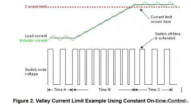
Instead of monitoring the current during the on-time, the current is monitored during the off-time. As noted, the current decreases during the off-time. At the end of the switching cycle, the switch current is compared to the valley current limit value.
In the waveforms shown in Figure 2 during Time A, the converter is regulating at a fixed-constant load current.
During Time B, the load current ramps up toward the current limit set point. Since this is a constant on-time example, the converter increases the output current in each successive switching cycle by decreasing the off-time to increase the duty cycle. During Time C, the converter is operating at the current limit. When the current is above the limit, the off-time is extended until the switch current equals the valley current limit; then the next switching cycle is allowed to start.
Fundamentally, both peak current limit and valley current limit operate by increasing the off-time relative to the on-time. In the case of peak current limit, the on-time decreases and the off-time increases by the same amount, maintaining the set switching frequency. Valley current limit keeps the on-time constant while only increasing the off-time so that the switching frequency decreases during current limit operation.
Advantages and Disadvantages
Now that you understand the basic operating principles, it is easy to see when each type of current limit may be appropriate. Converters using peak current mode control will typically use peak current limit. For peak current- mode control, the switch current waveform is essentially the pulse-width modulation (PWM) ramp waveform. The rising current during the on-time is compared to a level proportional to the output of the error amplifier that corresponds to the required load current. When the switch current reaches that level, the on-time terminates.
The same circuitry used to set the duty cycle can also detect the current limit by allowing an upper clamp of the control voltage. There are some disadvantages to peak current limit. The main disadvantage concerns “blanking time.” At the start of the on-time, the switch-node waveform has a very fast rise time.
There may be considerable overshoot and ringing present. During this time, it is not possible to monitor the current accurately, so there is typically a minimum on-time or blanking time specified. During this time, the current is not monitored and may exceed the limit.


 254
254

 被折叠的 条评论
为什么被折叠?
被折叠的 条评论
为什么被折叠?
 到【灌水乐园】发言


