


EXAMPLE NAME:
BUCK_PCC_FIX_FQ_EXAMPLE_XMC42
OVERVIEW:
This example implements a Buck Converter in Peak Current Control mode with the
BUCK_PCC_FIX_FQ APP for being used together with the XMC Digital Power Explorer kit.
DESCRIPTION:
This example implements a Buck Converter in Peak Current Control mode for being used together with the XMC Digital Power Explorer kit. Visit www.infineon.com/xmc_dp_exp. The project is implemented using XMC4200
digital power control card, housing a 32-bit ARM Cortex M4 based microcontroller with Floating Point Unit. In addition, it also has dedicated control peripherals such as the HRPWM module, including CSG module. CSG is comprised of an analog comparator and an intelligent DAC capable of creating negative ramps for best slope compensation. HRPWM peripheral in XMC4200 also provides the ability to generate high resolution PWM (150 ps resolution). A Versatile Analog-to-Digital (VADC) module for analog signal measurement, is also included making XMC4200 suitable for applications that require fast calculation such as the Peak Current Control mode.
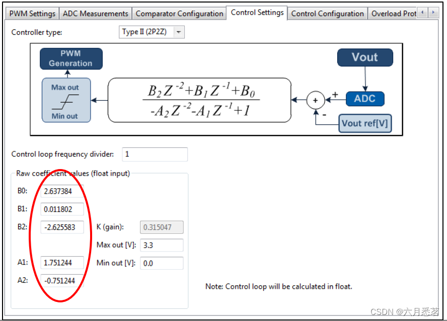
The current Control loop is implemented by a classic 2 poles 2 zeros filter using floating point values.
The provided filter coefficients have been selected to have the following controller characteristics:
- Switching freq = 200kHz
- Crossover freq = 10kHz
- Phase margin = 50 degrees
- PWM = 80MHz
- ADC resolution = 12 bits
VADC conversion is being continuously triggered by the Compare Match 2 of the CCU8 (set by default to the maximum, period value).
Once the output voltage has being measured by the VADC, an interrupt is generated.
Inside the ISR, the 2 poles 2 zeros controller is applied and new value for the DAC slope start is set.

Note: The example BUCK_PCC_DIGITAL_POWER_EXPLORER_XMC42, also available in DAVE server, implements similar functionality for the same hardware (XMC Digital Power Explorer Kit). The main difference is that in the BUCK_PCC_DIGITAL_POWER_EXPLORER_XMC42 project low level APPs are being used for configuring individually the required peripherals. Compared to using the BUCK_PCC_FIX_FQ APPs, the low level APPs approach has advantages like the flexibility or the higher performance for the control loop and disadvantages like the higher complexity in terms of configuration and readability of the code.
REQUIRMENTS:
- XMC4200 Digital Power Control Card and XMC Digital Power Explorer Kit
- DAVE Version: 4.2.8
HOW TO CREATE THE PROJECT:
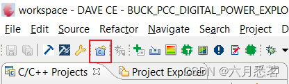
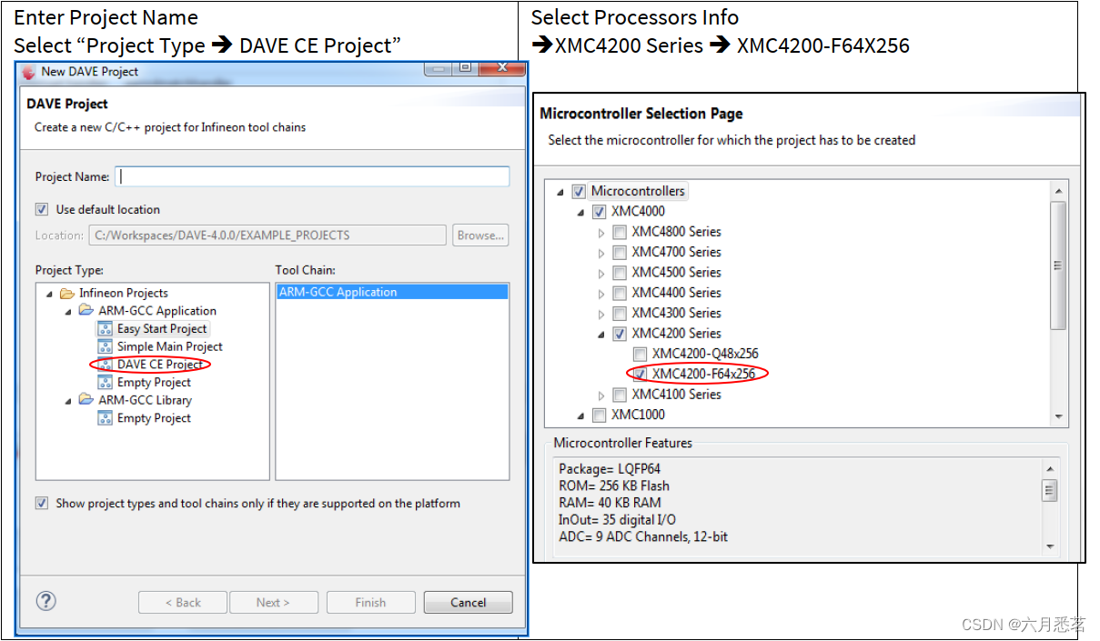
1. Open the DAVE CE and use “Add IDE New Project Wizard” on the toolbar to add a new DAVE Project.
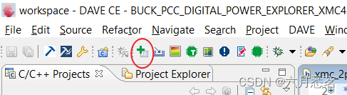
2. Use the “Add New App” in the toolbar to add 1 instance of BUCK_PCC_FIX_FQ. Configure the APP instance with the following configurations.
Views: APP Dependency Tree and APP Dependency
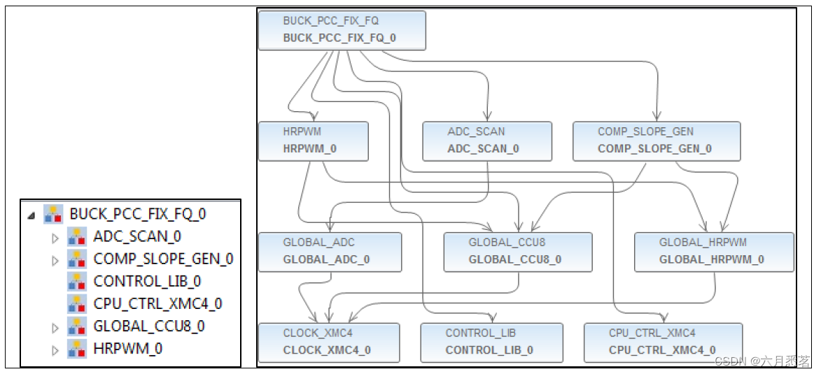
BUCK_PCC_FIX_FQ_XMC42:
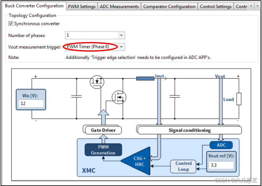
- Buck Converter Configuration tab :
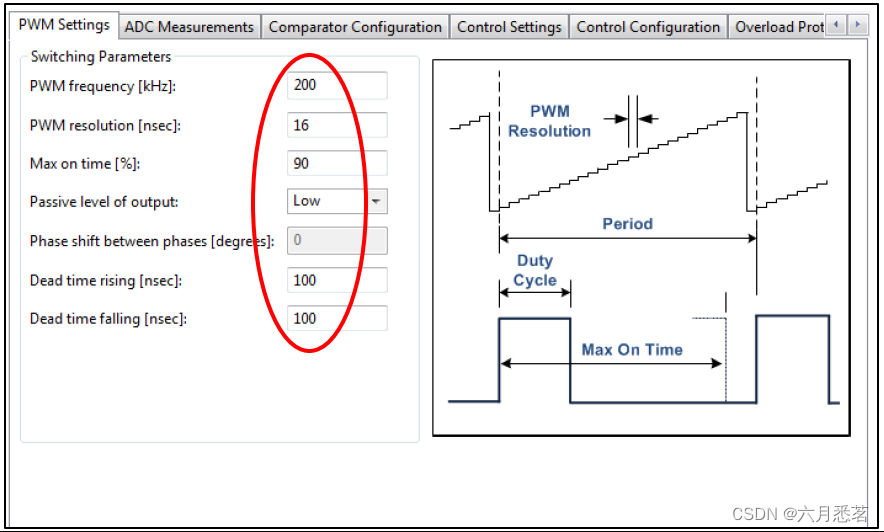
- PWM Settings tab :
- Control Settings tab :
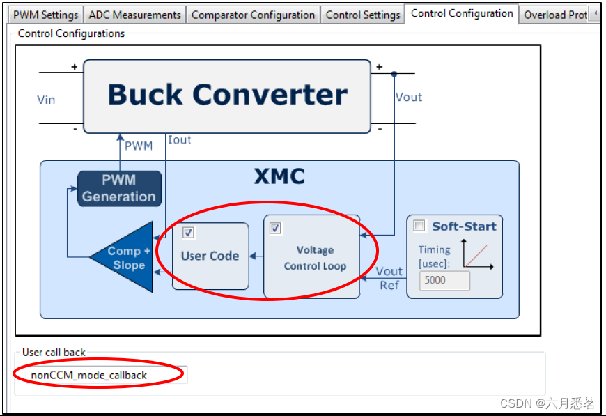
- Control Configuration tab :
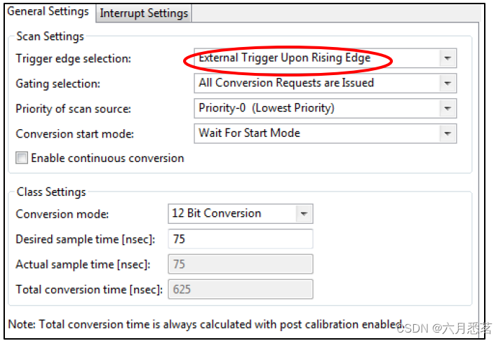
ADC_SCAN :
- General Settings tab :
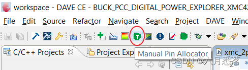
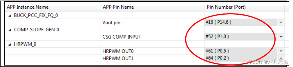
3. Use the “Manual Pin Allocator” found in the toolbar, configure the pins for the VADC, CSG and PWM outputs.
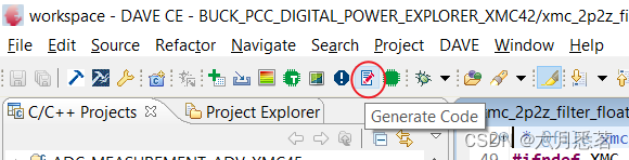
4. Generate the code for the configurations made and change main.c accordingly.
/*******************************************************************************
 Copyright (c) 2016, Infineon Technologies AG                                 **
 All rights reserved.                                                         **
                                                                              **
                                                                              **
********************************************************************************
**                                                                            **
**                                                                            **
** PLATFORM : Infineon XMC4200 Series                                         **
**                                                                            **
** AUTHOR : Application Engineering Team                                      **
**                                                                            **
** version 1.0.0  Initial version                                             **
**                                                                            **
** MODIFICATION DATE : May, 23, 2016                                          **
**                                                                            **
*******************************************************************************/


#include <DAVE.h>                 //Declarations from DAVE Code Generation (includes SFR declaration)

/**

 * @brief main() - Application entry point
 *
 * <b>Details of function</b><br>
 * This routine is the application entry point. It is invoked by the device startup code. It is responsible for
 * invoking the APP initialization dispatcher routine - DAVE_Init() and hosting the place-holder for user application
 * code.
 */

int main(void)
{
  DAVE_STATUS_t status;

  status = DAVE_Init();           /* Initialization of DAVE APPs  */

  if(status == DAVE_STATUS_FAILURE)
  {
    /* Placeholder for error handler code. The while loop below can be replaced with an user error handler. */
    XMC_DEBUG("DAVE APPs initialization failed\n");

    while(1U)
    {

    }
  }

  BUCK_PCC_FIX_FQ_Start(&BUCK_PCC_FIX_FQ_0);

  /* Placeholder for user application code. The while loop below can be replaced with user application code. */
  while(1U)
  {

  }
}

/* In order to avoid non-CCM mode, low side switch of synchronous buck
  * is switched off when current demand is low enough
  * The low side switch off is achieve in this case by using dead time modulation*/
void nonCCM_mode_callback(BUCK_PCC_FIX_FQ_t * const handle_ptr)
{

	if(BUCK_PCC_FIX_FQ_0.typeII->out < 300U)
	{
	     XMC_HRPWM_HRC_SetDeadTimeFalling(HRPWM_0.hrc_slice_ptr, 500U);
	  }
	  else
	  {
		  XMC_HRPWM_HRC_SetDeadTimeFalling(HRPWM_0.hrc_slice_ptr, 5U);
	  }

	  XMC_HRPWM_EnableHighResolutionShadowTransfer(HRPWM_0.hrc_module_ptr, HRPWM_0.hr_dt_transfer_msk);
}
The generated code:
/* Prepares the timers ready for PWM generation on a external signal event */
BUCK_PCC_FIX_FQ_STATUS_t BUCK_PCC_FIX_FQ_Start(BUCK_PCC_FIX_FQ_t *handle_ptr)
{
  BUCK_PCC_FIX_FQ_STATUS_t status = BUCK_PCC_FIX_FQ_STATUS_SUCCESS;

  XMC_ASSERT("BUCK_PCC_FIX_FQ_Start: handle_ptr is NULL", (handle_ptr != NULL));

  if ((handle_ptr->state == BUCK_PCC_FIX_FQ_STATE_INITIALIZED) || (handle_ptr->state == BUCK_PCC_FIX_FQ_STATE_STOPPED))
  {
    /* Clears the variables used by the compensator, Starts the BUCK from a known state */
    BUCK_PCC_FIX_FQ_lClearCompensatorVariables(handle_ptr);

    /* Clears the variables used for Over load protection, Starts the BUCK from a known state */
    BUCK_PCC_FIX_FQ_lClearOverloadProtectionVariables(handle_ptr);

#ifdef BUCK_PCC_FIX_FQ_PWM_CCU8_USED /* XMC1x family */
    status = BUCK_PCC_FIX_FQ_lPWM_CCU8_Start(handle_ptr);

#ifdef BUCK_PCC_FIX_FQ_BLANKING_OR_SLOPE_USED
    if (status == BUCK_PCC_FIX_FQ_STATUS_SUCCESS)
    {
      status = BUCK_PCC_FIX_FQ_lPWM_CCU4_Start(handle_ptr);
    }
#endif

#endif

#ifdef BUCK_PCC_FIX_FQ_HRPWM_USED /* XMC4x family */
    if (status == BUCK_PCC_FIX_FQ_STATUS_SUCCESS)
    {
      status = BUCK_PCC_FIX_FQ_lHRPWM_Start(handle_ptr);
    }

    if (status == BUCK_PCC_FIX_FQ_STATUS_SUCCESS)
    {
      status = BUCK_PCC_FIX_FQ_lCOMP_SLOPE_GEN_Start(handle_ptr);
    }
#endif

    if (status == BUCK_PCC_FIX_FQ_STATUS_SUCCESS)
    {

#ifdef BUCK_PCC_FIX_FQ_RESULT_INT_USED
      if ((handle_ptr->config->interrupt_event == BUCK_PCC_FIX_FQ_INTERRUPT_VOUT_RESULT_EVENT))
      {
        NVIC_EnableIRQ((IRQn_Type)handle_ptr->interrupt_config->node); /* Enable Vout Result Event's nvic node */
      }
#endif

#ifdef BUCK_PCC_FIX_FQ_END_OF_REQ_SOURCE_INT_USED
#ifdef BUCK_PCC_FIX_FQ_ADC_SCAN_USED
      if(handle_ptr->adc_config->adc_mode == BUCK_PCC_FIX_FQ_ADC_MODE_SCAN)
      {
        NVIC_EnableIRQ((IRQn_Type)handle_ptr->adc_scan_app_handle_array[0]->rs_intr_handle->node_id); /* Enable end of request source event's nvic node */
      }
#endif

#ifdef BUCK_PCC_FIX_FQ_ADC_QUEUE_USED
      if(handle_ptr->adc_config->adc_mode == BUCK_PCC_FIX_FQ_ADC_MODE_QUEUE)
      {
        NVIC_EnableIRQ((IRQn_Type)handle_ptr->adc_queue_app_handle_array[0]->rs_intr_handle->node_id); /* Enable end of request source event's nvic node */
      }
#endif
#endif

#ifdef BUCK_PCC_FIX_FQ_SOFT_START_USED
      if (handle_ptr->config->soft_start_enable == true)
      {
        status = BUCK_PCC_FIX_FQ_lSYSTIMER_Start(handle_ptr);
      }
#endif

      /* Synchronously start the timers */
      BUCK_PCC_FIX_FQ_lSynchronousStart(handle_ptr);
    }

    handle_ptr->state = BUCK_PCC_FIX_FQ_STATE_RUNNING;
  }
  else
  {
    status = BUCK_PCC_FIX_FQ_STATUS_FAILURE;
  }

  return (status);
}
5. Build and download to the microcontroller.
HOW TO TEST:
- Create the project
- Prepare board set up: connect XMC4200 Digital Power Control Card into XMC Digital Power Explorer and supply power with included power adapter to it. Make sure power on switch is in the “on” position and that the jumper in power board is in the XMC4000 position
- Generate code, compile and flash the application onto the device
- Run the application.
- Check via oscilloscope the different test points available in XMC Digital Power Explorer. Vout is now controlled to be stable at 3,3 V independent of load switching LEDs next to load switches must turn on when that particular load is activated.
- If changes are needed in APPs configuration, make sure code is generated again before compiling


 6475
6475

 被折叠的 条评论
为什么被折叠?
被折叠的 条评论
为什么被折叠?
 到【灌水乐园】发言


