


视频:Zynq Vitis Example with PL Fabric GPIO and BRAM
上一节已经导出了hardware file,Vitis需要使用这个文件。
the hardware file that Vitis needs to take the fabric side and integrate it with the processor side. Last video was very fabric-centered, it was very PL centered and we designed what was going to be in the fabric, and today we're looking at the other side, we're looking at the CPU side and we're going to be designing what's on the CPU. We're going to be writing CU code for the CPU.(Vitis 需要将 Fabric 方面的硬件文件与处理器方面的硬件文件整合在一起。上一个视频以 Fabric ( PL) 为中心,我们设计了 Fabric 中的内容,而今天我们要看的是另一面,我们要看的是 CPU 方面,我们要设计 CPU 上的内容。我们将为 CPU 编写 CU 代码。)
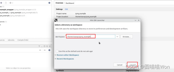
1. 打开Vitis:
Vivado → Tools → Launch Vitis IDE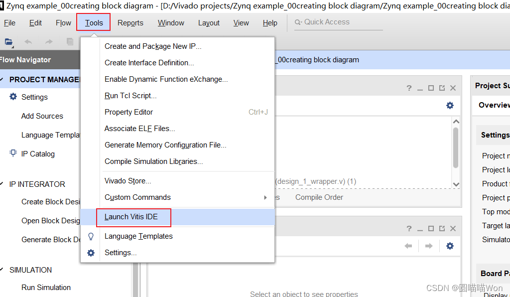
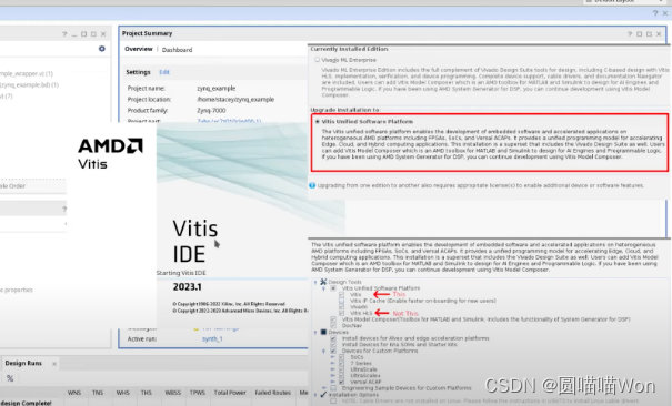
需要注意Vitis和Vitis HLS的区别:
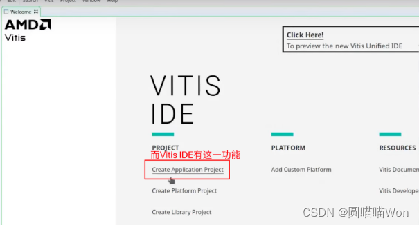
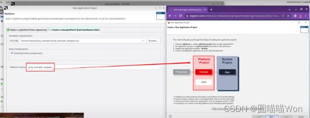
2. 创建application project:
点击“create application project”:
Go create application project so there's a whole stack that we're making here today as you can see in their handy diagram but when we create the application project, it's going to prompt us to make the entire stack. So the application project sits on the whole stack, and then when we make the application project it has to make everything from the top down, so that's what we're going to be going over, but it's going to be quite quick and easy to do because it's a relatively streamlined process. (当我们创建应用程序项目时,它会提示我们去做整个堆栈,所以应用程序项目位于整个堆栈上,然后当我们创建应用程序项目时,它必须从上到下创建所有的东西,但这个过程会很快而且很容易,因为它是一个相对简化的过程。)

选择“从xsa文件创建”:
导入之前从vivado导出的xsa文件。

It's going to create the platform for hardware.(它将为硬件创建平台。)
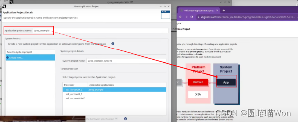
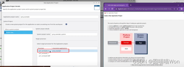
创建“system project”:
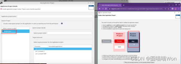
选择domain:standalone。

点击“finish”,完成创建。
3. 创建 Hello World:
It's a lot of different components that you need to kind of bring together but as you can see it's a relatively streamlined process. So even though there were a whole bunch of things in the stack that I was making I only had to supplied with the xsa file and it did everything else for me and all I had to do is basically name my things. So now it's going to create a hello world project.(需要将许多不同的组件组合在一起,但这是一个相对简化的过程。 因此,尽管正在制作的堆栈中有一大堆东西,但我们只需要提供 xsa 文件,它就为我完成了其他所有事情,而我所要做的基本上就是命名我的东西。 接下来要创建一个 hello world 项目。)
Vitis界面和Eclipse比较相似,左上角可以看到代码和这个app的层级架构:

“*.prj”文件很有用,下面介绍一下.prj文件:

点击“navigate to BSP settings”按钮,可以看到它已经选择了我们的两个外设:
我们在fabric中添加了BRAM和GPIO外设,Vivado在xsa文件中告诉Vitis:我们在PL中有这些IP,因此这些驱动程序是可用的。
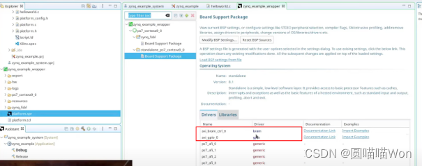
此外,针对这些驱动程序还有一些文档说明和例程。

比如如果想要获取一个例程,可以选择那个例程,如下图,得到了一个获取GPIO IP的例程:

If I have a periphral that I've included in the fabric that I don't know how to use specifically, then I can easily access it and have example code of how to use it.(如果我们在fabric中引用了一个外设,但是我不知道如何具体使用,那么可以通过这种方式很容易地访问它,并获得如何使用它的示例代码。)
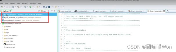
以同样的方式,导入BRAM的例程:

以这两个例程为基础去创建我们自己的工程。
现在我们有3个系统了:
zynq_example_system:hello world
xgpio_example_1_system和xbram_example_1_system:两个例程
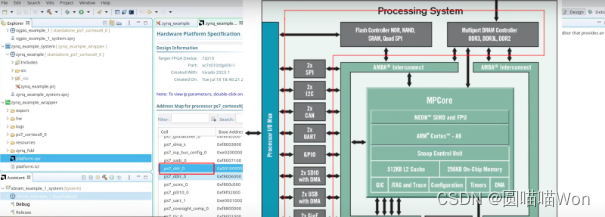
回到.prj文件,点击“HardwareSpecification”:
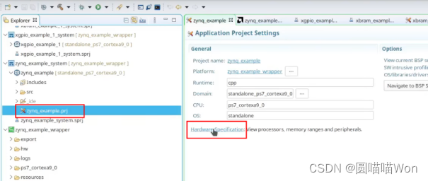
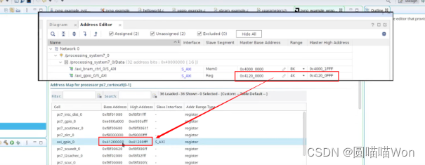
可以看到BRAM和GPIO的AXI地址:
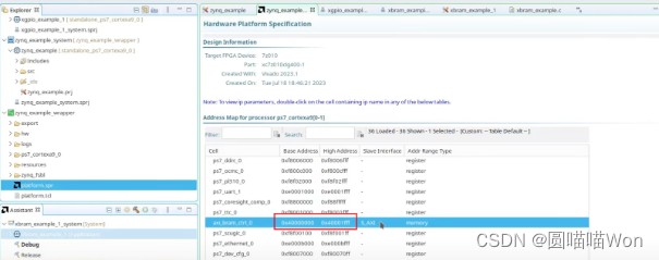
之前在Vivado中分配的地址现在也在Vitis中是可用的:
如果你想让这些地址在头文件中出现,因为你想要获取他们,可以打开parameters.h,这个头文件里面包含所有的AXI地址。如果想引用一个外设,也可以在parameters.h中使用define去引用它。
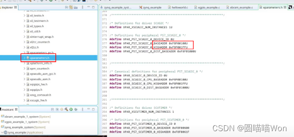
And you'll see a whole bunch of other addresses and that's just because this process has got a whole bunch of stuff on the axi bus already. These things that I added are in the PL in the fabric, but there's a bunch of other stuff that's on the axi bus that's already in the processor. So like the RAM, DDR ram. So this way we can see the axi addresses of everything.(你会看到一大堆其他地址,这只是因为在axi总线上已经有了一大堆东西。我们只是在fabric(PL)中添加了一些东西,但axi总线上还有很多其他东西,这些都已经包含在处理器中了。就像内存,DDR内存。因此我们可以看到所有东西的axi地址。)
4. 检查hello word design:

编译成功后,启动putty:
In order to access this terminal connection, I need to start PuTTY.(为了访问这个终端连接,需要启动PuTTY。)

5. 执行“launch hardware”,确保board可用:
这一步就可以将FPGA连接至电脑。因为xsa文件已经包含比特流文件了,当从Vitis去program FPGA时,it will be able to program the fabric side and also boot the standalone side.(可以program fabric端,同时也可以启动standalone端)


现在已经确保我们的board是可用的,下面就可以访问一些在fabric上的其他feature了。(memory和GPIO)
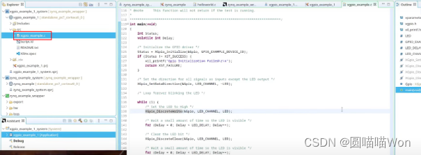
5. 初始化GPIO:
If you're not familiar with the way this works in C you create an instance of a driver object and then anytime you do anything with that specific device you access it through that driver pointer and that's really useful because then all of the information about where it is and what it's doing is all created in that little object.(如果你不熟悉C中的工作方式,你可以创建一个驱动程序对象的实例,然后通过驱动程序指针访问它,这真的很有用,因为所有关于它在哪里和做什么的信息都是在这个小对象中创建的。)

In this case the object is this GPIO guy and I need to in order to get access to that I need to copy and paste this "include" file.(在这种情况下,对象是这个GPIO,为了访问它,我需要复制并粘贴这个“include”文件,然后才可以访问这个驱动程序)

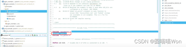
So I'm going to copy and paste the "include" file and that allows me to have access to this driver.(所以我要复制并粘贴“include”头文件,这样我就可以访问这个驱动程序。)
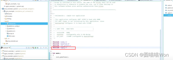
And then I'm going to copy and paste this instance(GPIO) and then I'm going to copy and paste this initialization function. (然后复制并粘贴这个实例(GPIO),拷贝并粘贴这个初始化函数。)

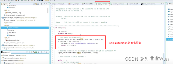
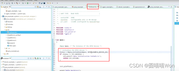
打开xparameters.h,选出base address的常量名,并填入c文件的对应参数位置:


现在就已经初始化好fabric中的GPIO IP了。
这个例子和LED有关,例子中设置了direction,并设置了LED作为输出:

从上述例子可以看出,它使用了一个指向驱动程序实例的指针,所以无论何时、做任何事情,都可以使用指针。
So I'm going to do my own thing a little bit here so I'm going to set my directions here for the LED channel and have a mask to make the LEDs output and then for the switches to make them the inputs.(这里将设置directions,并将LED的掩码作为输出,switch作为输入。)
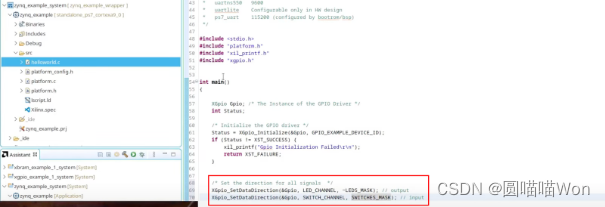
And I'm also going to put in a few defines here so I'm going to define the LED_CHANNEL as 1, and the SWITCH_CHANNEL as 2. That's because in Vivado here you can see GPIO 1 is connected to my LEDs, and GPIO2 is connected to my switches. So it's channel one and channel 2.(我也将在这里加入一些定义,我将LED_CHANNEL定义为1,SWITCH_HANNEL为2。这是因为在Vivado中,你可以看到GPIO1连接到LED,GPIO2连接到开关。因此是channel 1和channel 2。)
And we have 4 LEDs and 4 switches so we have masks of LEDs to switches F and F.(我们有4个LED和4个开关,所以我们有开关F和F的LED掩码。)


接下来连接开关和LED:
实现以下功能:开关打开,LED亮;开关关闭,LED灭。
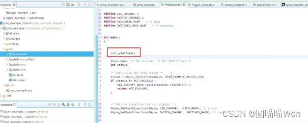
注意:initialize platform命令需要在最上面。
This initializes the printouts for the uart so currently it's using a uart for the printout so the init_platform initiates the uart. So you wanna do that at the beginning before all your printouts.(这将初始化uart的打印输出,init_platform将启动uart。所以要在打印出来之前完成。)
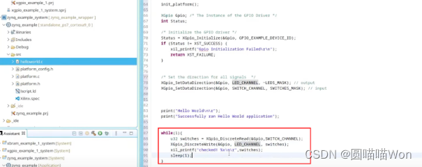
创建while循环:
What while loop does is it reads the state of my switches and then it writes that state to LED_channel and it prints out "checked". So it tells me the value of my switches. (while循环所做的是读取我的开关的状态,然后将该状态写入LED_channel,并打印出“已检查”。并告诉我开关的值。)

GPIO部分已经调试好了,接下来是BRAM部分。
6. BRAM:
include头文件:

创建对象:

打开BRAM例程中的初始化代码:
in this case you look up the config for the device and that just includes all of the information about the BRAM like how big it is and the word size and the length of it and all of that whether this ECC enabled. So this has an extra lookup config step which allows it to retrieve all of the config for BRAM. So we're going to need to create a config pointer here too for the BRAM config, and this is different from the GPIO that didn't need this.(你可以查找设备的配置,其中只包括关于BRAM的所有信息,比如它有多大、字大小和长度,以及是否启用了ECC。因此,这有一个额外的查找配置步骤,允许它检索BRAM的所有配置。因此,我们也需要在这里为BRAM配置创建一个配置指针,这与不需要它的GPIO不同。)

So for the BRAM I'm going to copy and paste both the config lookup and the config initialize because we need both of those to initialize everything.(因此,对于BRAM,我将复制并粘贴配置lookup和config初始化,因为我们需要这两者来初始化所有内容。)

BRAM初始化后,需要找到device ID去初始化这个pointer:

如何查找可用函数:
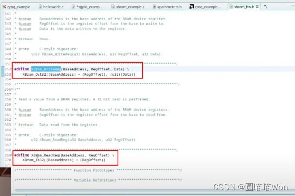
例如,如果想知道如何从BRAM中写入和读取,比如这个XBram_writeReg函数,通过右键打开函数声明的方法可以看到有声明读写函数:

另一种查找可用函数的方法是:回到.prj文件,打开BSP settings,查看文档说明,可以在文档中看到函数的声明:


接下来将使用读写函数(XBram_WriteReg和XBram_ReadReg):
创建一个写的for循环,i=i+4是因为每个word是4 bytes,即32 bits,我们每次增加4以得到下一个word。同样,也创建一个读的for循环:

We're going to write incrementing values into the memory and then we're going to read out incrementing values out of the memory.(我们将把递增的值写入内存,然后从内存中读出递增的值。)

In this video I've shown you how to take your hardware description file and put it into Vitis and play around a bit with some of the peripherals that you've included in the fabric, how to find examples, how to see the documentation and the few key areas invite us that you need to see or know about. (本视频展示了如何将硬件描述文件放入Vitis中,如何初始化并驱动一些外围设备。如何查找示例、如何查看文档以及需要查看或了解的几个关键领域。)


 6812
6812


 被折叠的 条评论
为什么被折叠?
被折叠的 条评论
为什么被折叠?
 到【灌水乐园】发言


