


1,EDID是什么?有什么用?
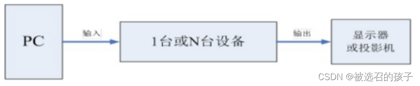
图1 应用场景
如图1所示的应用场景,PC将视频信号发送 到我们的设备上,经过一系列的传输和切换,设备将视频信号发送到显示器或者投影机上,也就是说,我们的设备位于PC和显示器之间。首先,在输入端,设备需要让PC知道自己是能够接受输入视频信号的,让PC认为自己是一台显示器。如果不这样做的话,PC可能会拒绝输出任何视频信号的(VGA接口不需要EDID也能输出)。除此之外,设备还要告诉PC自己支持的显示时序。而在输出端,当设备需要自建输出时序而不是简单的复制输入时序的适合,就需要知道显示器支持的显示时序,从而让自己输出的信号能在显示器上正常显示。在这些地方,EDID就发挥作用了。在输入端PC通过读取设备上的EDID来获悉设备支持的显示时序,而同样,在输出端设备需要读取显示器的EDID来确定自己的输出时序。注意,一个设备可能不止一个EDID,EDID是和HDMI Receiver接口绑定的,因此,可以理解为有多少个HDMI Receiver就有多少个EDID。
2,EDID Structure
| Address | No.bytes | Bytes | Description | Format | ||||||
| 00h | 8 | Bytes | Header | |||||||
| 00h | 1 | 00h | 开头8个字节为EDID的开始标志,值固定 | |||||||
| 01h | 1 | FFh | ||||||||
| 02h | 1 | FFh | ||||||||
| 03h | 1 | FFh | ||||||||
| 04h | 1 | FFh | ||||||||
| 05h | 1 | FFh | ||||||||
| 06h | 1 | FFh | ||||||||
| 07h | 1 | 00h | ||||||||
| 08h | 10 | Bytes | Vendor/Product Identification | |||||||
| 08h | 2 | ID Manufacturer Name | 制造商名称(3字母组成,5bit为1字母) | |||||||
| 0Ah | 2 | ID Product Code | 产品代码:4个16进制数,为客户提供,直接填写 | |||||||
| 0Ch | 4 | ID Serial Number | 产品的流水号(数值型),也可用字符型 | |||||||
| 10h | 1 | Week of Manufacture | 当年生产周:1-52 | |||||||
| 11h | 1 | Year of Manufacture | 生产年份:1990年开始,即1990年为0 | |||||||
| 12h | 2 | Bytes | EDID Structure Version/Revision | |||||||
| 12h | 1 | Version # | EDID 版本号 | |||||||
| 13h | 1 | Revision # | EDID 修改号 | |||||||
| 14h | 5 | Bytes | Basic Display Parameters/Features | |||||||
| 14h | 1 | Video Input Definition | 基本显示参数 | |||||||
| 15h | 1 | Max.Horizontal Image Size | 最大水平图像尺寸(单位:cm) | |||||||
| 16h | 1 | Max.Vertical Image Size | 最大垂直图像尺寸(单位:cm) | |||||||
| 17h | 1 | Display Transfer Characteristic(Gamma) | 显示传输特性:(gamma+100)/100,[1.00->3,55] | |||||||
| 18h | 1 | Feature Support | 电源管理标准 | |||||||
| 19h | 10 | Bytes | Color Characteristics | |||||||
| 19h | 1 | Red/Green Low Bits | 红绿场x,y坐标低2位值 | |||||||
| 1Ah | 1 | Blue/White Low Bits | 蓝白场x,y坐标低2位值 | |||||||
| 1Bh | 1 | Red-x | Red-x坐标 | |||||||
| 1Ch | 1 | Red-y | Red-y坐标 | |||||||
| 1Dh | 1 | Green-x | Green-x坐标 | |||||||
| 1Eh | 1 | Green-y | Green-y坐标 | |||||||
| 1Fh | 1 | Blue-x | Blue-x坐标 | |||||||
| 20h | 1 | Blue-y | Blue-y坐标 | |||||||
| 21h | 1 | White-x | White-x坐标 | |||||||
| 22h | 1 | White-y | White-y坐标 | |||||||
| 23h | 3 | Bytes | Established Timings | |||||||
| 23h | 1 | Established Timings 1 | 固定分辨率 | |||||||
| 24h | 1 | Established Timings 2 | ||||||||
| 25h | 1 | Manufacture's Reserved Timings | ||||||||
| 26h | 16 | Bytes | Standard Timing Identification | |||||||
| 26h | 2 | Standard Timing Identification 1 | 标准分辨率 | |||||||
| 28h | 2 | Standard Timing Identification 2 | ||||||||
| 2Ah | 2 | Standard Timing Identification 3 | ||||||||
| 2Ch | 2 | Standard Timing Identification 4 | ||||||||
| 2Eh | 2 | Standard Timing Identification 5 | ||||||||
| 30h | 2 | Standard Timing Identification 6 | ||||||||
| 32h | 2 | Standard Timing Identification 7 | ||||||||
| 34h | 2 | Standard Timing Identification 8 | ||||||||
| 36h | 72 | Bytes | Detailed Timing Descriptions | |||||||
| 36h | 18 | Detailed Timing Descriptions 1 | ||||||||
| 48h | 18 | Detailed Timing Descriptions 2 or Monitor Descriptor | ||||||||
| 5Ah | 18 | Detailed Timing Descriptions 3 or Monitor Descriptor | ||||||||
| 6Ch | 18 | Detailed Timing Descriptions 4 or Monitor Descriptor | ||||||||
| 7Eh | 1 | Byte | Extension Flag | Number of 128-byte EDID extension block to follow | ||||||
| 7Fh | 1 | Byte | Checksum | The 1-byte sum of all 128 bytes in this EDID block shall equal zero | ||||||
表2 EDID structure
EDID structure的结构如表2所示,主要有10部分组成。
第一个部分是:8个Bytes的Header,值固定了,用来标志EDID。
第二个部分是:10个Bytes的Vendor/Product Identification,用来描述制造厂商信息以及产品信息。
第三个部分是: 2个Bytes的EDID Structure Version/Revision,表示采用的EDID structure的版本号和修改号,和后续结构内容相对应。
第四个部分是:5个Bytes的Basic Display Parameter/Features,表示基本显示参数,图像的长宽(单位:cm),显示传输特性(一个量化后的gamma值,我也没清楚用来做什么),电源管理标准。
| Address | Describtion | 7 | 6 | 5 | 4 | 3 | 2 | 1 | 0 |
| 14h | 基本显示参数 | 模拟(0) | 信号电平 | setup(一般为0) | 同步分离 | 同步复合 | 同步SOG | 场同步起点在复合同步或SOG信号被使用 | |
| 数字(1) | 保留 | VESA DFP 1.x | |||||||
表3 基本显示参数
表3是基本显示参数的具体信息,主要分成模拟和数字两个部分。我们的HDMI传输一般都是数字信号的(第一次接触HDMI,模拟选项我没有遇到过T.T)。
| Address | Describtion | 7 | 6 | 5 | 4 | 3 | 2 | 1 | 0 |
| 18h | 电源管理标准 | Standby待机 | Suspend挂起 | Active off/low power | 显示类型 | 默认颜色空间 | 推荐分辨率 | GIF | |
表4 电源管理标准
表4是电源管理标准,里面有个推荐分辨率,就是最佳分辨率,当使用HDMI Transmitter连接上HDMI Receiver后,HDMI Transmitter会以HDMI Receiver中的推荐分辨率输出图像格式,例如,使用PC连接上一个外屏后,可以在显示设置中发现,PC显示输出调整成了外屏的推荐分辨率输出,也就是最佳分辨率输出。
第五个部分是: 10个Bytes的Color Characteristics,是使用红,绿,蓝,白四个坐标表示出了一个三角颜色空间,如下图5所示。这里我也有点迷。
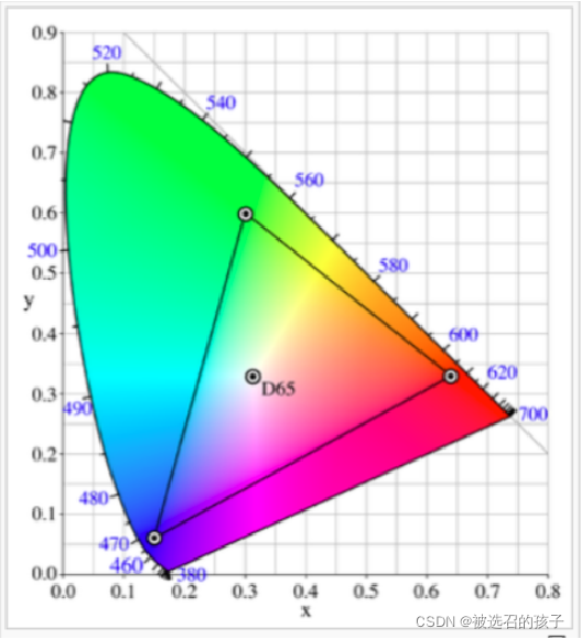
图 5
第六个部分是:3个Bytes的Established Timings,用于标志是否兼容以前显示分辨率。如下表6所示。
| Address | Describtion | 7 | 6 | 5 | 4 | 3 | 2 | 1 | 0 |
| 23h | 固定时序 | 720x400@70 | 720x400@88 | 640x480@60 | 640x480@67 | 640x480@72 | 640x480@75 | 800x600@56 | 800x600@60 |
| 24h | 固定时序 | 800x600@72 | 800x600@75 | 832x624@75 | 1024x768@87i | 1024x768@60 | 1024x768@70 | 1024x768@75 | 1280x1024@75 |
| 25h | 固定时序 | 1152x870@75 | 保留 | ||||||
表6 固定时序
第七个部分是:16 Bytes的Standard Timing Identification,即标准分辨率,使用变化的水平像素值,画面比和刷新率来表示。如下表7所示。
| Address | Describtion | 7 | 6 | 5 | 4 | 3 | 2 | 1 | 0 |
| 26h | 标准时序 | (水平活动像素/8)- 31 | |||||||
| 27h | 画面比=水平像素/垂直活动(1,3,4,9) | 刷新率(60-123Hz) | |||||||
表7 标准时序
第八个部分是:72 Bytes的Detailed Timing Descriptions/Monitor Desciptor,或者说是4个18 Bytes的Detailed Timing Descriptions/Monitor Desciptor,这里要注意的是,第一个18 Bytes必须是Detailed Timing Descriptions,后续3个18 Bytes可以是Detailed Timing Descriptions或者Mointor Desciptor中的一种。其具体格式如下表8所示。
| Address | No.bytes | Bytes | Description | Format | ||||||
| 36h | 2 | Bytes | 像素时钟/10000 | 先存储低8位 | ||||||
| 37h | ||||||||||
| 38h | 1 | Byte | 水平活动像素数 | 低8位像素数值 | ||||||
| 39h | 1 | Byte | 水平blanking | 低8位像素数值 | ||||||
| 3Ah | 1 | Byte | 水平活动+水平blankiing像素数 | 高4位:水平高4位;低4位:blanking高4位 | ||||||
| 3Bh | 1 | Byte | 垂直活动像素数 | 低8位像素数值 | ||||||
| 3Ch | 1 | Byte | 垂直blanking | 低8位像素数值 | ||||||
| 3Eh | 1 | Byte | 水平同步信号偏移量 | 低8位像素数值 | ||||||
| 3Fh | 1 | Byte | 水平同步信号脉冲宽度 | 低8位像素数值 | ||||||
| 40h | 1 | Byte | 垂直同步偏移+垂直同步脉冲宽度 | 高4位:垂直低4位同步偏移;低4位:垂直低4位同步脉冲宽度 | ||||||
| 41h | 1 | Byte | 水平同步信号偏移量;水平同步信号脉冲宽度;垂直同步信号偏移量;垂直同步信号脉冲宽度 | 6,7:水平同步偏移量;4,5:水平同步脉冲宽度;2,3:垂直同步偏移量;1,0:垂直同步脉冲宽度 | ||||||
| 42h | 1 | Byte | 水平图像尺寸 | 低8位(单位:mm) | ||||||
| 43h | 1 | Byte | 垂直图像尺寸 | 低8位(单位:mm) | ||||||
| 44h | 1 | Byte | 水平&垂直图像尺寸 | 高4位:水平图像;低4位:垂直图像 | ||||||
| 45h | 1 | Byte | Horizontal Border | |||||||
| 46h | 1 | Byte | Vertical Border | |||||||
| 47h | 1 | Byte | 标志位 | |||||||
表8 详细时序定义
第九个部分是: 1 Byte的Extension Flag,该Byte中标志是否有扩展128 Bytes的内容,即可用来区分是128 Bytes的EDID,还是256 Bytes的E-EDID。
第十部分是: 1Byte的Checksum,用来保证前128 Bytes的值的累加和为0。
对于EDID而言,很重要的是Timing(分辨率)的区分,在EDID中Timing有4个Timing的定义。1,在Basic Display Parameters中的电源管理标准中有一个推荐显示分辨率,也就是最佳显示分辨率。2,在Established Timings中,用与标识Receiver是否支持历史遗留(legacy Timing)的显示分辨率。3,在Standard Timings中,使用转换后的水平像素,画面比,刷新率定义的显示分辨率。4,在Detailed Timing Descriptions中,详细定义的显示分辨率。这里定义的显示分辨率和3D 视频格式的分辨率没有关系。
3,E-EDID Structure
当EDID中的Extension Flag标识具有扩展128 Bytes内容时,该EDID Structure为E-EDID Structure。后续的128 Bytes内容如下表8所示。
| Address(+80H) | Values | Description | Format | ||||||
| 00h | 02h | Tag | 固定为02h,EDID标志分配给CEA-861x | ||||||
| 01h | 03h | 版本号 | CEA扩展版本号--03 | ||||||
| 02h | DTD起始地址,暂用d表示 | d为扩展块中DTD开始地址 | |||||||
| 03h | Native DTD数量及YCbCr444/422,过扫描支持设置 | 7:过扫描;6:basic audio;5:YCbCr444;4:YCbCr422;DTD个数 | |||||||
| <d | 各功能块参数设置 | Video Data Block;Audio Data Block;Speaker Allocation Data Block;Vendor Specific Data Block | |||||||
| d | DTD起始地址,一个DTD为18字节 | DTD | |||||||
| d+(n*18) | 00h | 剩下的保留 | 00h填充 | ||||||
| 7Fh | Check Sum | ||||||||
表9 E-EDID Structure
E-EDID的结构如表9所示,主要由7部分组成。
第一个部分是1 Byte的Tag号,其值固定为0x2H。
第二个部分是1 Byte的版本号,表示CEA扩展版本,这里用的是0x3h,该值会影响功能块的结构。
第三个部分是1 Byte的DTD(Detailed Timing Descriptions)的起始地址。
第四个部分是1 Byte中第7位表示是否支持过扫描,第6位标识基本audio格式支持,第5位标识YCbCr444颜色空间采样格式支持,第4位标识YCbCr422颜色空间采样格式支持,第3-0位标识DTD的个数。
第五个部分是各种功能块参数设置,
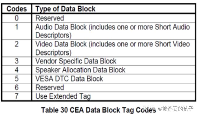
表 10 CEA Data Block Tag Codes
功能块的Tag编码如表10所示,该Tag值在功能块首字节的第7-5bits来标识。功能模块的基本结构如下表11所示。
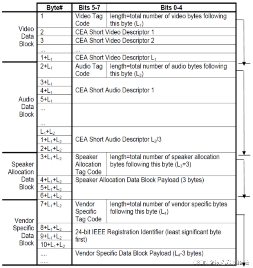
表11 功能块基本结构
1,Video Data Block,根据Data block结构,首字节的bit7-5为video data block=2,bit4-0为video data block长度,后面跟的字节为多个CEA short Video Desriptor。CEA short Video Desriptor如表12所示。
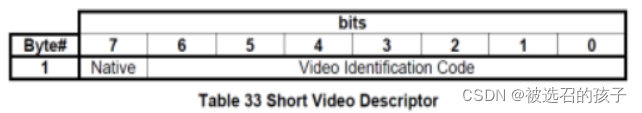
表12 CEA short Video Descriptor
在CEA short Video Descriptor中的VIC(Video Identification Code)定义如表13所示。
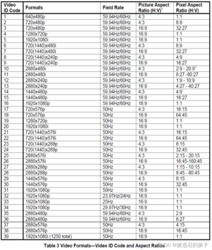
表13 VIC
2,Audio Data Block:根据Data Block结构,首字节的bit7-5为Audio Data Block=1,bit4-0为Video Data Block长度,后面跟的字节为1个或多个CEA short Audio Descriptor,每个CEA short Audio Descriptor由3个字节组成,分为LPCM,AC3,MPEG2等各种Audio Format Code。 如表14所示。
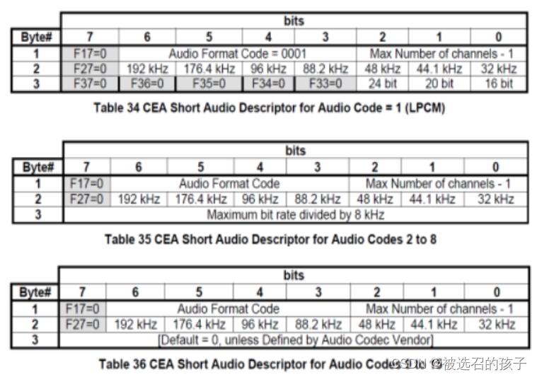
表14 CEA short Audio Descriptor
在CEA short Audio Descriptor中的Audio Format Code定义如下表15所示。
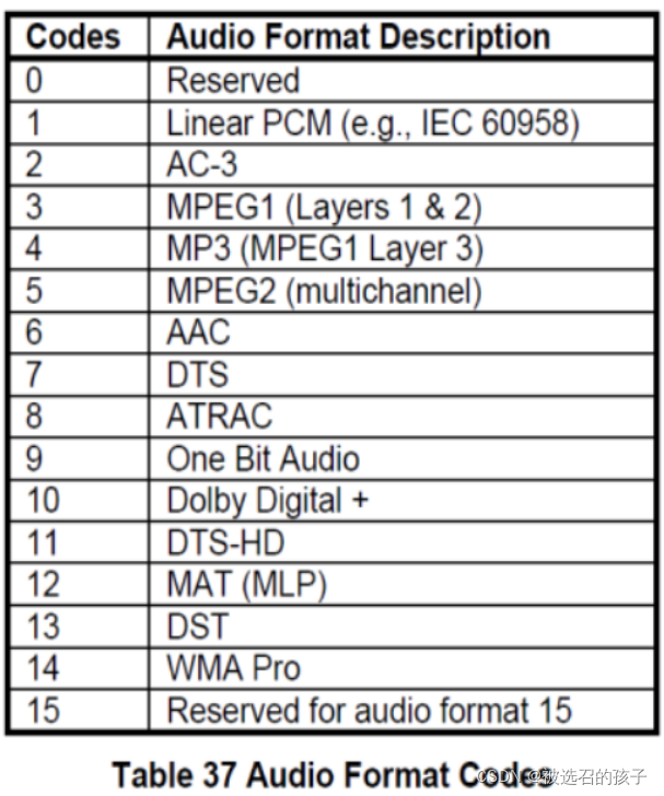
表15 Audio Format Codes
3,Speaker Allocation Data Block,根据Data Block结构,首字节的bit7-5为Speaker Allocation Data Block=4,bit 4-0为Speaker Allocation Data长度(固定为3),后面跟的3字节,结构如表16所示,这里应该是用来定义Receiver音响的位置。
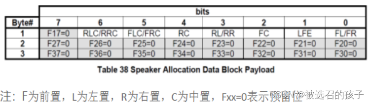
表16 Speaker Allocation Data Block
4,Vendor-Specific Data Block,结构如表17所示。
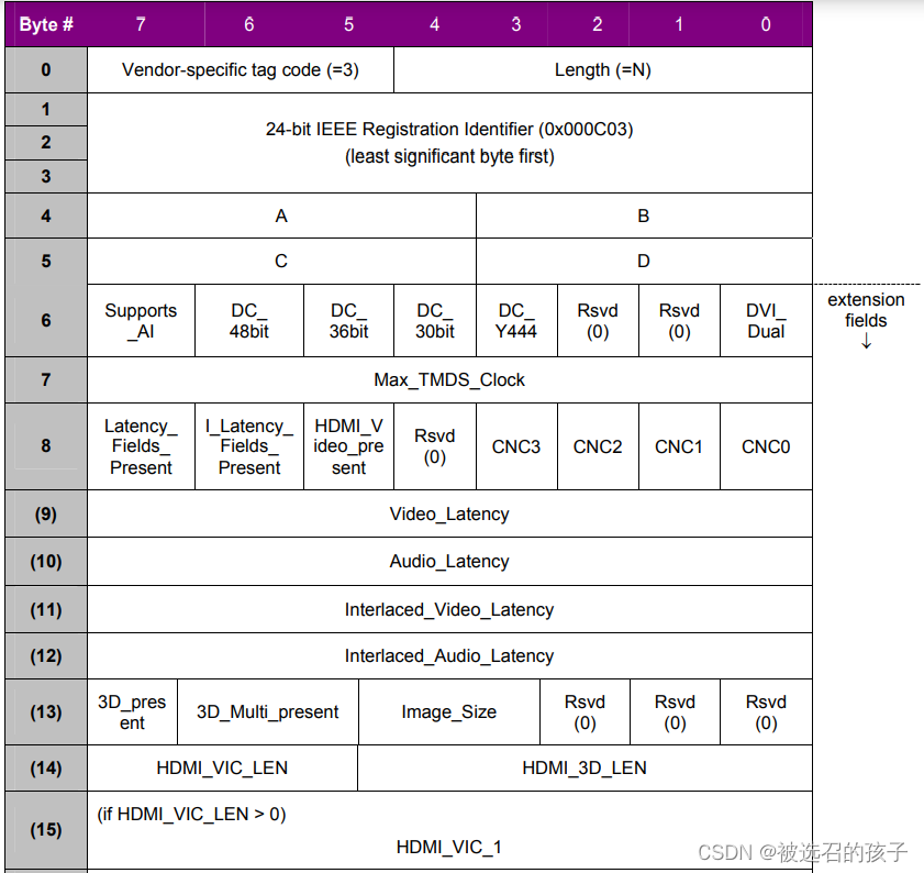
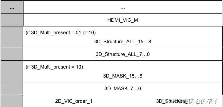
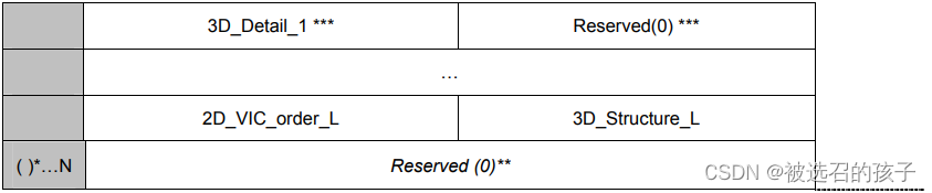
表17 Vendor-Specific Data Block
该功能块结构标识了Receiver对3D 视频帧格式的支持。其中3D_present位表示HDMI Receiver是否支持3D视频格式。3D_Multi_present表示后续结构对3D_Structure_ALL和3D_Structure_Mask如何显示。
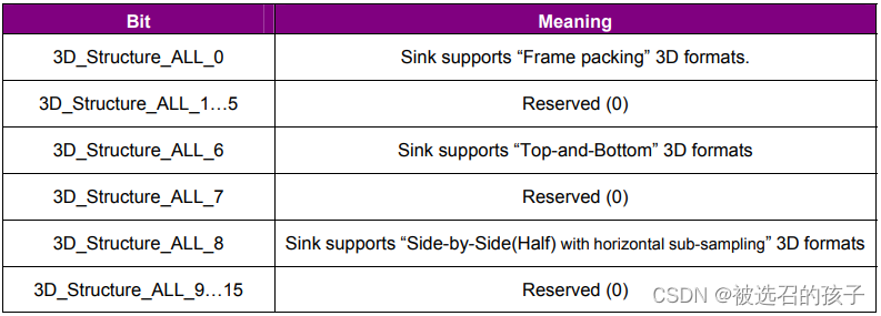
表18 3D_Structure_All
3D_Structure_All的结构如表18所示,16位中只有三位标识3D格式,分别为Frame packing, Top-and-Bottom,Side-by-Side的3D格式,Frame packing的3D帧格式是上下帧为一帧数据,水平方向没有像素扩展,在垂直方向像素数扩展了一倍,中间用Active space隔开。Top-and-Bottom的3D帧格式也是上下分帧,和Frame packing不同的是,在垂直方向并没有像素数的扩展。Side-by-Side的3D帧格式是左右分帧,和Top-and-Bottom一样,和原2D格式大小相同,在水平和垂直方向没有像素数的扩展。具体的3D帧格式可以参考HDMI Spec,后续会单独介绍。
这里要注意的是除了3D_Structure_ALL设置Receiver(Sink)对3D 帧格式的支持后,还要设置3D_Structure_Mask来表示设置的3D_Structure_All设置的3D帧格式是有效的。
第六部分就是DTD(Detailed Timing Descriptions),其起始偏移地址应该和offset=0x2h中给出的DTD起始地址相同,DTD的个数则和0x3h中的bit3-bit0标识的个数相同,DTD的具体格式和EDID中的DTD相同。
第七部分是DTD未将后续存储占满,则用0填充。
第八部分是一个Byte的Checksum,与EDID中Checksum相同,保证128 Bytes数据相加和为0。


 4367
4367

 被折叠的 条评论
为什么被折叠?
被折叠的 条评论
为什么被折叠?
 到【灌水乐园】发言


