


介绍
算术逻辑单元,就是一种可以执行算术运算和逻辑运算操作的电路。为了区分电路进行算术运算还是逻辑运算,我是通过一个复用器来实现的。
电路展示
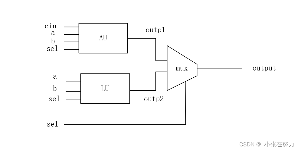
图中,AU指的是算术单元,LU指的是逻辑单元,可以看到后面有一个复用器,用于区分算术运算还是逻辑运算。
在这里我孩展示一下真值表的,有点懒得做了,emmm大家看代码吧,也很好理解。
设计文件
设计文件可以在一个vhd文件中完成的,我为了让整个设计清晰一些吧,这里采用了模块化的设计,所以会有多个hdl文件。
顶层文件
library ieee;
use ieee.std_logic_arith.all;
use ieee.std_logic_1164.all;
entity alu is
port( a,b : in std_logic_vector(7 downto 0);
sel1 : in std_logic_vector(2 downto 0);
sel : in std_logic;
cin : in std_logic;
output : out std_logic_vector(7 downto 0));
end alu;
architecture alu of alu is
component logical_unite is
port( a,b : in std_logic_vector(7 downto 0);
sel1 : in std_logic_vector(2 downto 0);
outp2 : out std_logic_vector(7 downto 0));
end component logical_unite;
component arith_unite is
port( a,b : in std_logic_vector(7 downto 0);
sel1 : in std_logic_vector(2 downto 0);
cin : in std_logic;
outp1 : out std_logic_vector(7 downto 0));
end component arith_unite;
component mux is
port( inp1 : in std_logic_vector(7 downto 0);
inp2 : in std_logic_vector(7 downto 0);
sel : in std_logic;
output : out std_logic_vector(7 downto 0));
end component mux;
signal inp1 : std_logic_vector(7 downto 0);
signal inp2 : std_logic_vector(7 downto 0);
signal outp1 : std_logic_vector(7 downto 0);
signal outp2 : std_logic_vector(7 downto 0);
begin
u1 : arith_unite
port map(a => a,
b => b,
sel1 => sel1,
cin => cin,
outp1 => outp1);
u2 : logical_unite
port map(a => a,
b => b,
sel1 => sel1,
outp2 => outp2);
u3 : mux
port map(inp1 => outp1,
inp2 => outp2,
sel => sel,
output => output);
end architecture alu;
逻辑运算单元
library ieee;
use ieee.std_logic_arith.all;
use ieee.std_logic_1164.all;
entity logical_unite is
port( a,b : in std_logic_vector(7 downto 0);
sel1 : in std_logic_vector(2 downto 0);
outp2 : out std_logic_vector(7 downto 0));
end logical_unite;
architecture logical_unite of logical_unite is
begin
with sel1(2 downto 0) select
outp2 <= not a when "000",
not b when "001",
a and b when "010",
a or b when "011",
a nand b when "100",
a nor b when "101",
a xor b when "110",
not(a xor b) when others;
end architecture logical_unite;
算术运算单元
library ieee;
use ieee.std_logic_arith.all;
use ieee.std_logic_1164.all;
use ieee.std_logic_signed.all;
entity arith_unite is
port( a,b : in std_logic_vector(7 downto 0);
cin : in std_logic;
sel1 : in std_logic_vector(2 downto 0);
outp1 : out std_logic_vector(7 downto 0));
end arith_unite;
architecture arith_unite of arith_unite is
begin
with sel1(2 downto 0) select
outp1 <= a when "000",
a+1 when "001",
a-1 when "010",
b when "011",
b+1 when "100",
b-1 when "101",
a+b when "110",
a+b+cin when others;
end architecture arith_unite;
2路复用器
library ieee;
use ieee.std_logic_1164.all;
entity mux is
port( inp1 : in std_logic_vector(7 downto 0);
inp2 : in std_logic_vector(7 downto 0);
sel : in std_logic;
output : out std_logic_vector(7 downto 0));
end mux;
architecture mux of mux is
begin
with sel select
output <= inp1 when '0',
inp2 when others;
end architecture mux;
仿真文件
library ieee;
use ieee.std_logic_arith.all;
use ieee.std_logic_1164.all;
entity tb_alu is
end tb_alu;
architecture alu of tb_alu is
component alu is
port( a,b : in std_logic_vector(7 downto 0);
sel1 : in std_logic_vector(2 downto 0);
cin : in std_logic;
sel : in std_logic;
output : out std_logic_vector(7 downto 0));
end component alu;
signal a,b,output : std_logic_vector(7 downto 0);
signal sel1 : std_logic_vector(2 downto 0);
signal sel : std_logic;
signal cin : std_logic;
begin
dut : alu
port map(a => a,
b => b,
sel1 => sel1,
sel => sel,
cin => cin,
output => output
);
process
begin
a <= "00001011";
b <= "10000111";
sel <= '0';
cin <= '0';
sel1 <= "011";
wait for 20ns;
cin <= '1';
wait for 20ns;
sel <= '1';
a <= "01101011";
b <= "10110111";
sel1 <= "110";
wait for 20ns;
end process;
end architecture alu;
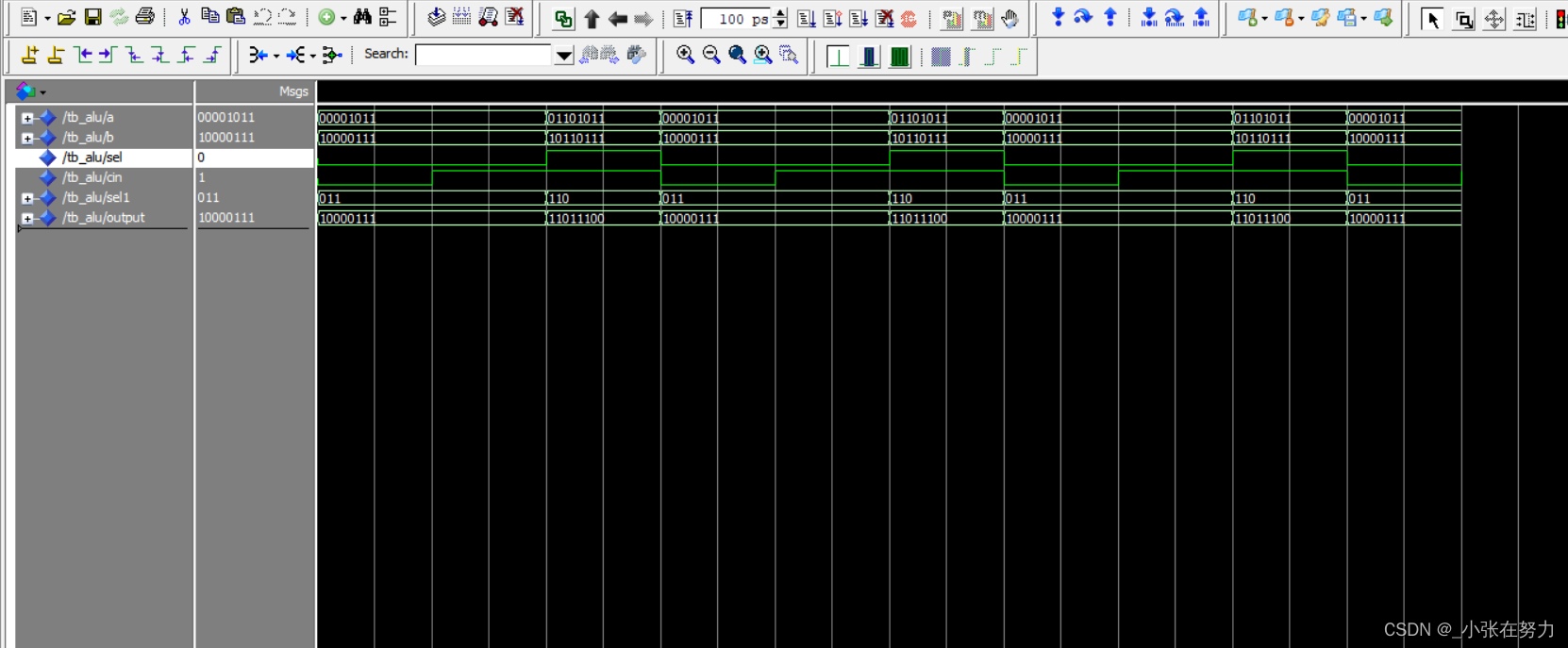
仿真结果
结语
ALU的仿真结果大家可以自己多用不同的输入试试,在这里我使用的输入有点少了。
其实原理真的挺简单的,但是我找错误找到自己想哭,有些代码本来写的就是错的,然后后来都是复制的错的,害,要仔细。
有什么问题大家留言吧,欢迎指正。


 830
830

 被折叠的 条评论
为什么被折叠?
被折叠的 条评论
为什么被折叠?
 到【灌水乐园】发言


