


Sim/circuit1
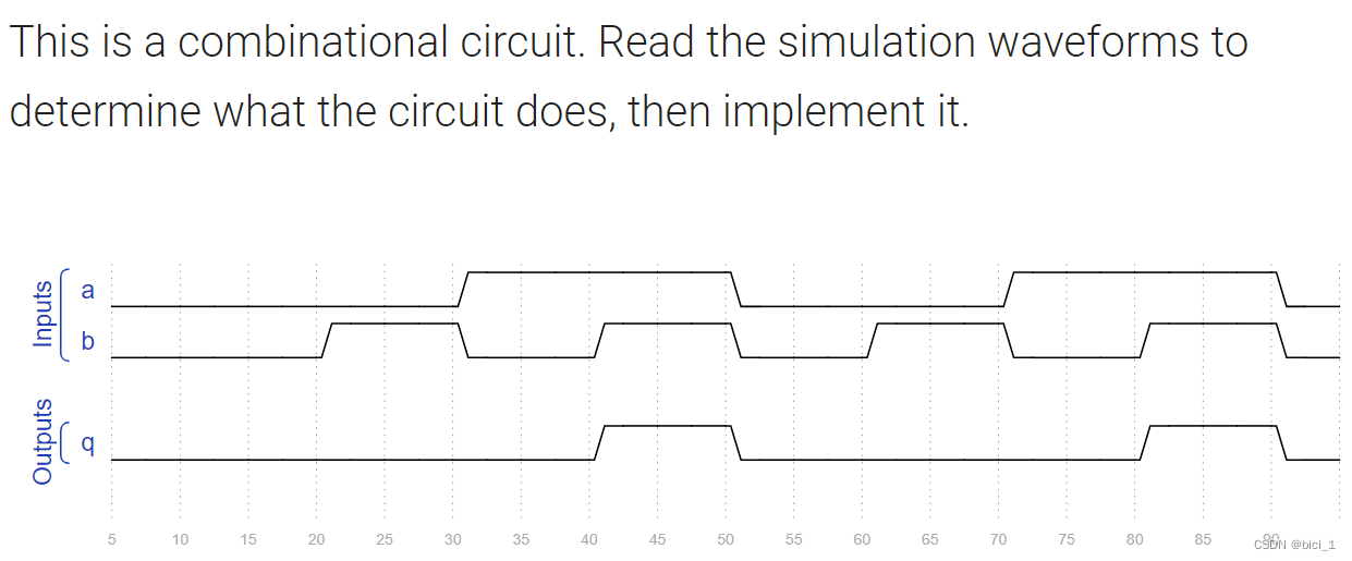
代码如下:
module top_module (
    input a,
    input b,
    output q );//

    assign q = a && b ; // Fix me

endmodule
Sim/circuit2
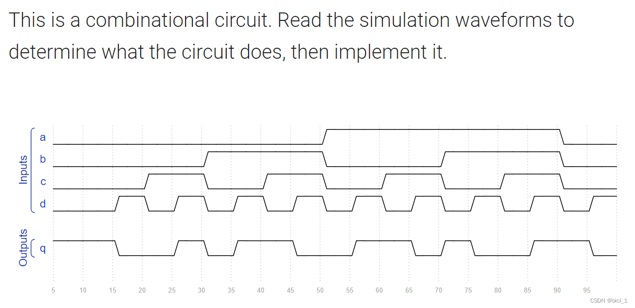
代码如下:
module top_module (
    input a,
    input b,
    input c,
    input d,
    output q );//

    assign q = ~(a^b^c^d) ; // Fix me

endmodule
Sim/circuit3
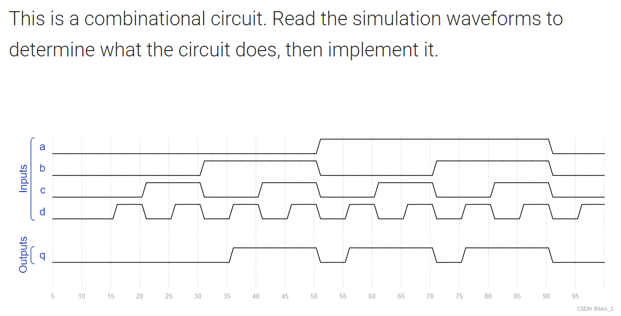
代码如下:
module top_module (
    input a,
    input b,
    input c,
    input d,
    output q );//

    assign q = (b&&d) || (a&&d) || (b&&c) || (a&&c) ; // Fix me

endmodule
Sim/circuit4
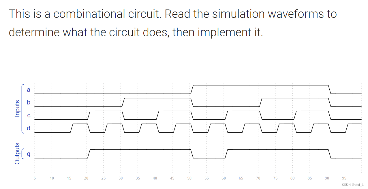
代码如下:
module top_module (
    input a,
    input b,
    input c,
    input d,
    output q );//

    assign q = b || c ; // Fix me

endmodule
Sim/circuit5
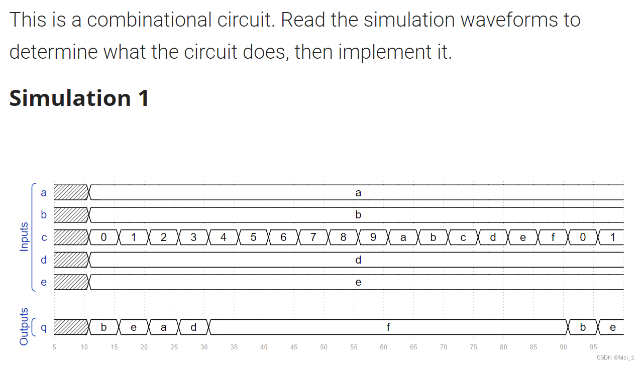
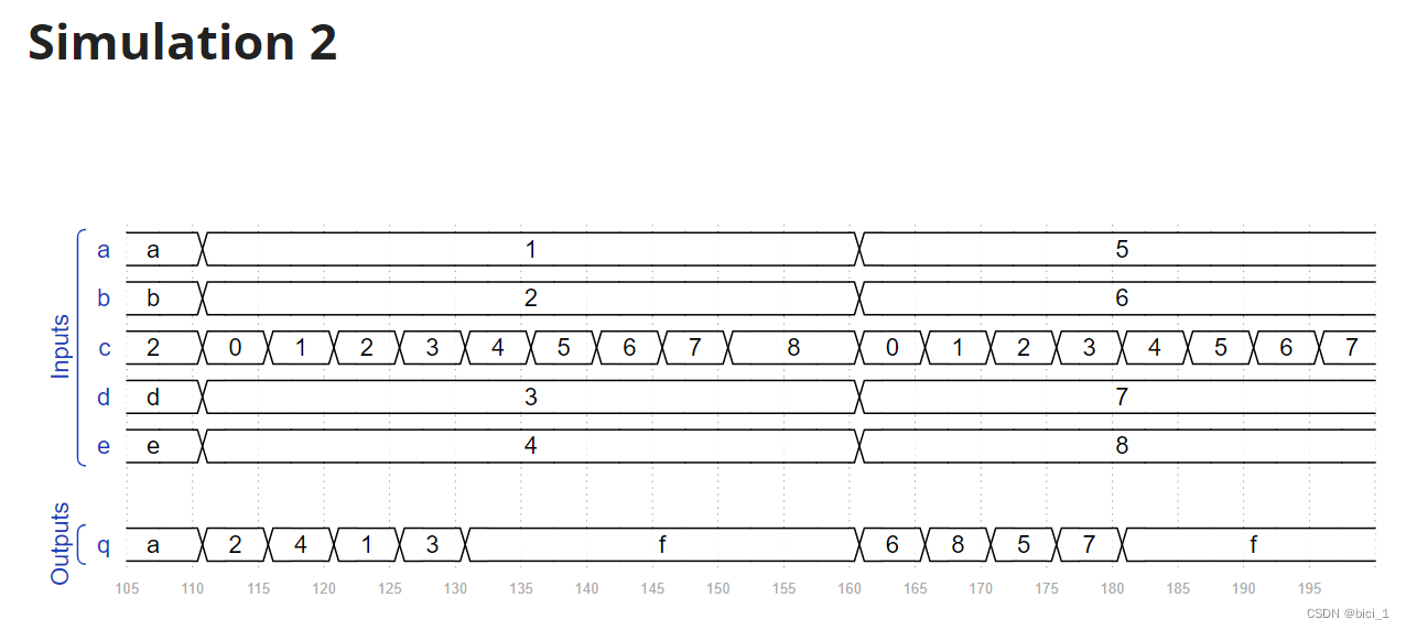
代码如下:
module top_module (
    input [3:0] a,
    input [3:0] b,
    input [3:0] c,
    input [3:0] d,
    input [3:0] e,
    output [3:0] q );

    always@(*) begin
        case(c)
            4'd0: q = b ;
            4'd1: q = e ;
            4'd2: q = a ;
            4'd3: q = d ;
            default: q = 4'hf ;
        endcase
    end

endmodule
Sim/circuit6
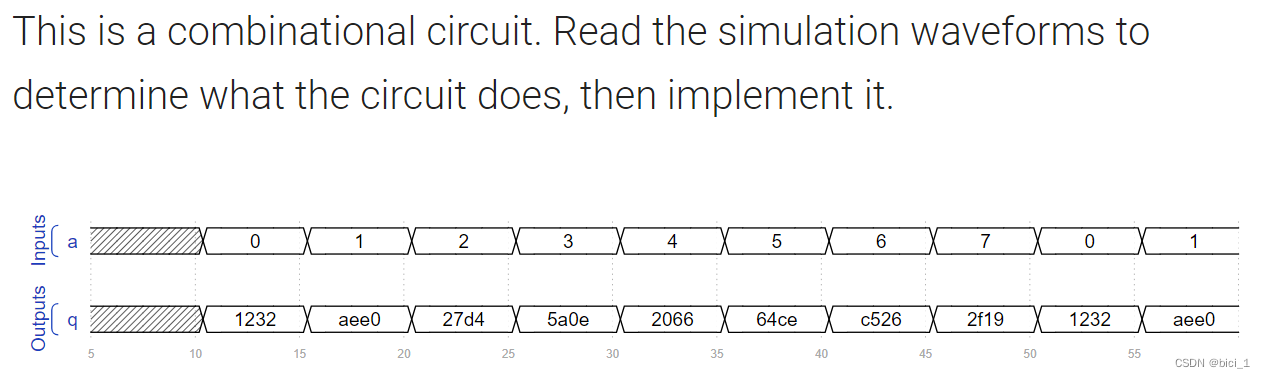
代码如下:
module top_module (
    input [2:0] a,
    output [15:0] q );

	always @(*) begin
		case(a)
			0:  q = 16'h1232 ;
			1:  q = 16'haee0 ;
			2:  q = 16'h27d4 ;
			3:  q = 16'h5a0e ;
			4:  q = 16'h2066 ;
			5:  q = 16'h64ce ;
			6:  q = 16'hc526 ;
			7:  q = 16'h2f19 ;
            default: q = 16'd0 ;
		endcase
	end
endmodule
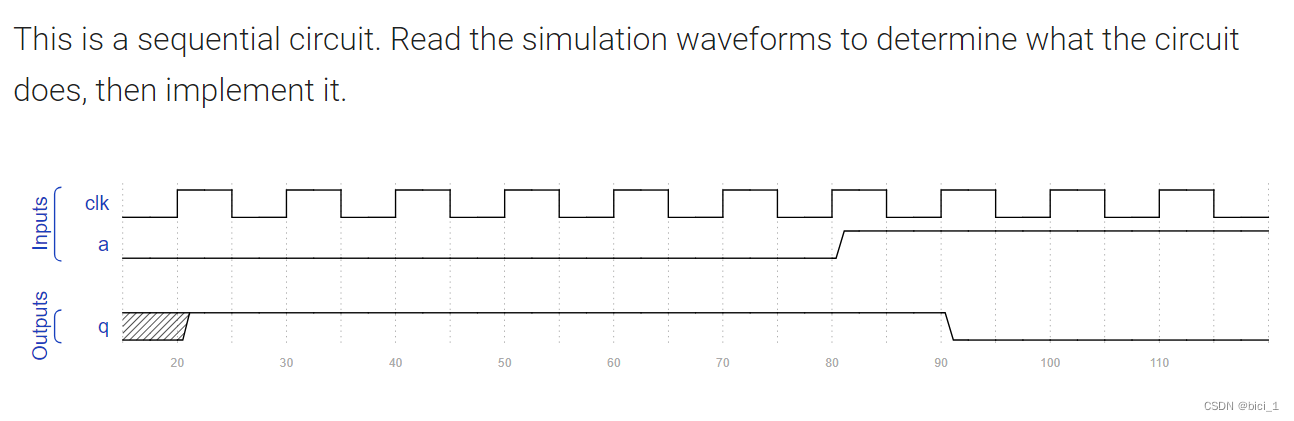
Sim/circuit7
代码如下:
module top_module (
    input clk,
    input a,
    output q );
    always@(posedge clk) begin
        if(a) begin
            q <= 1'b0 ;
        end else begin
            q <= 1'b1 ;
        end
    end
endmodule
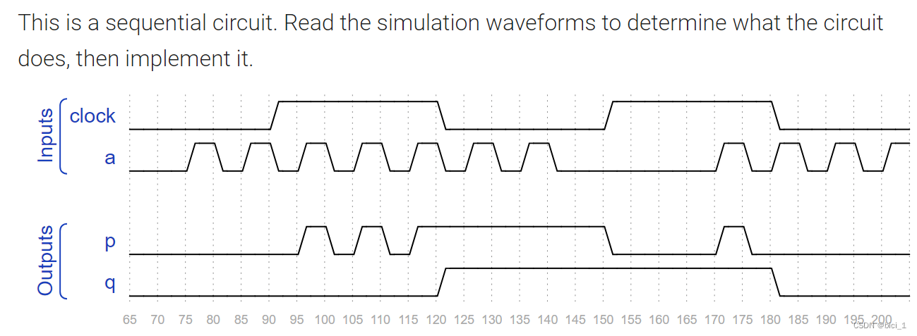
Sim/circuit8
代码如下:
module top_module (
    input clock,
    input a,
    output p,
    output q );
	always @(*) begin
		if (clock) begin
			p = a;
		end else begin
			p = p;
		end
	end
	always @(negedge clock) begin
		q <= a;
	end
endmodule
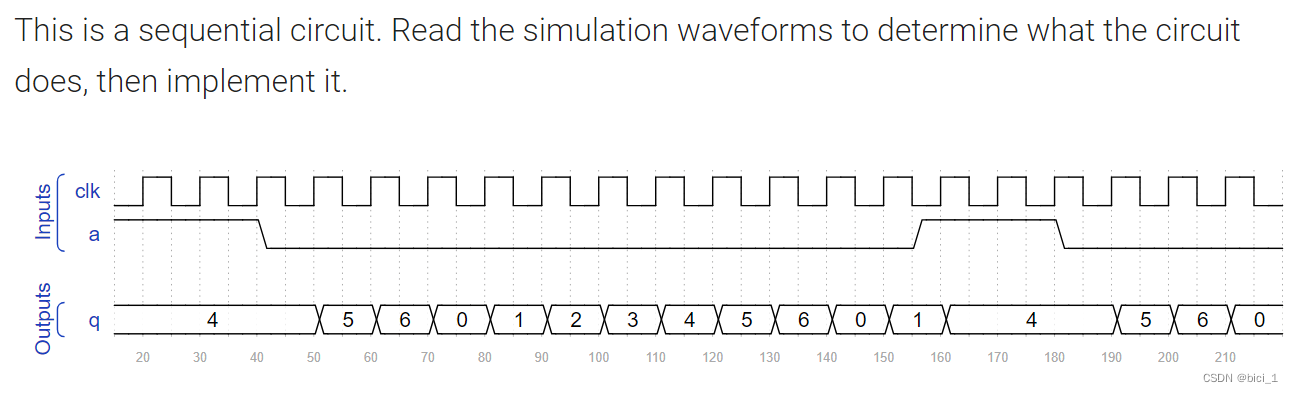
Sim/circuit9
代码如下:
module top_module (
    input clk,
    input a,
    output [3:0] q );
    always@(posedge clk) begin
        if(a) begin
            q <= 4'd4 ;
        end else if(q <= 4'd5) begin
            q <= q + 4'd1 ;
        end else begin
            q <= 4'd0 ;
        end
    end

endmodule
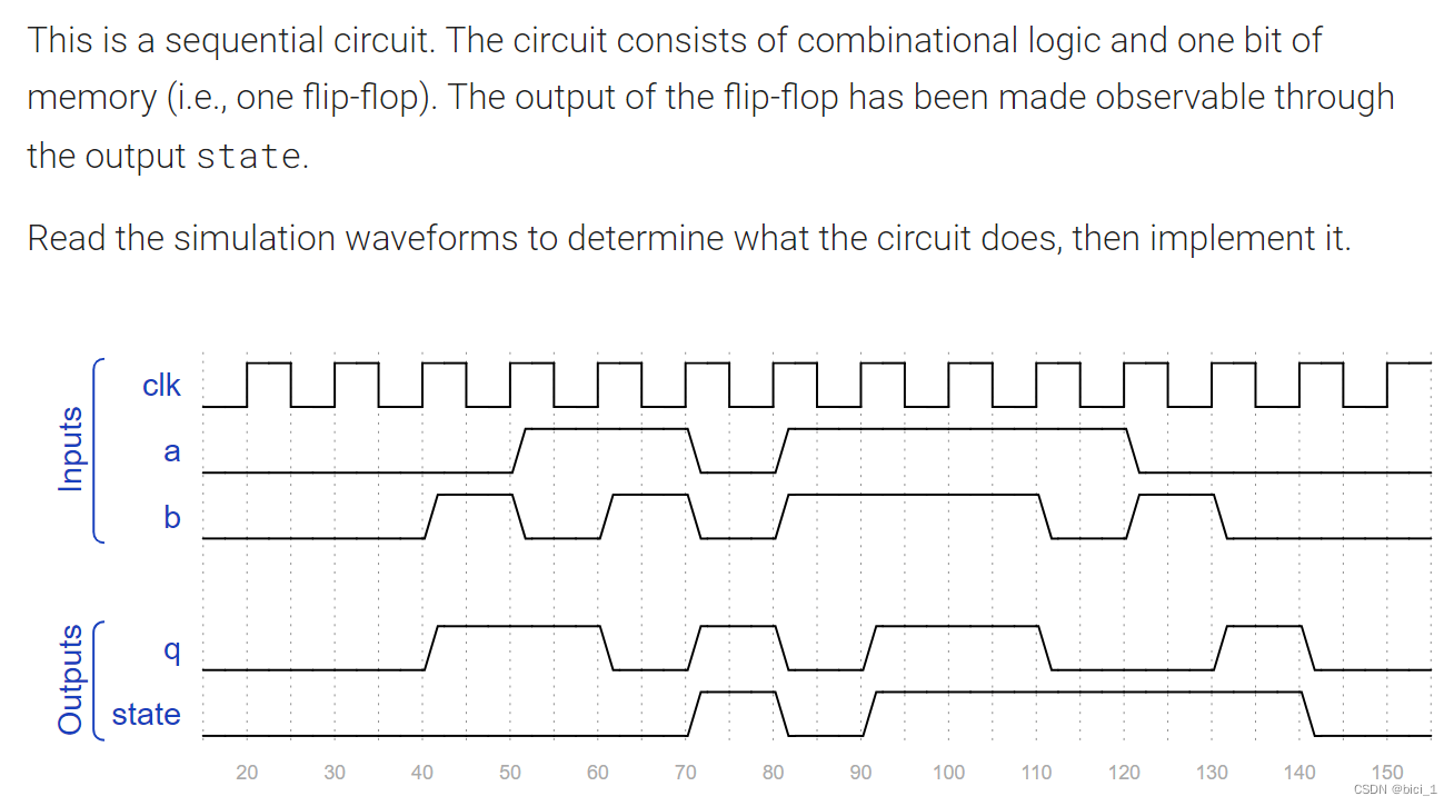
Sim/circuit10
代码如下:
module top_module (
    input clk,
    input a,
    input b,
    output q,
    output state  );
    assign q = a^b^state;

	always @(posedge clk) begin
        if (a && b) begin
			state <= 'd1;
        end else if ( ~a && ~b ) begin
			state <= 'd0;
		end else begin
			state <= state;
		end
	end

endmodule


 425
425

 被折叠的 条评论
为什么被折叠?
被折叠的 条评论
为什么被折叠?
 到【灌水乐园】发言


