


需求1:使用脉冲边沿检测法设计一个上下降沿检测功能
使用脉冲边沿检测法设计一个上下降沿检测功能

1,使用clk 脉冲来临时pluse 移位赋值
preg1 <=pluse
preg2<=preg2
preg1 比pluse 晚一个时钟,
preg2比preg1晚一个时钟
在利用 与/非指令合并,生成上升沿的一个脉冲的
r_pluse <= {r_pluse[0],pulse}; //等效于
r_pluse[0] <=pluse
r_pluse[1] <=r_pluse[1]
2,代码实现
vlg_design
/
/*
使用脉冲边沿检测法设计一个上下降沿检测功能
 */
/
`timescale 1ns/1ps
module vlg_design(
    input clk,//100M
    input pulse,//
    input rest_n,
    output  o_pulse_pos, //输出pluse 的上升沿脉冲
    output  o_pulse_nes  //输出pluse 的下降沿脉冲
    );


reg [1:0] r_pluse;

 //产生1s的计数
 always @(posedge clk) begin
    if(!rest_n) r_pluse <='b00;
    else  r_pluse <= {r_pluse[0],pulse};
 end

assign  o_pulse_pos = r_pluse[0] & ~r_pluse[1];
assign  o_pulse_nes = r_pluse[1] & ~r_pluse[0];

endmodule
testbench_top
`timescale 1ns/1ps
module testbench_top();


//参数定义

`define CLK_PERIORD        10        //时钟周期设置为10ns(100MHz)


//接口申明

reg clk;
reg pulse;
reg rest_n;
wire o_pulse_pos;
wire o_pulse_nes;


vlg_design        uut_vlg_design(
    .clk(clk),
    .pulse(pulse),
    .rest_n(rest_n),
    .o_pulse_pos(o_pulse_pos),
    .o_pulse_nes(o_pulse_nes)
    );

//时钟和复位初始化、复位产生
initial begin
clk <= 0;
rest_n <= 0;
#10;
rest_n <= 1;
clk <= 1;
pulse <= 1'b0;

end

//时钟产生
always #(`CLK_PERIORD/2) clk = ~clk;


//测试激励产生
initial begin

    @(posedge rest_n);    //等待复位完成
    @(posedge clk);
    pulse <= 1'b0;
    repeat(10) @(posedge clk);
    pulse <= 1'b1;


    repeat(30) @(posedge clk);
    pulse <= 1'b0;
    repeat(10) @(posedge clk);

    $stop;
end

endmodule
3,仿真效果

需求2:使用脉冲边沿检测法设计一个双沿检测功能
/
/*
使用脉冲边沿检测法设计一个上下降沿检测功能

 */
/
`timescale 1ns/1ps
module vlg_design(
    input clk,//100M
    input pulse,//
    input rest_n,
    output  o_pulse_pos, //输出pluse 的上升沿脉冲
    output  o_pulse_nes , //输出pluse 的下降沿脉冲
    output  o_pulse_both  //输出pluse 的上升下降沿脉冲
    );


reg [1:0] r_pluse;

 //产生1s的计数
 always @(posedge clk) begin
    if(!rest_n) r_pluse <='b00;
    else  r_pluse <= {r_pluse[0],pulse};
 end

assign  o_pulse_pos = r_pluse[0] & ~r_pluse[1];
assign  o_pulse_nes = r_pluse[1] & ~r_pluse[0];
assign o_pulse_both = o_pulse_pos | o_pulse_nes;
endmodule
`timescale 1ns/1ps
module testbench_top();


//参数定义

`define CLK_PERIORD        10        //时钟周期设置为10ns(100MHz)


//接口申明

reg clk;
reg pulse;
reg rest_n;
wire o_pulse_pos;
wire o_pulse_nes;
wire o_pulse_both;


vlg_design        uut_vlg_design(
    .clk(clk),
    .pulse(pulse),
    .rest_n(rest_n),
    .o_pulse_pos(o_pulse_pos),
    .o_pulse_nes(o_pulse_nes),
    .o_pulse_both(o_pulse_both)
    );

//时钟和复位初始化、复位产生
initial begin
clk <= 0;
rest_n <= 0;
#10;
rest_n <= 1;
clk <= 1;
pulse <= 1'b0;

end

//时钟产生
always #(`CLK_PERIORD/2) clk = ~clk;


//测试激励产生
initial begin

    @(posedge rest_n);    //等待复位完成
    @(posedge clk);
    pulse <= 1'b0;
    repeat(10) @(posedge clk);
    pulse <= 1'b1;


    repeat(30) @(posedge clk);
    pulse <= 1'b0;
    repeat(10) @(posedge clk);

    $stop;
end

endmodule

3思考:FPGA并行性


3次测试中,测试1,测试2 ,实现了和r_pluse <= {r_pluse[0],pulse}; 同样的效果。
测试3中,体现了expriment1/expriment2 赋值的并行性
测试1,2 其实也是并行的,

第二条语句中的test2 赋值和第一条语句的test1 同时赋值,此时的test1还未被改变。故时序上出现了移位的效果
4,脉冲边沿检测的适用场景
STAR FPGA开发板的按键消抖的按键检测(at7_ex07)

频率计数
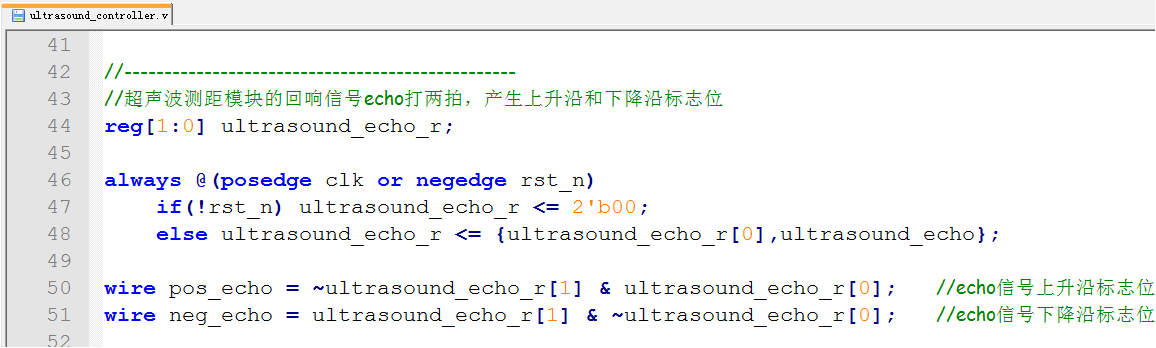
STAR FPGA开发板的超声波回响脉冲的高电平时间计数 (at7_ex11)


 759
759


 被折叠的 条评论
为什么被折叠?
被折叠的 条评论
为什么被折叠?
 到【灌水乐园】发言


