


Bloom
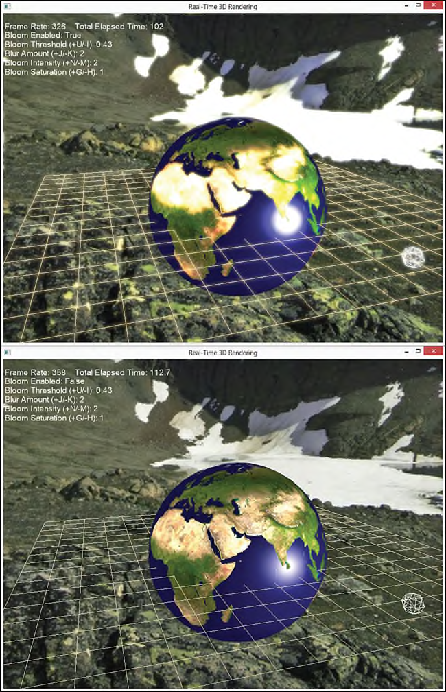
高斯模糊effect有各种各样的应用。比如,可以用于区分场景中背景objects(通过模糊处理使得objects呈现出一种失去焦点的现象)和前景objects(没有模糊处理)。另外还可以用于bloom(曝光) effect中,一种bloom effect通过增强场景中明亮的区域来模拟真实世界中的照相机。图18.6显示了在一个场景中使用曝光(上图)和不使用曝光effect的输出结果。
使用如下的步骤可以创建一种bloom effect:
1、把场景绘制到一个off-screen render target中。
2、从场景图像中提取明亮的斑点保存到一个off-screen render target(创建一个glow map)中。
3、对glow map进行模糊处理并保存到一个off-screen render target中。
4、把经过模糊处理后的glow map与原始的scene texture进行合并,并把结果渲染到屏幕上。
列表18.12列出了Bloom.fx effect的代码。其中包含了三个独立的techniques:一个用于从输入的texture中提取出明亮的区别,创建一个曝光贴图(glow map),另一个是把模糊处理后的glow map与原始的scene texture进行合并,第三个是渲染未经过修改的原始scene texture。在Bloom.fx effect中没有复制高斯模糊的代码,因为可以在应用程序中直接使用前面编写的高斯模糊component对提取出的glow map进行模糊处理。
列表18.12 The Bloom.fx Effect
/************* Resources *************/

static const float3 GrayScaleIntensity = { 0.299f, 0.587f, 0.114f };

Texture2D ColorTexture;
Texture2D BloomTexture;

cbuffer CBufferPerObject
{
    float BloomThreshold = 0.3f;
    float BloomIntensity = 1.25f;
    float BloomSaturation = 1.0f;
    float SceneIntensity = 1.0f;
    float SceneSaturation = 1.0f;
};

SamplerState TrilinearSampler
{
    Filter = MIN_MAG_MIP_LINEAR;
    AddressU = WRAP;
    AddressV = WRAP;
};

/************* Data Structures *************/

struct VS_INPUT
{
    float4 Position : POSITION;
    float2 TextureCoordinate : TEXCOORD;
};

struct VS_OUTPUT
{
    float4 Position : SV_Position;
    float2 TextureCoordinate : TEXCOORD;
};

/************* Utility Functions *************/

float4 AdjustSaturation(float4 color, float saturation)
{
    float intensity = dot(color.rgb, GrayScaleIntensity);

    return float4(lerp(intensity.rrr, color.rgb, saturation), color.a);
}

/************* Vertex Shader *************/

VS_OUTPUT vertex_shader(VS_INPUT IN)
{
    VS_OUTPUT OUT = (VS_OUTPUT)0;

    OUT.Position = IN.Position;
    OUT.TextureCoordinate = IN.TextureCoordinate;

    return OUT;
}

/************* Pixel Shaders *************/

float4 bloom_extract_pixel_shader(VS_OUTPUT IN) : SV_Target
{
    float4 color = ColorTexture.Sample(TrilinearSampler, IN.TextureCoordinate);

    return saturate((color - BloomThreshold) / (1 - BloomThreshold));
}

float4 bloom_composite_pixel_shader(VS_OUTPUT IN) : SV_Target
{
    float4 sceneColor = ColorTexture.Sample(TrilinearSampler, IN.TextureCoordinate);
    float4 bloomColor = BloomTexture.Sample(TrilinearSampler, IN.TextureCoordinate);

    sceneColor = AdjustSaturation(sceneColor, SceneSaturation) * SceneIntensity;
    bloomColor = AdjustSaturation(bloomColor, BloomSaturation) * BloomIntensity;

    sceneColor *= (1 - saturate(bloomColor));

    return sceneColor + bloomColor;
}

float4 no_bloom_pixel_shader(VS_OUTPUT IN) : SV_Target
{
    return ColorTexture.Sample(TrilinearSampler, IN.TextureCoordinate);
}

/************* Techniques *************/

technique11 bloom_extract
{
    pass p0
    {
        SetVertexShader(CompileShader(vs_5_0, vertex_shader()));
        SetGeometryShader(NULL);
        SetPixelShader(CompileShader(ps_5_0, bloom_extract_pixel_shader()));
    }
}

technique11 bloom_composite
{
    pass p0
    {
        SetVertexShader(CompileShader(vs_5_0, vertex_shader()));
        SetGeometryShader(NULL);
        SetPixelShader(CompileShader(ps_5_0, bloom_composite_pixel_shader()));
    }
}

technique11 no_bloom
{
    pass p0
    {
        SetVertexShader(CompileShader(vs_5_0, vertex_shader()));
        SetGeometryShader(NULL);
        SetPixelShader(CompileShader(ps_5_0, no_bloom_pixel_shader()));
    }
}
在bloom_extract_pixel_shader中,将纹理采样的颜色值与一个从应用程序中传递过来的threshold变量值进行比较,如果颜色值小于threshod,输出的pixel就是黑色的。然后对threshold进行取反并用于调整颜色值。这并不是创建一个glow map的唯一方法:还可以使用纹理采样的强度值与曝光的threshod值进行比较。例如:
float4 bloom_extract_pixel_shader(VS_OUTPUT IN) : SV_Target
{
	float4 color = ColorTexture.Sample(TrilinearSampler, IN.TextureCoordinate);
	float intensity = dot(color.rgb, GrayScaleIntensity);
	return (intensity > BloomThreshold ? color : float4(0, 0, 0, 1));
}
图18.7中显示了使用这两种pixel shaders从一个场景中提取的glow map结果。
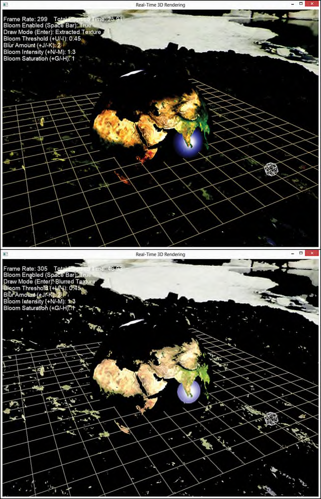
通过使用高斯模糊组件对glow map进行模糊处理,使得该glow map显示出了一种“流血”的效果就像光被其实的pixels吸收了一样。然后把模糊处理后的glow map与原始的scene texture结合得到最终的结果,但是你也可以使用强度(intensity)和饱和度(saturation)值进一步调整最终的scene颜色值。本书的配套网站上提供了一个示例程序,支持在运行时动态调整强度和饱和度值。通过使用不同的值将会生成一些有趣的结果。
Distortion Mapping
本章要讨论的最后一种post-processing technique是失真贴图(distortion mapping)。Distortion mapping类似于第9章“Normal Mapping and Displacement Mapping”所讲的移位贴图(displacement mapping) effect。但不同的是,displacement mapping是通过改一个object的vertices,而distortion mapping是改变pixels。更具体地说,就是首先经过纹理采样(一个distortion map)得到水平和垂直方向的偏移量,然后把这些偏移量用作在scene texture查找纹理的UV坐标。A Full-Screen Distortion Shader
列表18.13列出了一个full-screen post-processing distortion effect的pixel shader的代码。列表18.13 A Full-Screen Distortion Mapping Pixel Shader
cbuffer CBufferPerObjectComposite
{
	float DisplacementScale = 1.0f;
}

Texture2D SceneTexture;
Texture2D DistortionMap;

SamplerState TrilinearSampler
{
	Filter = MIN_MAG_MIP_LINEAR;
	AddressU = CLAMP;
	AddressV = CLAMP;
};

float4 displacement_pixel_shader(VS_OUTPUT IN) : SV_Target
{
	float4 OUT = (float4)0;
	float2 displacement = DistortionMap.Sample(TrilinearSampler, IN.TextureCoordinate).xy - 0.5;
	OUT = SceneTexture.Sample(TrilinearSampler, IN.TextureCoordinate + (DisplacementScale * displacement));
	return OUT;
}
在pixel shader中,通过采样两个通道值(x和y)得到displacement变量的水平和垂直方向值。这些通道值都是8-bit,由范围[0, 255]映射到浮点数范围[0.0, 1.0]。但是pixel的displacement值可以是正数也可以是负数,因此需要扩展这些范围。具体范围由所创建的displacement maps决定,但是在本书的这个例子中使用范围[-0.5, 0.5]。从一个美术设计师的角度看,通道值为127表示(almost几乎)不进行移位displacement。之所以说几乎(almost)不移位,是因为127 / 255 ≈ 0.49804,因此有一个0.5 - 0.49804 = 0.00196的误差值。通过在displaceent计算中加上该误差值,就可以抵销这个误差。例如:
static const float ZeroCorrection = 0.5f / 255.0f;
float2 displacement = DistortionMap.Sample(TrilinearSampler, IN.TextureCoordinate).xy - 0.5 + ZeroCorrection;
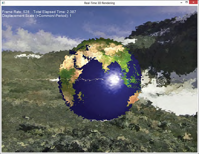
渲染这种distortion mapping shader与color filtering shadrs一样,就是一个正常的post-processing。首先把场景渲染到一个off-screen render target中,然后使用distortion mapping shader把一个full-screen quad渲染到back buffer中。图18.8显示了displacement shader的渲染输出结果,其中使用了一种看起来像毛玻璃效果的distortion map。
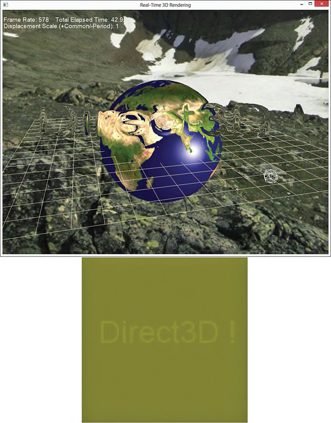
使用毛玻璃效果的distortion map所产生的变化是如此细微,以至于无法简单地区分失真的干扰(即使是在一个放大的图像中)。因此,在displacement shader中使用一种包含“Direct3D !”文字的distortion map(如图18.9下图所示),可以得到如图18.9上图所示的输出结果。该distortion map呈现出一种淡黄色,因为在该map中每一个pixel只填充了red和green通道值。
A Masking Distortion Shader
使用full-screen distortion mapping shader可以产生一些有趣的效果,如果动态处理displacenment偏移值(通过使用一个持续变化的值(如时间值)来调整该偏移值),则会使渲染结果更有趣。但是,我们可能并不想让整个场景都失真。例如,通过使图像局部失真可以模拟一团火焰上(或者发热的路面上)的烟雾,并在该特定区域独立使用这种effect。实现这种效果的一种方法是创建一个运行时的distortion mask(失真蒙板),在一个full-screen distortion map上裁剪一块将要进行失真处理的区域。图18.10显示了一个使用毛玻璃的失真贴图以及一个sphere创建的distortion mask。
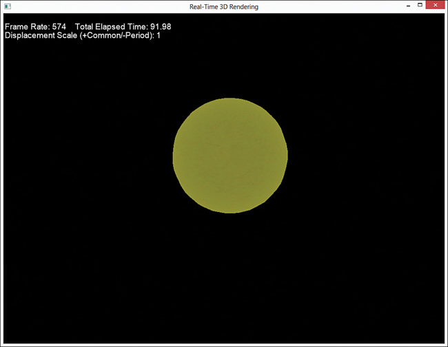
要创建这种distortion mask,需要在一个off-screen render target中首先ClearRenderTarget为黑色,然后渲染objects。但是,我们可以从一个distortion map中获取偏移值,而不是从一个object的color texture中采样颜色值。因此,在最终创建的distortion mask中要么是黑色的区域要么是distortion偏移值。创建完mask之后,就可以在scene texture和distortion mask之间执行post-processing操作。首先,从distortion mask中采样偏移值,如果该值表示黑色,那么采scene texture就不需要移位纹理的UV坐标。否则,就使用从mask中采样的偏移值对纹理的UV坐标进行偏移。列表18.14列出了distortion mapping effect的完整代码。
列表18.14 A Masking Distortion Mapping Effect
/************* Resources *************/
static const float ZeroCorrection = 0.5f / 255.0f;

cbuffer CBufferPerObjectCutout
{
    float4x4 WorldViewProjection : WORLDVIEWPROJECTION;
}

cbuffer CBufferPerObjectComposite
{
    float DisplacementScale = 1.0f;
}

Texture2D SceneTexture;
Texture2D DistortionMap;

SamplerState TrilinearSampler
{
    Filter = MIN_MAG_MIP_LINEAR;
    AddressU = CLAMP;
    AddressV = CLAMP;
};

/************* Data Structures *************/

struct VS_INPUT
{
    float4 Position : POSITION;
    float2 TextureCoordinate : TEXCOORD;
};

struct VS_OUTPUT
{
    float4 Position : SV_Position;
    float2 TextureCoordinate : TEXCOORD;
};

/************* Cutout *************/

VS_OUTPUT distortion_cutout_vertex_shader(VS_INPUT IN)
{
    VS_OUTPUT OUT = (VS_OUTPUT)0;

    OUT.Position = mul(IN.Position, WorldViewProjection);
    OUT.TextureCoordinate = IN.TextureCoordinate;

    return OUT;
}

float4 displacement_cutout_pixel_shader(VS_OUTPUT IN) : SV_Target
{
    float2 displacement = DistortionMap.Sample(TrilinearSampler, IN.TextureCoordinate).xy;

    return float4(displacement.xy, 0, 1);
}

/************* Compositing *************/

VS_OUTPUT distortion_composite_vertex_shader(VS_INPUT IN)
{
    VS_OUTPUT OUT = (VS_OUTPUT)0;

    OUT.Position = IN.Position;
    OUT.TextureCoordinate = IN.TextureCoordinate;

    return OUT;
}

float4 distortion_composite_pixel_shader(VS_OUTPUT IN) : SV_Target
{
    float4 OUT = (float4)0;

    float2 displacement = DistortionMap.Sample(TrilinearSampler, IN.TextureCoordinate).xy;
    if (displacement.x == 0 && displacement.y == 0)
    {
        OUT = SceneTexture.Sample(TrilinearSampler, IN.TextureCoordinate);
    }
    else
    {
        displacement -= 0.5f + ZeroCorrection;
        OUT = SceneTexture.Sample(TrilinearSampler, IN.TextureCoordinate + (DisplacementScale * displacement));
    }

    return OUT;
}

float4 no_distortion_pixel_shader(VS_OUTPUT IN) : SV_Target
{
    return SceneTexture.Sample(TrilinearSampler, IN.TextureCoordinate);
}

/************* Techniques *************/

technique11 displacement_cutout
{
    pass p0
    {
        SetVertexShader(CompileShader(vs_5_0, distortion_cutout_vertex_shader()));
        SetGeometryShader(NULL);
        SetPixelShader(CompileShader(ps_5_0, displacement_cutout_pixel_shader()));
    }
}

technique11 distortion_composite
{
    pass p0
    {
        SetVertexShader(CompileShader(vs_5_0, distortion_composite_vertex_shader()));
        SetGeometryShader(NULL);
        SetPixelShader(CompileShader(ps_5_0, distortion_composite_pixel_shader()));
    }
}

technique11 no_distortion
{
    pass p0
    {
        SetVertexShader(CompileShader(vs_5_0, distortion_composite_vertex_shader()));
        SetGeometryShader(NULL);
        SetPixelShader(CompileShader(ps_5_0, no_distortion_pixel_shader()));
    }
}
在该shader中包含了三种techniques: distortion_cutout:调用vertex和pixel shader用于创建distortion mask。在vertex shader中,输入参数的vertex position应该位于object space,因此需要对position执行变换。在pixel shader中,使用vertices的纹理坐标从distortion map采样颜色值,然后把x和y通道值作为输出。
distortion:定义了在scene texture和distortion map之间post-processing的执行步骤。在vertex shader中要求输入的vertex positions已经位于screen space,而且不执行变换(与所有的post-processing effects一样)。在pixel shader中根据采样得到的偏移值,判断在采样scene texture时是否要使用displacement偏移值。
no_distortion:不执行失真操作,直接输出scene texture。
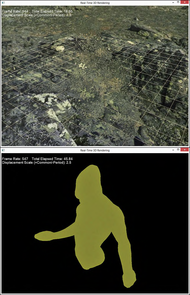
渲染masking distortion shader需要使用两个render targets,一个用于渲染无失真的背景objects,另一个用于创建distortion mask。在本书的配套网站上提供一个完整示例程序。图18.11中显示了使用masking distortion shader的输出结果(上图),该shader中使用了一种人形躯干模型创建distortion mask(下图)。
总结
本章介绍了post-processing主题相关的知识,post-processing是指在渲染完成后的场景中使用一些图形技术。编写了大量的post-processing effects用于表示color filtering,Gaussian blurring,bloom/glow以及distortion mapping。并在C++渲染引擎中使用full-screen render target和quad component集成了这些effects,最后通过演示程序练习了这些effects的使用。在下一章,我们将会学习projective texture mapping(投影纹理贴图)和shadow mapping(阴影贴图)。
Exercises
1. Experiment with all the effects and demo applications from this chapter. Vary the shaderinputs, and observe the results.
2. Create your own distortion maps for the post-processing distortion shader, and use them
with the associated demo application.
3. Animate the masking distortion shader to simulate heat haze above a fire. Hint: Use
GameTime::TotalGameTime() as input into the shader.
1、测试本章所有的effect和示例程序。在shader中使用不同的输入,并观察输了结果。
2、创建你自己的distortion maps用于post-processing distortion shader,并在对应的示例程序中使用该shader。
3、实现一个动态变化的masking distortion shader,用于模拟一团火焰上的烟雾效果。提示:使用函数GameTime::TotalGameTime()的返回值作为shader的输入。


 2万+
2万+


 被折叠的 条评论
为什么被折叠?
被折叠的 条评论
为什么被折叠?
 到【灌水乐园】发言


