


1,色散在光学中的原理
2,反射的原理以及环境映射的实现
3,折射的原理以及色散的实现
4,菲涅尔效果
5,将菲涅尔与色散效果增加到环境映射中
1,色散在光学中的原理
复色光
——现实生活中的许多光都是复色光,例如阳光。
光谱
——光学频谱,简称光谱,是复色光通过色散系统(如光栅、棱镜)进行分光后,依照光的波长(或频率)的大小顺次排列形成的图案。
https://zh.wikipedia.org/wiki/%E5%85%89%E5%AD%B8%E9%A0%BB%E8%AD%9C
色散
——复色光通过介质产生折射时,由于各个通过复色光中各个光的波长不同而导致的折射率不同所产生各个光线依次分开。
2,反射的原理以及环境映射的实现
反射可以用来解释你在镜子或水面中看到的景象。将你看向镜面的视角抽象为一组向量,当这组向量接触到镜面后会生成一组反射向量,而这组反射向量再次接触到的点的集合既是你在镜面中所见的景象。
二维中看起来比较简单,w为入射向量,r为反射向量,S为反射介质,P为反射点,n垂直于S。只要做到w与s的夹角与r与s的夹角相等,既做到了反射。
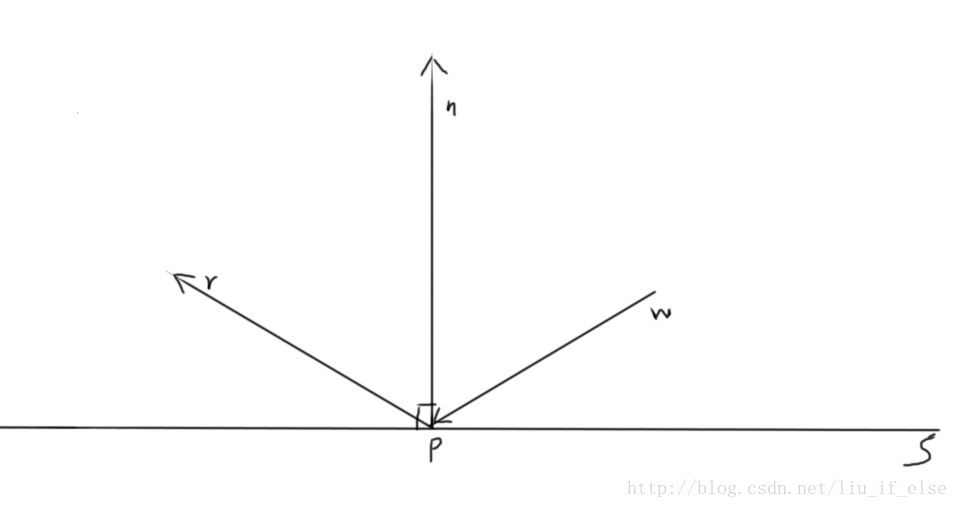
但在三维中,是通过一系列向量运算来寻找反射向量的。
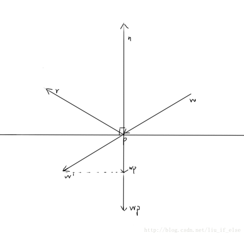
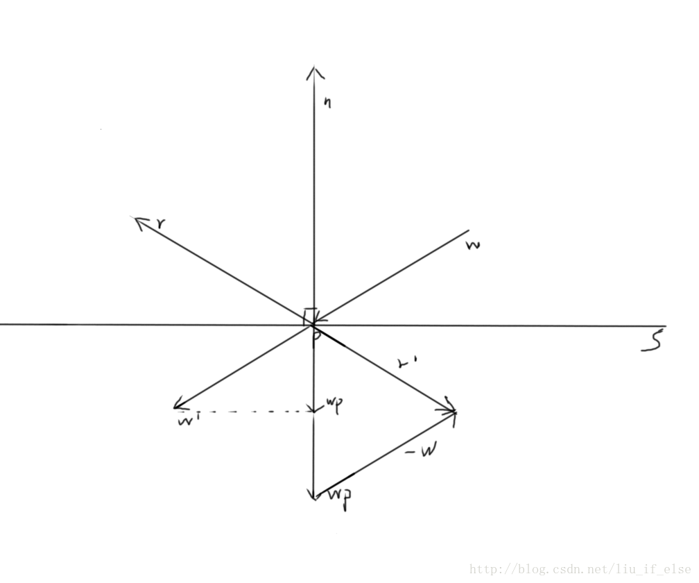
首先计算w的projection,并移到下方。视觉上理解既是将w移到w’处,n向下延伸,从w’做一条垂直于n的虚线,n的延伸与虚线的交点既是向量wp的终点,wp=dot(w,n/|n|),然后再做一条wp。在wp*2的终点画一条’-w’,根据向量的加法法则,r’=wp*2-w, -r’=r既是w的反射向量。
用数学公式表达则是:
wp=dot(w,n/|n|) , wp is the projection of w on n.
r’=wp*2-w
r=-r’ ,w的反射向量
而在Shader中,以上这些都被简化成了一个方法:
- 1
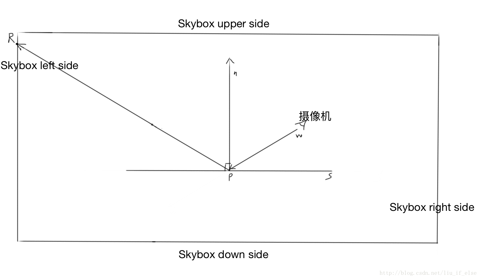
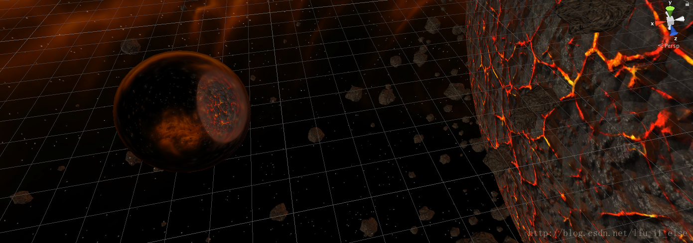
环境映射既是利用反射对天空盒进行立方体采样,模拟现实中的镜像。
摄像机在镜面S上所见的景象为Skybox左边的点R。
以下代码为Unity官网的环境映射示例Shader。将插值与计算部分移到了片段着色器中,以优化显示效果。
- 1
- 2
- 3
- 4
- 5
- 6
- 7
- 8
- 9
- 10
- 11
- 12
- 13
- 14
- 15
- 16
- 17
- 18
- 19
- 20
- 21
- 22
- 23
- 24
- 25
- 26
- 27
- 28
- 29
- 30
- 31
- 32
- 33
- 34
- 35
- 36
- 37
- 38
- 39
- 40
- 41
- 42
- 43
- 44
- 45
- 46
- 47
- 48
- 49
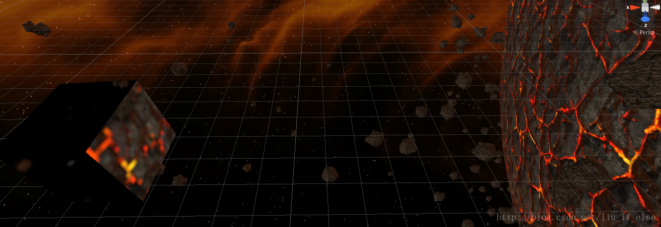
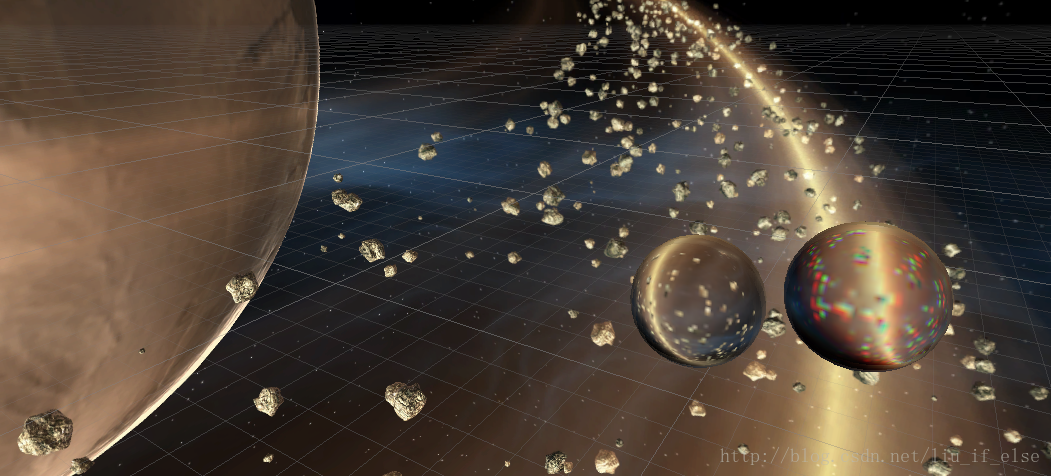
效果:
这里进一步解释一下,当利用反射进行环境映射时,有弧度的物体的效果要明显优于平面物体,因为有弧度的平面生成的反射向量角度更广,在进行立方体采样时模拟出的距离感更加真实。而由于天空盒与场景中的物体距离是有限的(而且其实并不是很远), 平面物体生成的反射向量大部分都反射到了天空盒的一侧的小部分区域,效果很失真,实际是由于这种反射”揭穿”了天空盒虚拟出的的无限远效果。
上图中立方体反射出星球的一小块区域。
3,折射的原理以及色散的实现
折射可以解释透过玻璃所看到的扭曲的景象。
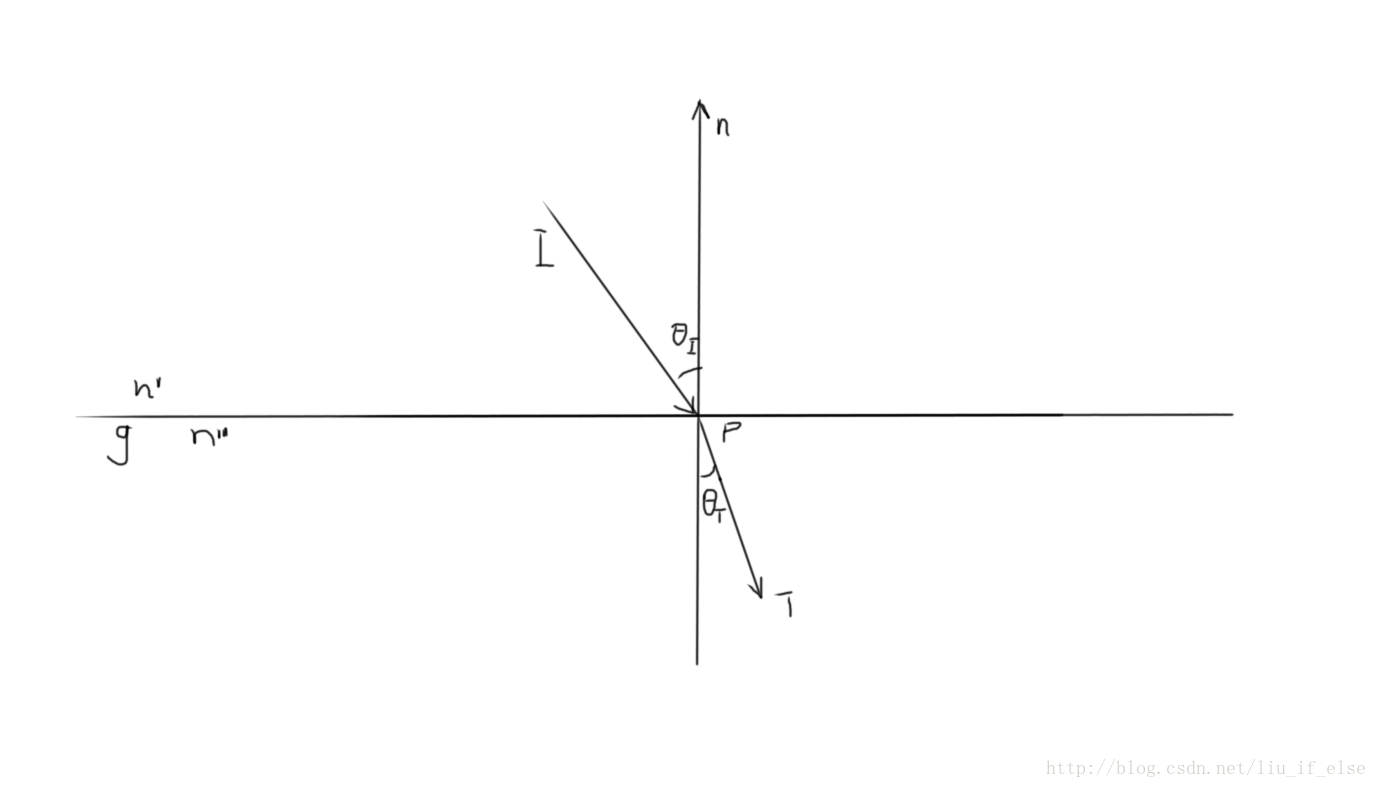
假设g为玻璃,空气的折射率为n’,玻璃的折射率为n”
当入射向量接触到介质g后,根据折射率n’与n”的差别,它的前行方向将会发生变化。
这种变化可用斯涅耳定律来进行计算:
snell’s law:
n′sinθi=n′′sinθT
在Shader中,折射的计算也被简化成了一个方法:
- 1
其中etaRatio=n’/n”。
各种介质的etaRatio一览:
————————————————
真空:1.0
水:1.3333
玻璃:1.5
钻石:2.417
水晶: 1.544-1.553
————————————————
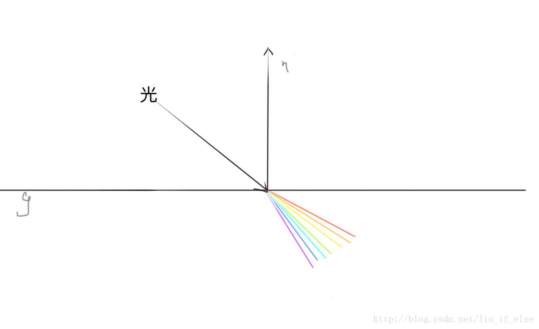
色散的实现:
最上面解释过:复色光通过介质产生折射时,由于各个通过复色光中各个光的波长不同而导致的折射率不同所产生各个光线依次分开。
所以首先看下复色光中各个光的波长:
——————————
红:620-750nm
橙:590nm
黄:570nm
绿:495nm
青:450nm
蓝:420nm
紫:380nm
——————————
而由于折射率是取决于波长的,所以折射出的各个颜色的光的顺序是一致的。
代码,这里只用红绿蓝做示例:
先将折射率计算好,存在etaRatio的x,y,z中。
- 1
- 2
- 3
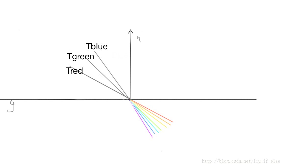
算出折射后的向量,分别进行立方体采样,并只取相应的颜色。
- 1
- 2
- 3
- 4
- 5
refractedColor既是在环境映射中模拟出的介质后方景象产生色散的效果。
实际是在环境映射的过程中偏移采样角度反向的模拟出色散。Tblue,Tgreen,Tred既是上面反射采样中的r,而入射角实际是在g的下方。
4,菲涅尔效果
意义:
当光从一种具有折射率为的介质向另一种具有折射率为的介质传播时,在两者的交界处(通常称作界面)可能会同时发生光的反射和折射。菲涅尔方程描述了不同光波分量被折射和反射的情况。
https://zh.wikipedia.org/wiki/%E8%8F%B2%E6%B6%85%E8%80%B3%E6%96%B9%E7%A8%8B
这个没能力具体的好好解释了。总之有一个公式在shader里可以使用,返回值将用于最终的反射颜色与折射颜色的lerp混合中。
公式中的fresnelBias,fresnelScale与fresnelPower的赋值将会影响最终效果,如何赋值的原理没找到。我在下面的例子中赋值的power=4,scale=0.1,bias=-0.2。试验中发现将返回值的可能范围尽量精确至0-1效果最佳。
- 1
5,将菲涅尔与色散效果增加到环境映射中
综合以上写一个Shader:
- 1
- 2
- 3
- 4
- 5
- 6
- 7
- 8
- 9
- 10
- 11
- 12
- 13
- 14
- 15
- 16
- 17
- 18
- 19
- 20
- 21
- 22
- 23
- 24
- 25
- 26
- 27
- 28
- 29
- 30
- 31
- 32
- 33
- 34
- 35
- 36
- 37
- 38
- 39
- 40
- 41
- 42
- 43
- 44
- 45
- 46
- 47
- 48
- 49
- 50
- 51
- 52
- 53
- 54
- 55
- 56
- 57
- 58
- 59
- 60
- 61
- 62
- 63
- 64
- 65
- 66
- 67
- 68
- 69
- 70
- 71
- 72
- 73
- 74
- 75
- 76
- 77
- 78
- 79
- 80
- 81
- 82
- 83
- 84
- 85
- 86
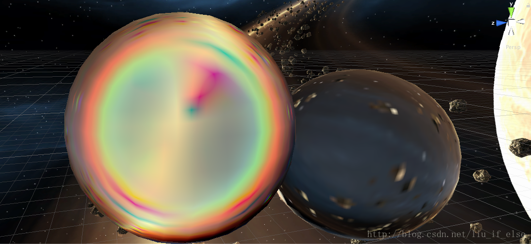
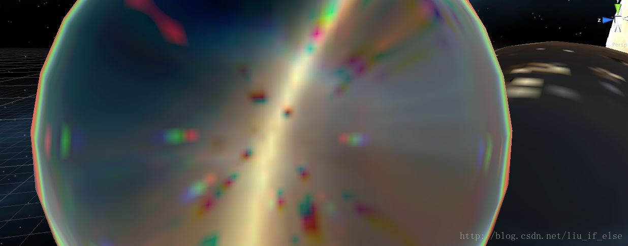
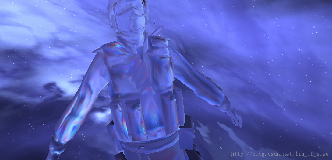
效果:
上图中一个玻璃球使用普通折射Shader,一个使用菲涅尔色散Shader。
加在一个人形模型上。
利用此Shader表现的晶体材质更加真实。
——————————————————————————————————
参考资料:
Cg Tutorial–Nvidia
维基百科
https://en.wikipedia.org/wiki/Chromatic_aberration
百度百科
http://baike.baidu.com/link?url=mfGv-8-d_GLdSBfpzsxV38M9ugwIxgbTlEe6neAQziOMVLuJ27_ZM7y0TKNYMbiknrE9aN8qW2ZTGD0pMRJ1bkyYEP_z_u2cNu3kbulXMQu


 1697
1697

 被折叠的 条评论
为什么被折叠?
被折叠的 条评论
为什么被折叠?
 到【灌水乐园】发言


