


来源:https://www.cnblogs.com/chengqi521/p/7867066.html、https://blog.csdn.net/qq_22279697/article/details/80763018、https://blog.csdn.net/hhpingyear/article/details/96750849
1.Ibert回环测试问题
2.IBERT回环测试near-end-pcs误码率比near-end-pma误码率更高的问题。
AR# 53107 7 Series GTX/GTH Transceivers - Recommended usage in Near End PCS loopback mode
Description
This answer record provides guidelines to use 7 series GTX/GTH transceivers in PCS loopback mode.
Solution
In PCS loopback mode, if there is no connection from TXP/TXN to RXP/RXN, then RXRECCLK output from CDR is not expected to be good.
This is due to a lack of data transitions at the input to lock to.
If a design requires RXRECCLK for its fabric logic, the design can fail.
For these designs, it is recommended to use CDR in “lock to reference” mode.
Follow the steps below to make sure that the CDR is in “lock to reference” mode:
Step1: Drive the following signals
Set RXOUTCLKSEL to select RXOUTCLKPCS,
(OR)
Set RXCDRHOLD to 1’b1 and RXCDROVRDEN to 1’b0
Step2: Perform a full RX reset of the transceiver
Pulse GTRXRESET
If a design does not use RXRECCLK for fabric logic, only Step 2 is required.
AR# 34203 11.x ChipScope - IBERT - Spartan-6, Virtex-5, Virtex-6 - PCS loopback results in an increasing error count
Description
When I set my GT to near-end PCS loopback, I see the bit error rate increasing. Is there an issue with my device?
Solution
This is a result of clock settings in the core. As a work-around, use PMA near-end loopback. Alternatively, you canchange the Loopback mode to Near-End PMA and then change back to Near-End PCS. Reset Error count and note that no errors occur.
1.FAR-END-PCS和far-end-pma测试软件界面设置问题。
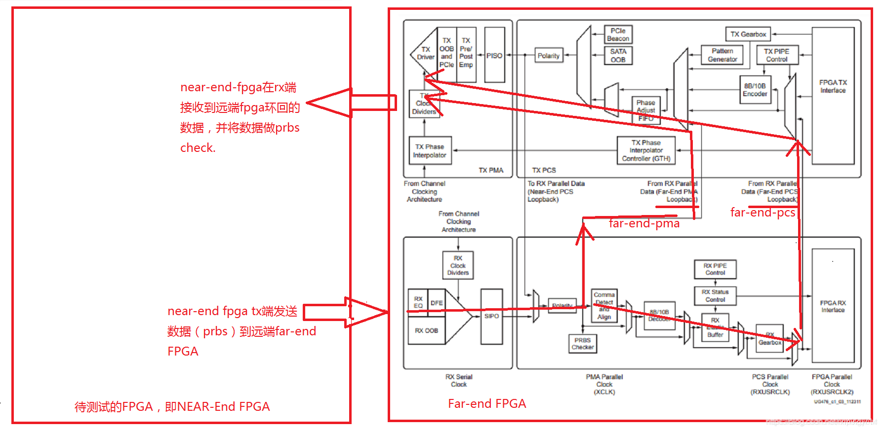
因此,
1.左边FPGA RX端观测far-end-pma时,左边FPGA设置为none模式,这时候信号从左边FPGA tx pin端口发送到右边FPGA,在右边FPGA中设置为far-end-pma.
2.左边FPGA RX端观测far-end-pcs时,左边FPGA设置为none模式,这时候信号从左边FPGA tx pin端口发送到右边FPGA,在右边FPGA中设置为far-end-pcs.
3.如果右边不是fpga,比如一个光纤或是背板时,左边设置为none,右边就外部直接回环了。
2. Ibert测试vivado与ISE异同问题。
对于IBERT测试时,NEAR-END-PCS误码率比near-end-pma误码率高问题,提到的rxusrclk的时钟设置方法。其中在ISE下面ibert有可设置的DRP界面,但是VIVADO下面已经没有了。
HTG813与HTG814相关问题
注意HTG813是48路光路TX,而HTG814是48路光路RX,当他们直接相连进行外部回环ibert测试时,光路TX1对应光路RX12,而非TX1对应RX1.
———————————————
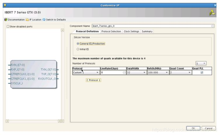
第一部分 生成IBERT IP及运行工程生成配置文件
1. 选择IP,选择FPGA版本,protocol数量 (所有通道用一个速率的话一般只选择1个 protocol),速率,参考时钟频率,通道数量和Quad PLL(大于6G的速率时必须选择)
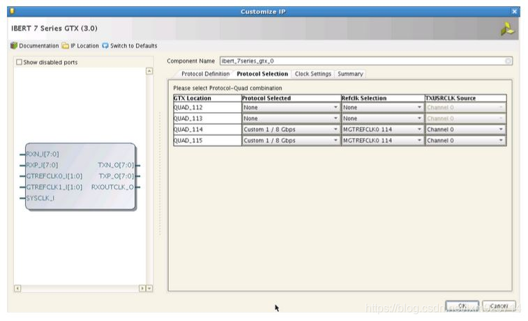
2. 选择需要的Quad 通道114和115,及参考时钟源,这里选择合用QUAD114的参考时钟
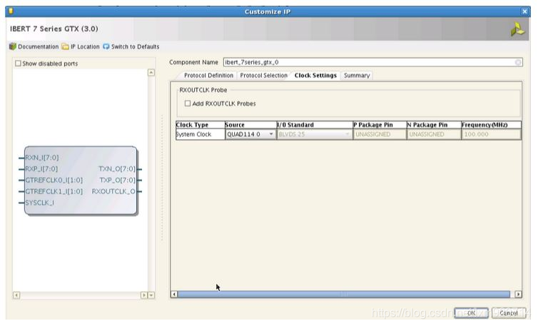
3.时钟源选择QUAD_114_CLK0做为整个IP的系统时钟,当然这个需要根据硬件实际情况来选择。
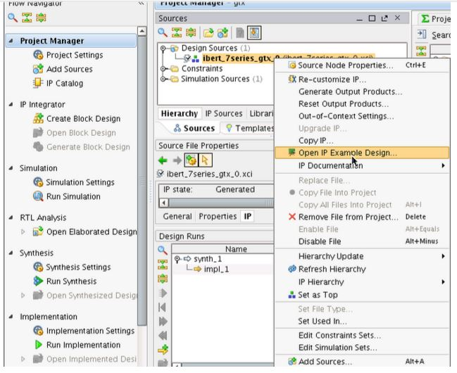
4.生成IP之后在IP的顶层右键点击Open IP Example Design,然后会打开一个新的VIVADO界面。
第二部分 上板利用IBERT验证GTX管脚
5.如果需要在ISE的ChipScope中查看IBERT时,直接点击ISE的ChipScope的Analyzer,然后点击链接->配置FPGA。如下图所示
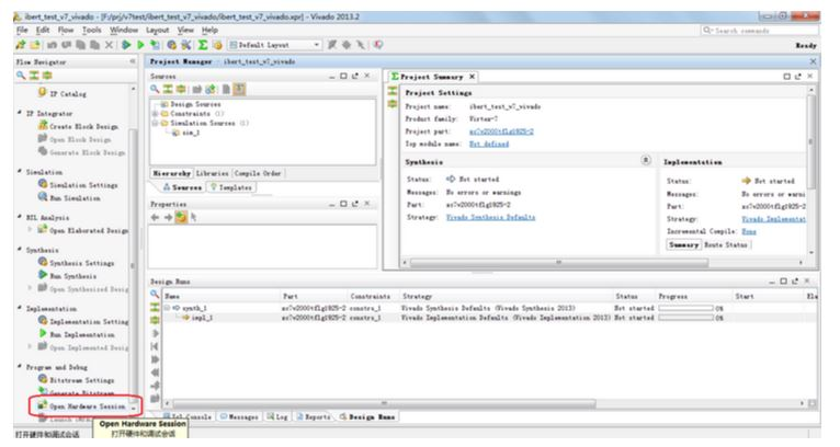
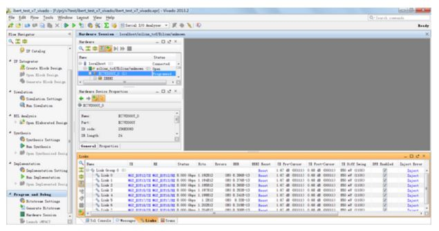
6.如果是要在Vivado中查看Ibert,则需要打开Hard ware Session,如下图所示
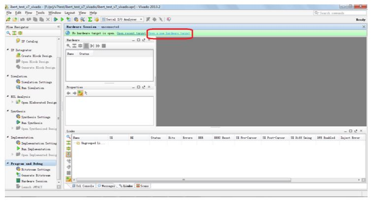
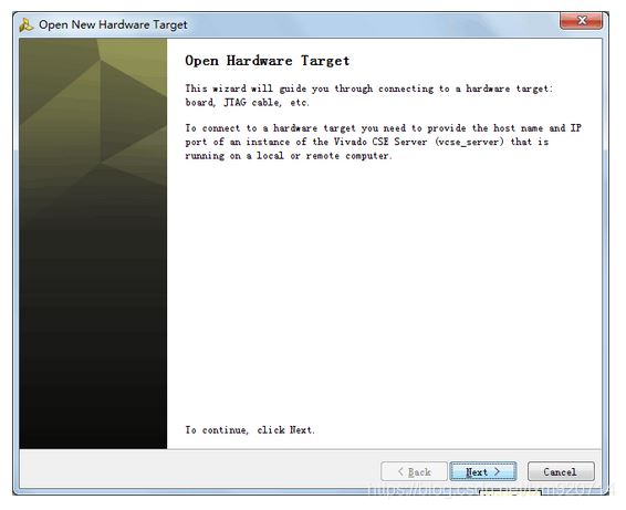
7. 点击Open a new hardware target
8. Open a new hardware target界面点击Next
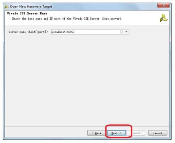
9. 不用更改,点击next
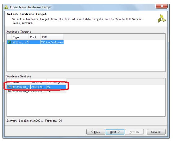
10.选择目标FPGA芯片点击next
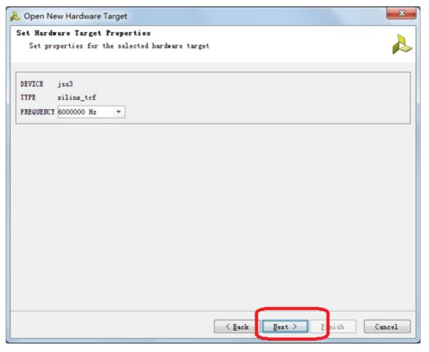
11.无需更改,点击next
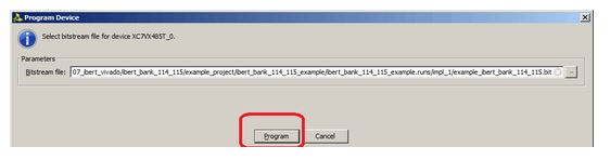
12. 选择配置文件
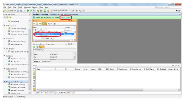
13.选择配置的FPGA,点击右上角create links
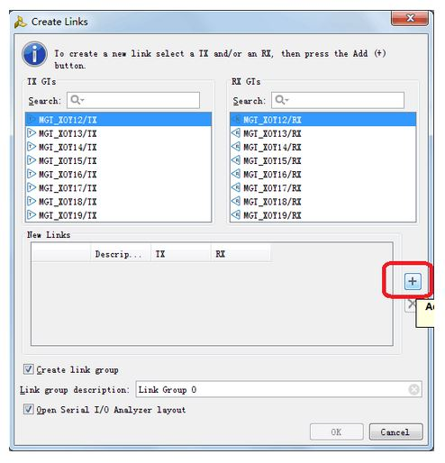
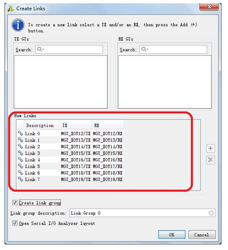
14.点击+号将所有通路添加进去
15. 点击Next
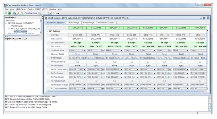
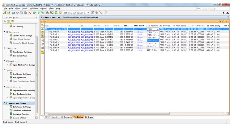
16. IBERT 界面
17.可将光标放在BERT栏上右键,就可以弹出菜单,根据需要添加或减去功能

18.将TX Pattern 和RX Pattern选为31 bit与IP中设置相符
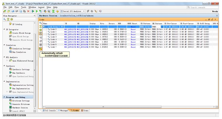
19. 点击AUTO REFRSSH可以看到各个通道的速率变化
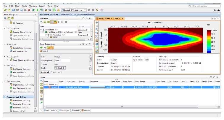
20. 选择一路通道,右键选择create scan可以创建眼图。
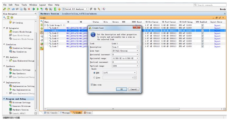
21.眼图


 1287
1287

 被折叠的 条评论
为什么被折叠?
被折叠的 条评论
为什么被折叠?
 到【灌水乐园】发言


