


 本文介绍了电子电路中的基本元件——电容和电感。电容的概念基于电荷与电压的关系,其电流电压关系体现在阻抗上,而电感则通过电磁感应来反对电流变化,遵循楞次定律。电感的品质因素(Q因子)衡量了其效率,高Q电感常用于共振电路。电容和电感在串联和并联电路中有不同的表现,并且在LC谐振电路中起着关键作用,用于信号的选择和生成。
all taken from Wikipedia
RC
https://en.wikipedia.org/wiki/RC_circuit
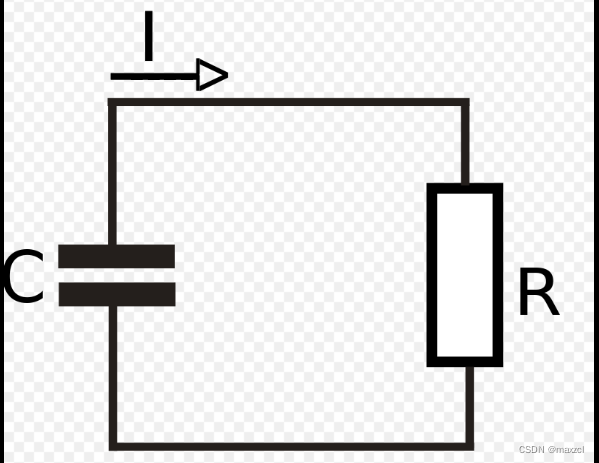
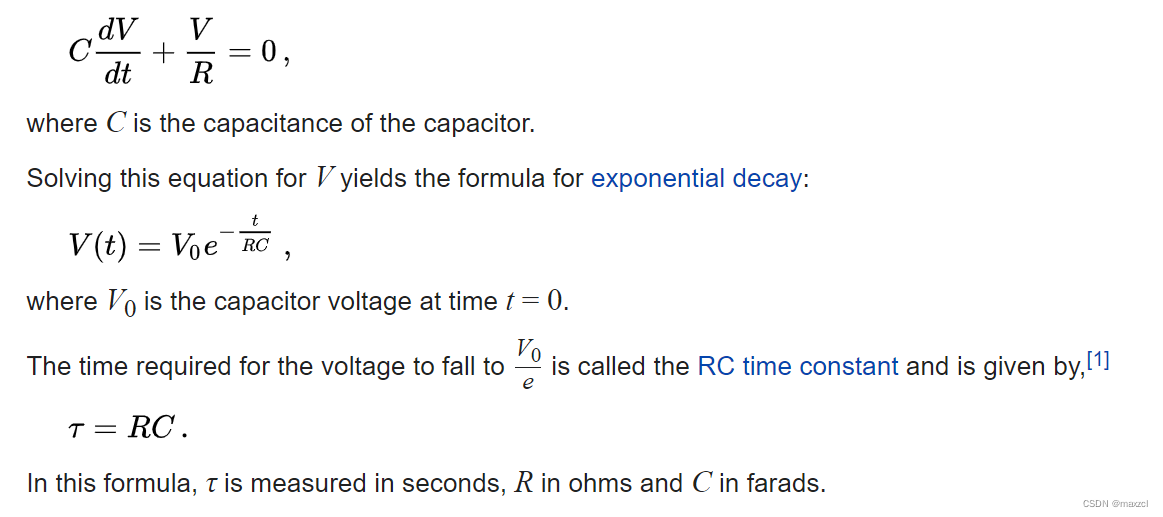
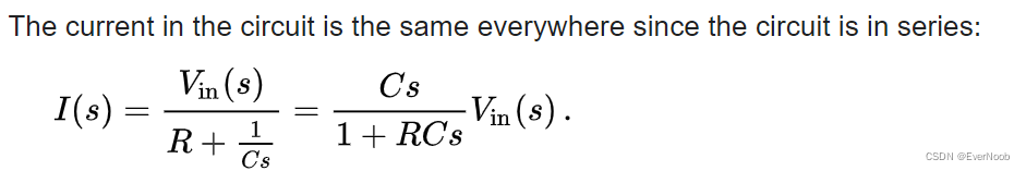
using Kirchhoff's current law
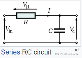
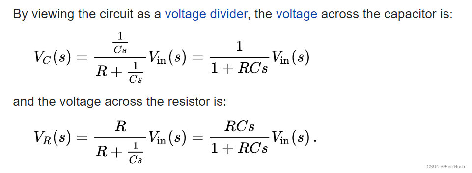
Series Circuit
 here we exploit reactance/impedance, see later in capacitor section.
s is for "second", since Q = I * t, C = Q/V ==> 1/C ~ Ohm/second
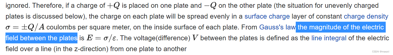
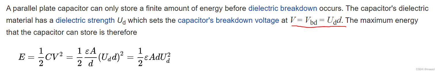
Capacitor
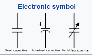
https://en.wikipedia.org/wiki/Capacitor
conceptually:
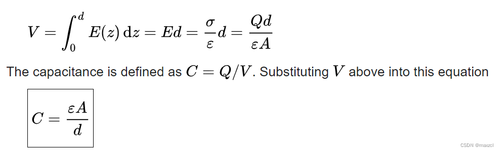
C = Q / V
or
C = dQ / dV
A capacitance of one farad (F) means that one coulomb of charge on each conductor causes a voltage of one volt across the device.[23]
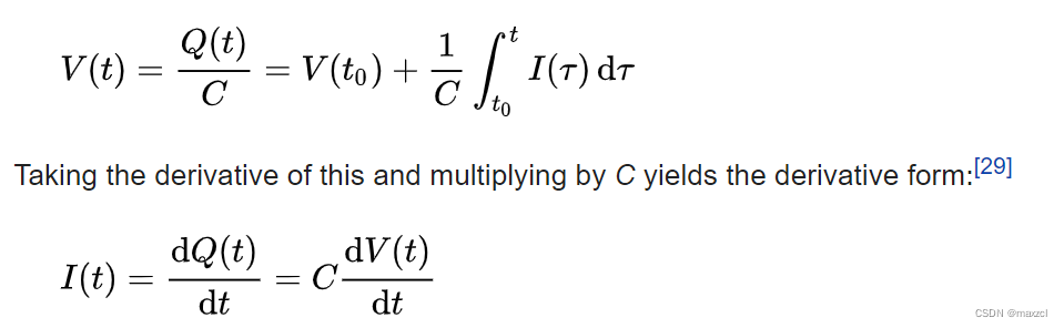
Current Voltage Relation
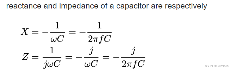
Impedance
Impedance, the vector sum of reactance and resistance, describes the phase difference and the ratio of amplitudes between sinusoidally varying voltage and sinusoidally varying current at a given frequency. Fourier analysis allows any signal to be constructed from a spectrum of frequencies, whence the circuit's reaction to the various frequencies may be found. The reactance and impedance of a capacitor are respectively:
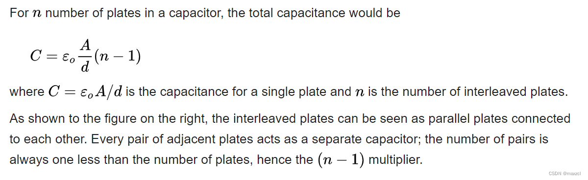
Interleaved Capacitors
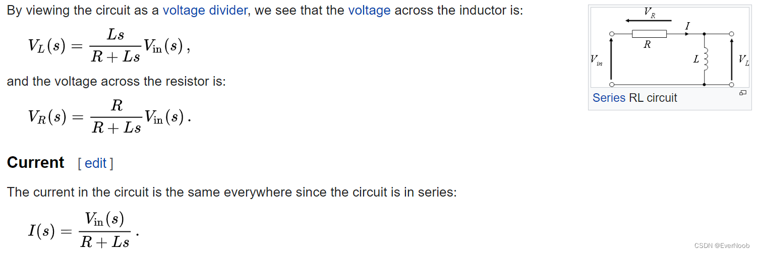
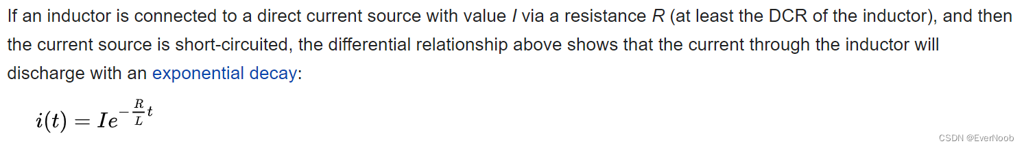
RL
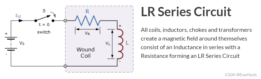
source: https://www.electronics-tutorials.ws/inductor/lr-circuits.html
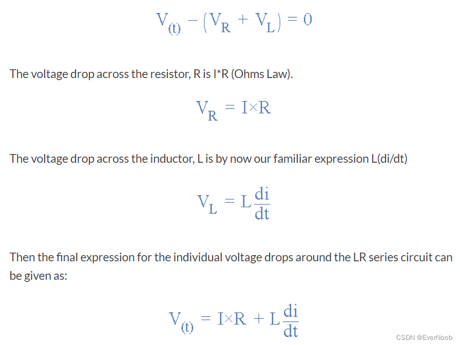
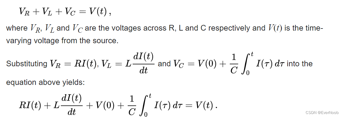
Kirchhoff’s voltage law (KVL) gives us:
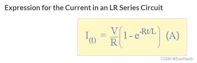
 ==> I can be thought of as the current in steady state, i.e. ignore contribution of R to I(t)
the detail on Inductor can be seen afterwards.
https://en.wikipedia.org/wiki/RL_circuit
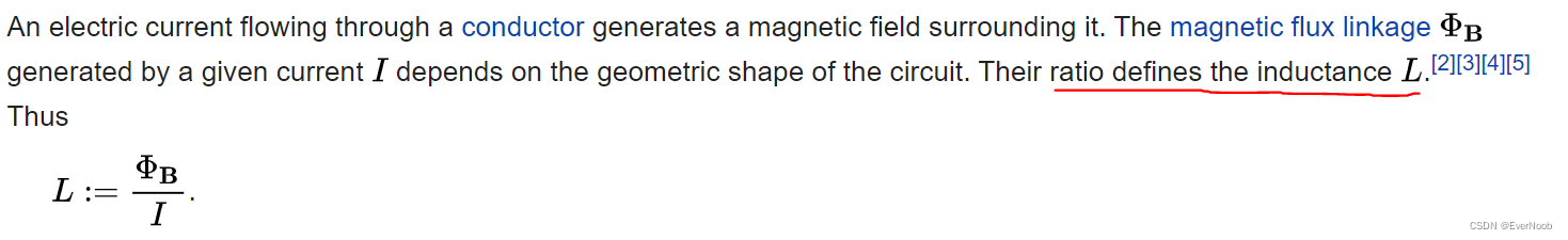
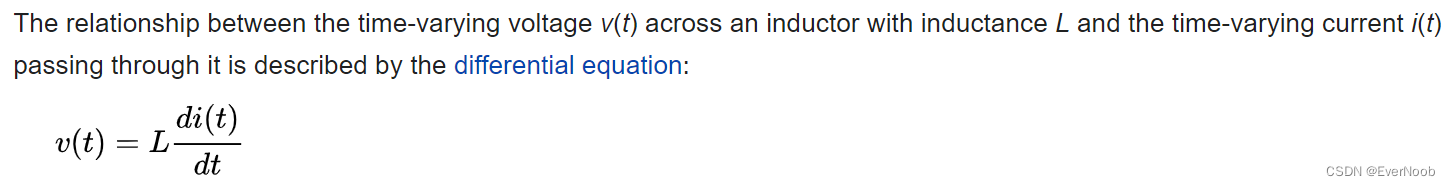
Inductor
https://en.wikipedia.org/wiki/Inductor
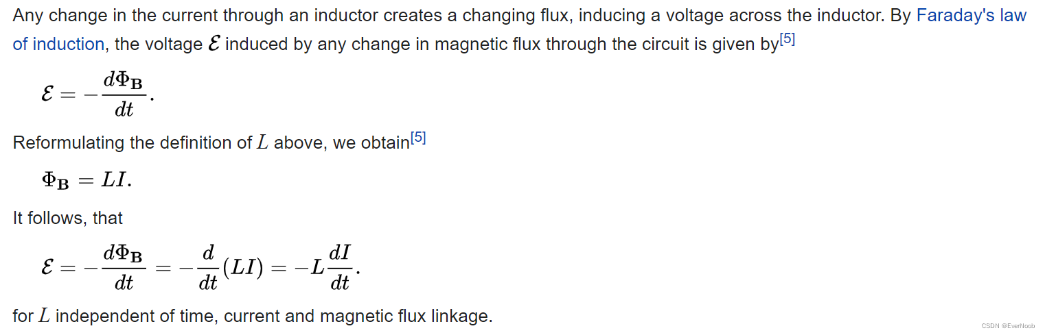
==> notably the voltage is misnamed as Electro-Motive "Force"
The polarity (direction) of the induced voltage is given by Lenz's law, which states that the induced voltage will be such as to oppose the change in current.[6]
Device Analysis
The effect of an inductor in a circuit is to oppose changes in current through it by developing a voltage across it proportional to the rate of change of the current. An ideal inductor would offer no resistance to a constant direct current; however, only superconducting inductors have truly zero electrical resistance.
according to the non-ideal assertion above, the common case DE should be a little more complicated as:
v(t) - EMF(t) - R*I(t) = 0
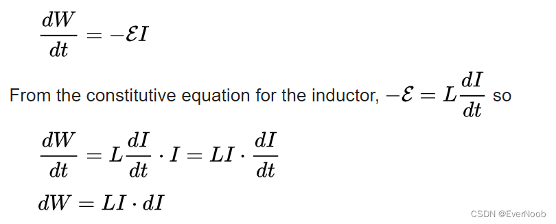
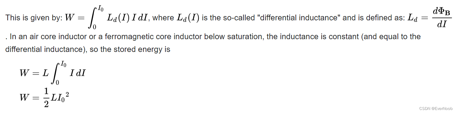
Energy Stored in an Inductor

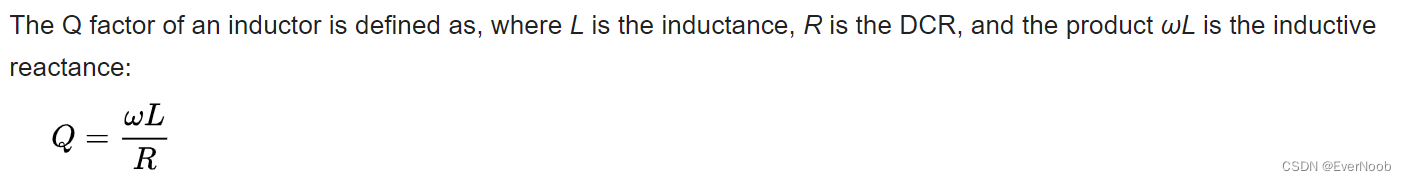
Q Factor
The winding resistance appears as a resistance in series with the inductor; it is referred to as DCR (DC resistance). This resistance dissipates some of the reactive energy. The quality factor (or Q) of an inductor is the ratio of its inductive reactance to its resistance at a given frequency, and is a measure of its efficiency. The higher the Q factor of the inductor, the closer it approaches the behavior of an ideal inductor. High Q inductors are used with capacitors to make resonant circuits in radio transmitters and receivers. The higher the Q is, the narrower the bandwidth of the resonant circuit.
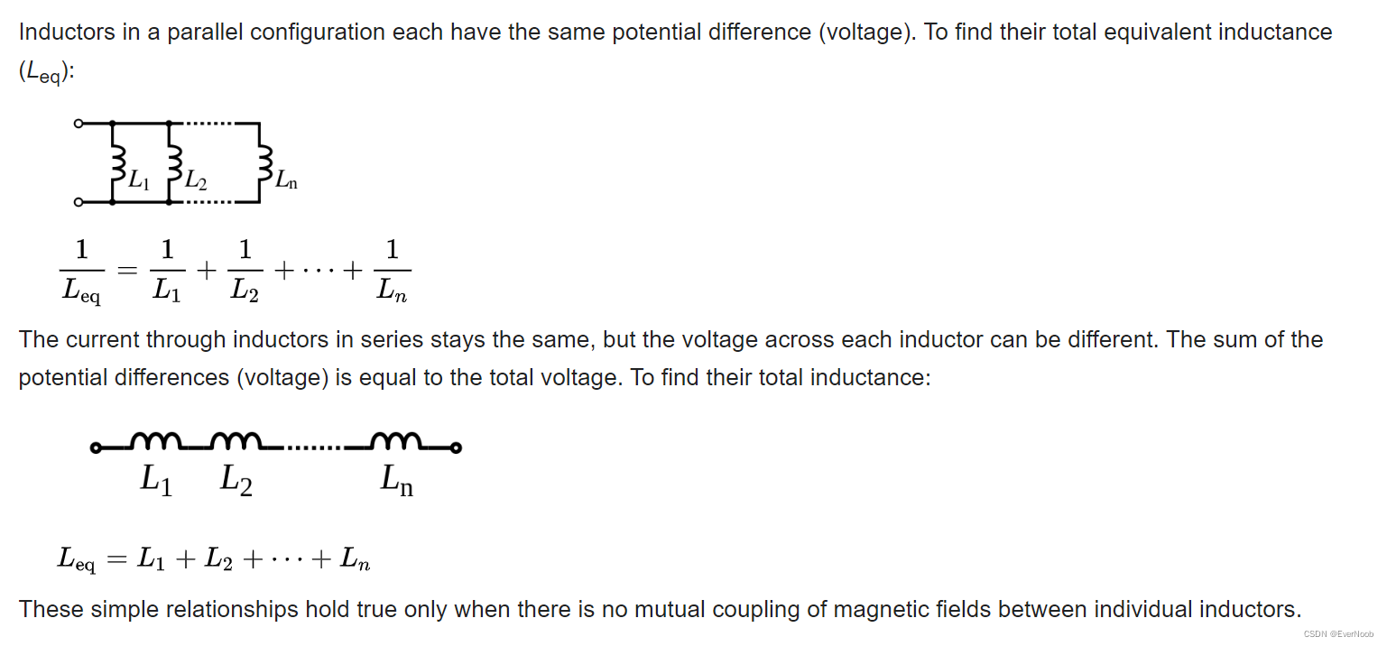
Parallel and Serial Inductors
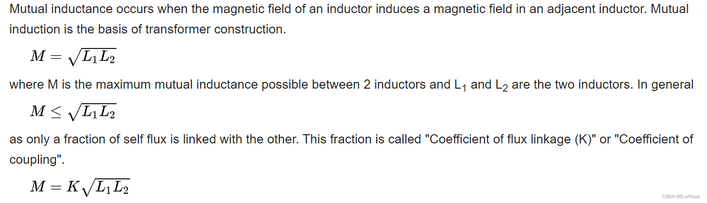
Mutual Inductance
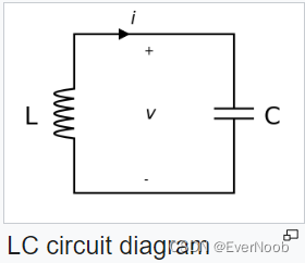
LC and RLC
https://en.wikipedia.org/wiki/LC_circuit
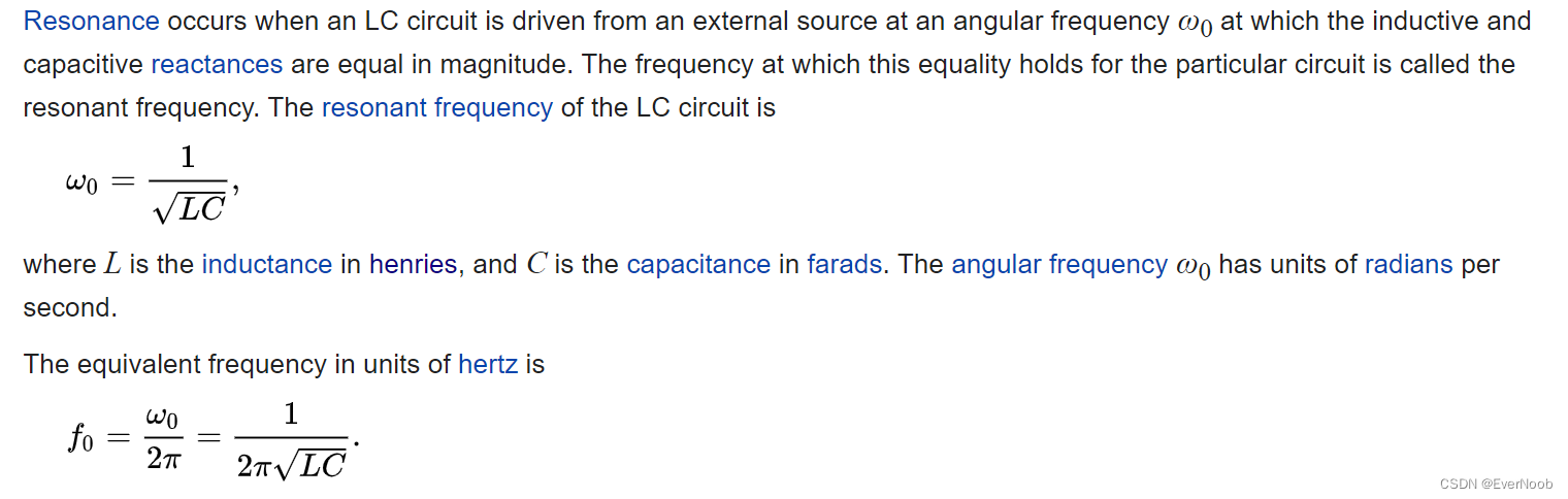
LC circuits are used either for generating signals at a particular frequency, or picking out a signal at a particular frequency from a more complex signal; this function is called a bandpass filter. They are key components in many electronic devices, particularly radio equipment, used in circuits such as oscillators, filters, tuners and frequency mixers.
An LC circuit is an idealized model since it assumes there is no dissipation of energy due to resistance. Any practical implementation of an LC circuit will always include loss resulting from small but non-zero resistance within the components and connecting wires. The purpose of an LC circuit is usually to oscillate with minimal damping, so the resistance is made as low as possible. While no practical circuit is without losses, it is nonetheless instructive to study this ideal form of the circuit to gain understanding and physical intuition. For a circuit model incorporating resistance, see RLC circuit.
LC Resonance Frequency (Serial LC)
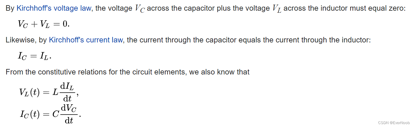
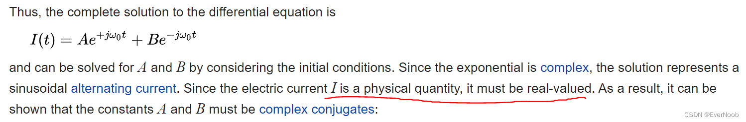
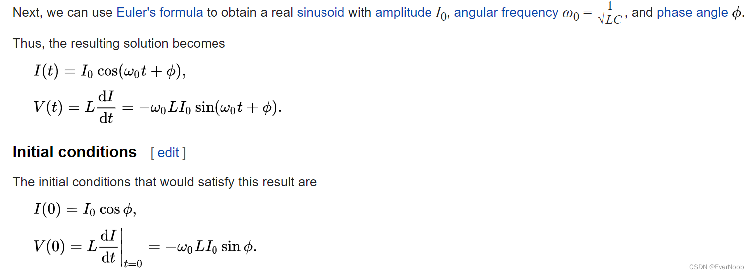
Derivation
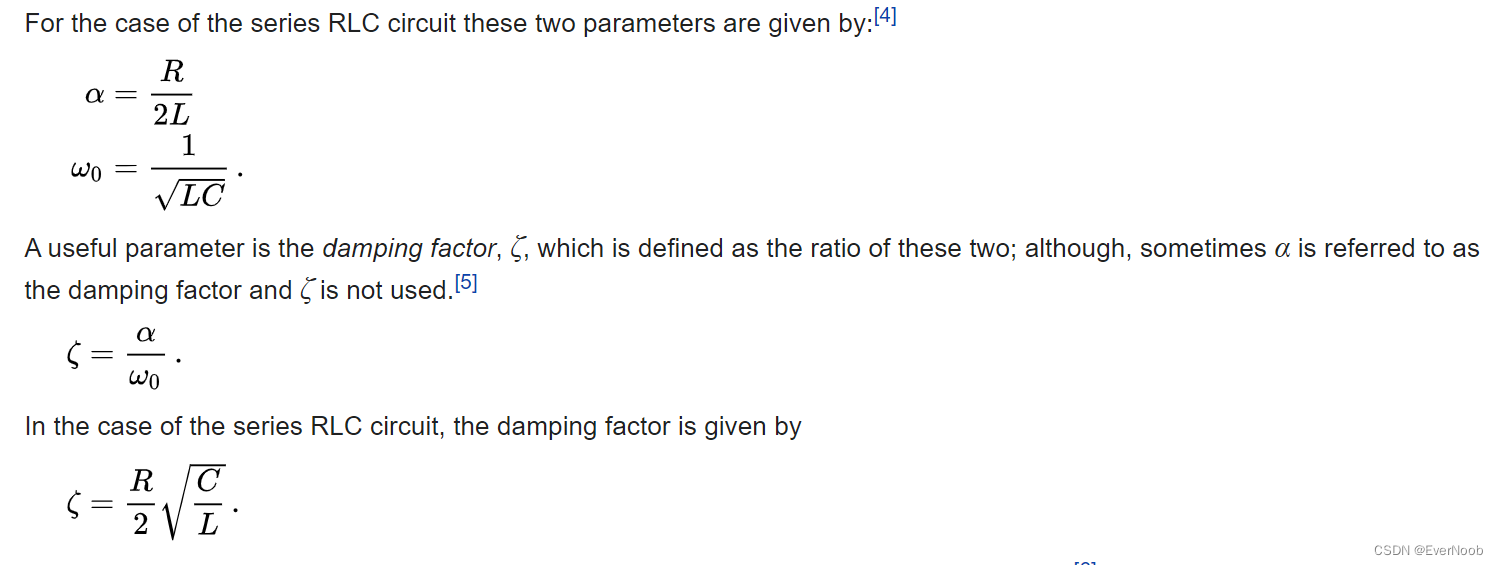
Serial RLC
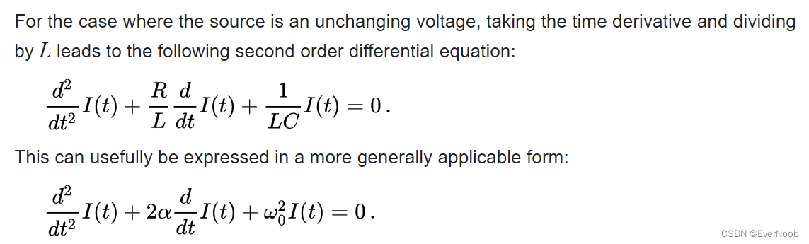
==> there are 3 major cases of damping, which is skipped here, but do checkout wiki for further details


 3435
3435

 被折叠的 条评论
为什么被折叠?
被折叠的 条评论
为什么被折叠?
 到【灌水乐园】发言


