


在上篇教程中,我们已经小有成就。我们用gizmos画出了密密麻麻的正方体来展示整个地图。
现在想象一下,我们把每个正方体缩小为一个点,就会出现下面的情况:
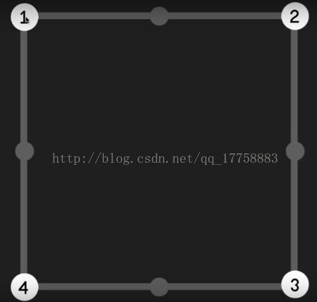
每个点有两种状态:0和1,分别代表道路和障碍,我们把这四个点当成一个二进制数字0000。
当它们全部是1的时候,也就是1111=15。如图:
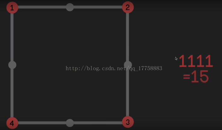
那我们可以得到的信息就是这四个点的组合方式有16种。每一种组合对应一种网格(mesh),而网格是由三角形组成的,下面是几个示例:
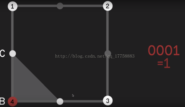
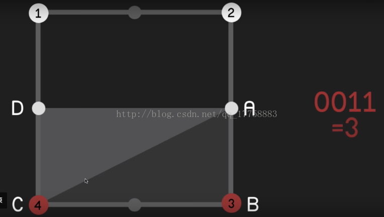
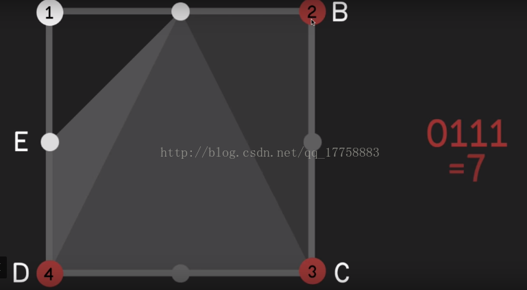
可以观察到的是,除了四个顶点,边的中点也用来组成网格。我们在这里定义顶点为控制节点,边的中点为节点。每个控制节点拥有两个节点:上方节点和右方节点。
下面我们来定义它们的数据结构,新建一个脚本命名为MeshGenerator:
    public class Node
    {
        public Vector3 position;
        public int vertexIndex = -1;	//顶点索引,我们以后将会用到

        public Node(Vector3 _pos)	//节点的构造函数,需要传入它的位置
        {
            position = _pos;
        }
    }
public class ControlNode : Node
{
public bool isActive; //控制节点是否激活
public Node above, right; //每个控制节点拥有两个节点
public ControlNode(bool _isActive, Vector3 _pos, int squareSize)
: base(_pos) //从父类构造函数传入位置,squareSize为四个控制节点形成的矩形的边长
{
isActive = _isActive;
above = new Node(position + Vector3.forward * squareSize / 2f);
right = new Node(position + Vector3.right * squareSize / 2f);
}
} public class Square
{
public ControlNode topLeft, topRight, bottomLeft, bottomRight; //一个矩形拥有四个控制节点
public Node centerTop, centerLeft, centerRight, centerBottom; //还有四个节点
public Square(ControlNode _topLeft, ControlNode _topRight, ControlNode _bottomLeft, ControlNode _bottomRight) //我们只需要定义四个控制节点
{
topLeft = _topLeft;
topRight = _topRight;
bottomLeft = _bottomLeft;
bottomRight = _bottomRight;
//控制节点包含节点
centerTop = topLeft.right;
centerBottom = bottomLeft.right;
centerLeft = bottomLeft.above;
centerRight = bottomRight.above;
}
} public class SquareGrid
{
public Square[,] squares; //代表了整张网格的信息
public SquareGrid(int[,] map, int squareSize) //构造函数传入Map数组信息和单个矩形的边长
{
int nodeCountX = map.GetLength(0); //X方向上节点的数量
int nodeCountY = map.GetLength(1); //Y方向上节点的数量
float mapWidth = nodeCountX * squareSize; //地图的宽
float mapHeight = nodeCountY * squareSize; //地图的高
ControlNode[,] controlNodes=new ControlNode[nodeCountX,nodeCountY]; //用来存储整张地图上的控制节点
for (int x = 0; x < nodeCountX;x++ )
{
for (int y = 0; y < nodeCountY; y++)
{
Vector3 pos=new Vector3(-mapWidth/2f+x*squareSize+squareSize/2,0,-mapHeight/2f+y*squareSize+squareSize/2);
controlNodes[x,y]=new ControlNode(map[x,y]==1,pos,squareSize);
}
}
squares=new Square[nodeCountX-1,nodeCountY-1]; //矩形的数量总是比节点的数量少1
for (int x = 0; x < nodeCountX-1;x++ )
{
for (int y = 0; y < nodeCountY-1; y++)
{
squares[x,y]=new Square(controlNodes[x,y+1],controlNodes[x+1,y+1],controlNodes[x,y],controlNodes[x+1,y]);
}
}
}
}很好,我们现在基本完成了这节内容,我们已经得到了使用SquareGrid存储的地图信息。
现在要做的是给MeshGenerator类添加一个字段和一个方法:
public SquareGrid squareGrid;
public void GenerateMesh(int[,] map, int squareSize)
{
squareGrid = new SquareGrid(map, squareSize);
}
接着我们需要在MapGenerator里调用这个方法,对GenerateMap函数作出如下改动:
void GenerateMap()
    {
        map=new int[width,height];
        RandomFillMap();    //随机生成地图

        for (int i = 0; i < 4; i++)
        {
            SmoothMap();
        }

        MeshGenerator meshGen = GetComponent<MeshGenerator>();
        meshGen.GenerateMesh(map, 1);
    }
嗯,你应该注意到了,我们应该把这两个脚本挂在同一物体上,否则是无法直接GetComponent的。
先别急着从这个关闭代码界面,我们还要把OnDrawGizmos函数注释掉,然后在MeshGenerator中重新定义一个OnDrawGizmos方法:
	void OnDrawGizmos() {
		if (squareGrid != null) {
			for (int x = 0; x < squareGrid.squares.GetLength(0); x ++) {
				for (int y = 0; y < squareGrid.squares.GetLength(1); y ++) {

					Gizmos.color = (squareGrid.squares[x,y].topLeft.active)?Color.black:Color.white;
					Gizmos.DrawCube(squareGrid.squares[x,y].topLeft.position, Vector3.one * .4f);

					Gizmos.color = (squareGrid.squares[x,y].topRight.active)?Color.black:Color.white;
					Gizmos.DrawCube(squareGrid.squares[x,y].topRight.position, Vector3.one * .4f);

					Gizmos.color = (squareGrid.squares[x,y].bottomRight.active)?Color.black:Color.white;
					Gizmos.DrawCube(squareGrid.squares[x,y].bottomRight.position, Vector3.one * .4f);

					Gizmos.color = (squareGrid.squares[x,y].bottomLeft.active)?Color.black:Color.white;
					Gizmos.DrawCube(squareGrid.squares[x,y].bottomLeft.position, Vector3.one * .4f);


					Gizmos.color = Color.grey;
					Gizmos.DrawCube(squareGrid.squares[x,y].centreTop.position, Vector3.one * .15f);
					Gizmos.DrawCube(squareGrid.squares[x,y].centreRight.position, Vector3.one * .15f);
					Gizmos.DrawCube(squareGrid.squares[x,y].centreBottom.position, Vector3.one * .15f);
					Gizmos.DrawCube(squareGrid.squares[x,y].centreLeft.position, Vector3.one * .15f);

				}
			}
		}
	}
同样的,这里我们首先判断每个点是否激活,然后确定它们的颜色,再画出它们。
我们来看看效果吧:
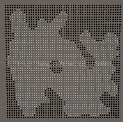
看不太清楚,放大看一下:
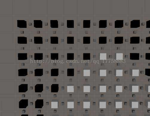
NICE!!正是我们想要的效果~!


 6593
6593


 被折叠的 条评论
为什么被折叠?
被折叠的 条评论
为什么被折叠?
 到【灌水乐园】发言


