


文章目录
Preface
Static timing analysis is a method of validating the timing performance of a design by checking all possible paths for timing violations. PrimeTime breaks a design down into timing paths, calculates the signal propagation delay along each path, and checks for violations of timing constraints inside the design and at the input/output interface.
一、Design Objects
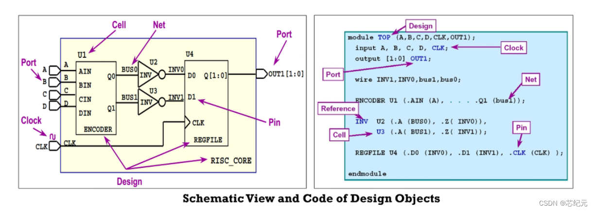
Synopsys commands, attributes, and constraints are directed toward the specific design objects described in this topic. Following figure shows the design objects.
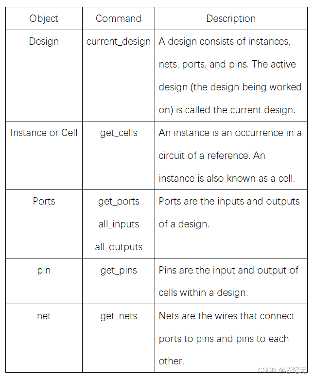
Following figure shows the detail design objects and commands.
二、Timing Paths
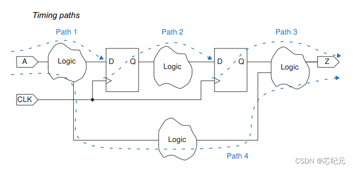
When performing timing analysis, PrimeTime first breaks down the design into timing paths. Each timing path consists of the following elements:
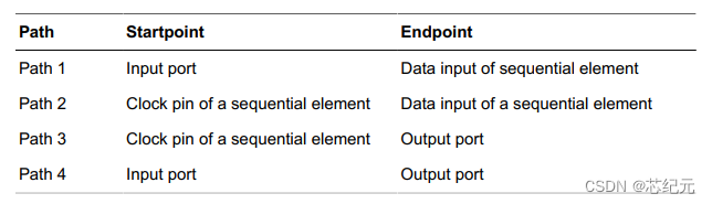
• Startpoint – The start of a timing path where data is launched by a clock edge or where the data must be available at a specific time. Every startpoint must be either an input port or a register clock pin.
• Combinational logic network – Elements that have no memory or internal state. Combinational logic can contain AND, OR, XOR, and inverter elements, but cannot contain flip-flops, latches, registers, or RAM.
• Endpoint – The end of a timing path where data is captured by a clock edge or where the data must be available at a specific time. Every endpoint must be either a register data input pin or an output port.
The following figure shows the timing paths in a simple design example.
三、Delay Calculation
After breaking down a design into a set of timing paths, the PrimeTime tool calculates the delay along each path. The total delay of a path is the sum of all cell and net delays in the path.
1. cell delay
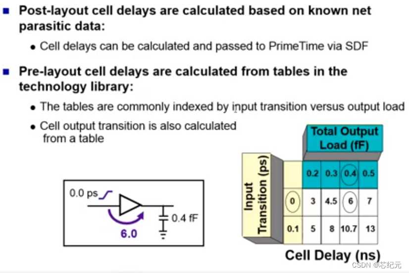
Cell delay is the amount of delay from input to output of a logic gate in a path. In the absence of back-annotated delay information from an SDF file, the tool calculates the cell delay from delay tables provided in the logic library for the cell.
Typically, a delay table lists the amount of delay as a function of one or more variables, such as input transition time and output load capacitance. From these table entries, the tool calculates each cell delay. When necessary, PrimeTime uses interpolation or extrapolation of table values to obtain a delay value for the current conditions specified for the design.
2. net delay
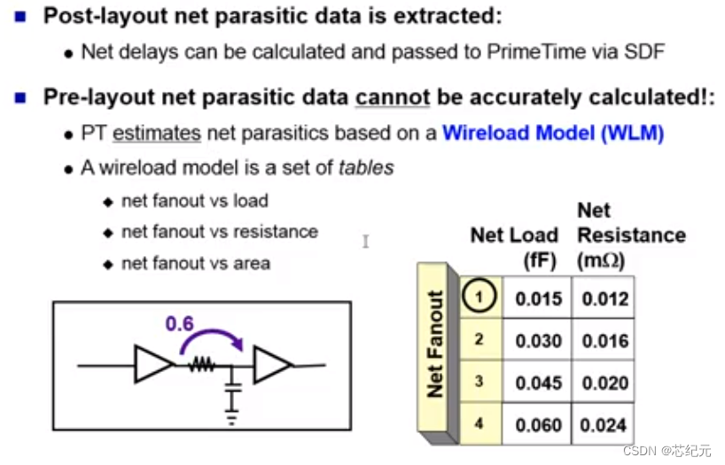
Net delay is the amount of delay from the output of a cell to the input of the next cell in a timing path. This delay is caused by the parasitic capacitance of the interconnection between the two cells, combined with net resistance and the limited drive strength of the cell driving the net.
The PrimeTime tool calculates net delays with the following methods:
• Estimating delays from a wire load model; this method is used before layout, when the chip topography is unknown
• Using specific time values back-annotated from a Standard Delay Format (SDF) file
• Using detailed parasitic resistance and capacitance data back-annotated from a Galaxy Parasitic Database (GPD), Standard Parasitic Exchange Format (SPEF), Detailed Standard Parasitic Format (DSPF), Reduced Standard Parasitic Format (RSPF) file
四、Constraint Checks
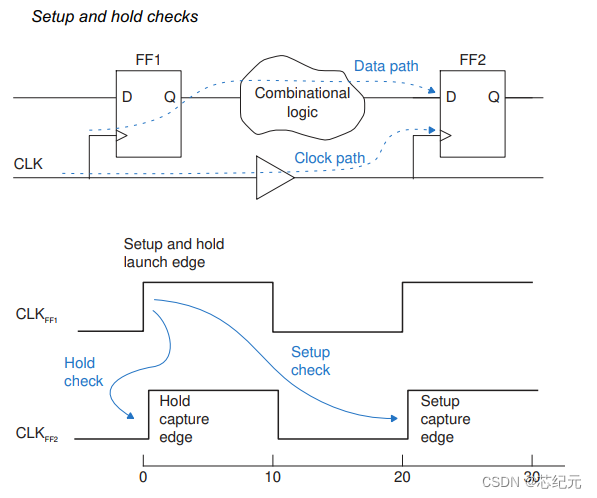
After PrimeTime determines the timing paths and calculates the path delays, it checks for violations of timing constraints, such as setup and hold constraints:
• A setup constraint specifies how much time is necessary for data to be available at the input of a sequential device before the clock edge that captures the data in the device. This constraint enforces a maximum delay on the data path relative to the clock edge.
• A hold constraint specifies how much time is necessary for data to be stable at the input of a sequential device after the clock edge that captures the data in the device. This constraint enforces a minimum delay on the data path relative to the clock edge.
In addition to setup and hold constraints, PrimeTime can also check recovery and removal constraints, data-to-data constraints, clock-gating setup and hold constraints, and the minimum pulse width for clock signals.
五、Timing Exceptions
By default, PrimeTime assumes that data launched at a path startpoint is captured at the path endpoint by the very next occurrence of a clock edge at the endpoint. For paths that are not intended to operate in this manner, you need to specify a timing exception. Otherwise, the timing analysis does not match the behavior of the real circuit. You can set the following timing exceptions:
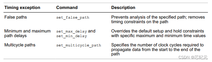
1. Setting false paths
A false path is a logic path that exists but should not be analyzed for timing. For example, a path can exist between two multiplexed logic blocks that are never selected at the same time, so that path is not valid for timing analysis.
For example, to declare a false path from pin FFB1/CP to pin FFB2/D:
pt_shell> set_false_path -from [get_pins FFB1/CP] -to [get_pins FFB2/D]
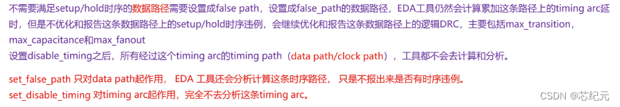
Declaring a path to be false removes all timing constraints from the path. PrimeTime still calculates the path delay, but does not report it to be an error, no matter how long or short the delay.
Setting a false path is a point-to-point timing exception. This is different from using the set_disable_timing command, which disables timing analysis for a specified pin, cell, or port. Using the set_disable_timing command removes the affected objects from timing analysis, rather than removing the timing constraints from the paths. If all paths through a pin are false, using set_disable_timing [get_pins pin_name] is more efficient than using set_false_path -through [get_pins pin_name] .
Another example of a false path is a path between flip-flops belonging to two clock domains that are asynchronous with respect to each other. To declare all paths between two clock domains to be false, you can use a set of two commands such as the following:
pt_shell> set_false_path -from [get_clocks ck1] -to [get_clocks ck2]
pt_shell> set_false_path -from [get_clocks ck2] -to [get_clocks ck1]
For efficiency, be sure to specify each clock by its clock name, not by the pin name (use get_clocks, not get_pins).
An alternative is to use the set_clock_groups command to exclude paths from consideration that are launched by one clock and captured by another. Although this has the same effect as declaring a false path between the two clocks, it is not considered a timing exception and is not reported by the report_exceptions command.
2. Setting Maximum and Minimum Path Delays
By default, PrimeTime calculates the maximum and minimum path delays by considering the clock edge times. To override the default maximum or minimum time with your own specific time value, use the set_max_delay or set_min_delay command. For example, to set the maximum path delay between registers REGA and REGB to 12, use this command:
pt_shell> set_max_delay 12.0 -from [get_cells REGA] -to [get_cells REGB]
With this timing exception, PrimeTime ignores the clock relationships. A path delay between these registers that exceeds 12 time units minus the setup requirement of the endpoint register is reported as a timing violation. Similarly, to set the minimum path delay between registers REGA and REGB to 2, use this command:
pt_shell> set_min_delay 2.0 -from [get_cells REGA] -to [get_cells REGB]
Again, PrimeTime ignores the clock relationships. A path delay between these registers that is less than 2 time units plus the hold requirement of the endpoint register is reported as a timing violation.
3. Setting Multicycle Paths
To specify the number of clock cycles required to propagate data from the start of a path to the end of the path, use the set_multicycle_path command. PrimeTime calculates the setup or hold constraint according to the specified number of cycles.
In the following example, the path from FF4 to FF5 is designed to take two clock cycles rather than one. However, by default, PrimeTime assumes single-cycle timing for all paths. Therefore, you need to specify a timing exception for this path.
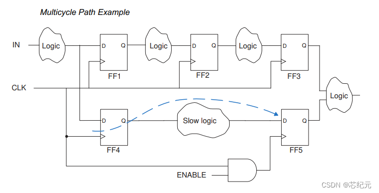
Although you could specify an explicit maximum delay value with the set_max_delay command, it is better to use the set_multicycle_path command, which automatically adjusts the maximum delay value if you change the clock period.
To set the multicycle path for the preceding example, use this command:
pt_shell> set_multicycle_path -setup 2 -from [get_cells FF4] -to [get_cells FF5]
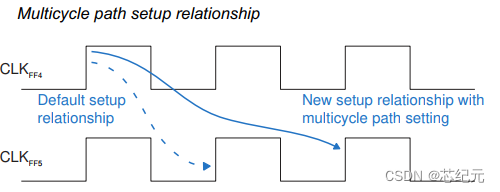
This command specifies that the path takes two clock cycles rather than one, establishing the new setup relationship shown below. The second capture edge (rather than the first) following the launch edge becomes the applicable edge for the end of the path.
Changing the setup relationship implicitly changes the hold relationship as well because all hold relationships are based on the valid setup relationships. PrimeTime verifies that the data launched by the setup launch edge is not captured by the previous capture edge. The new hold relationship is shown in the following figure.
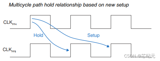
The new hold relationship is probably not the correct relationship for the design. If FF4 does not need to hold the data beyond the first clock edge, you need to specify another timing exception. Although you could use the set_min_delay command to specify an explicit hold time, it is better to use another set_multicycle_path command to move the capture edge for the hold relationship backward by one clock cycle. For example:
pt_shell> set_multicycle_path -setup 2 -from [get_cells FF4] -to [get_cells FF5]
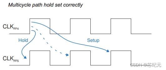
pt_shell> set_multicycle_path -hold 1 -from [get_cells FF4] -to [get_cells FF5]
Below shows the setup and hold relationships set correctly with two set_multicycle_path commands. The second set_multicycle_path command moves the capture edge of the hold relationship backward by one clock cycle, from the dashedline arrow to the solid-line arrow.
PrimeTime interprets the -setup and -hold options in the set_multicycle_path command differently:
• The integer value for the -setup option specifies the number of clock cycles for the multicycle path. In the absence of a timing exception, the default is 1.
• The integer value for the -hold option specifies the number of clock cycles to move the capture edge backward with respect to the default position (relative to the valid setup relationship); the default is 0.
Summary
Compared to dynamic simulation, static timing analysis is much faster because it is not necessary to simulate the logical operation of the circuit. Static timing analysis is also more thorough because it checks all timing paths, not just the logical conditions that are sensitized by a particular set of test vectors. However, static timing analysis can only check the timing, not the functionality, of a circuit design.


 1490
1490

 被折叠的 条评论
为什么被折叠?
被折叠的 条评论
为什么被折叠?
 到【灌水乐园】发言


