


最近在做UE4项目的时候,感觉自己对于贴图的部分理解还是不够,今天顺便复习一下。
本节内容,我们要学习如何导入贴图,并且把贴图映射到我们的物体上。
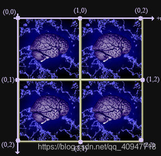
在DirectX3D中,我们使用UV坐标来映射贴图到物体。U是水平,V是垂直坐标。并且U,V都在0-1之间。所以当U,V都为1时,就是图像的结束位置。

如果我们把U,V的坐标都改成2的时候,它会在物体上重复
Global Declarations
声明的第一个接口对象是用来保存我们从文件中导入的贴图,
第二个接口对象是保存我们的采样信息的。
Vertex Structure/Input Layout
因为我们要对顶点进行UV映射,所以要在顶点结构中加入贴图坐标。
struct Vertex    //Overloaded Vertex Structure
{
    Vertex(){}
    Vertex(float x, float y, float z,
        float u, float v)
        : pos(x,y,z), texCoord(u, v){}

    XMFLOAT3 pos;
    XMFLOAT2 texCoord;
};

D3D11_INPUT_ELEMENT_DESC layout[] =
{
    { "POSITION", 0, DXGI_FORMAT_R32G32B32_FLOAT, 0, 0, D3D11_INPUT_PER_VERTEX_DATA, 0 },
    { "TEXCOORD", 0, DXGI_FORMAT_R32G32_FLOAT, 0, 12, D3D11_INPUT_PER_VERTEX_DATA, 0 },
};
Vertex Structure/Buffer, Indice List
我们需要对顶点结构也进行修改,因为我们之前定义了八个顶点,这其中可能会有一个顶点分享多个贴图坐标,为了避免这种情况出现,我们需要给每个面都单独设立顶点。
        Vertex v[] =
        {
            // Front Face
            Vertex(-1.0f, -1.0f, -1.0f, 0.0f, 1.0f),
            Vertex(-1.0f,  1.0f, -1.0f, 0.0f, 0.0f),
            Vertex( 1.0f,  1.0f, -1.0f, 1.0f, 0.0f),
            Vertex( 1.0f, -1.0f, -1.0f, 1.0f, 1.0f),

            // Back Face
            Vertex(-1.0f, -1.0f, 1.0f, 1.0f, 1.0f),
            Vertex( 1.0f, -1.0f, 1.0f, 0.0f, 1.0f),
            Vertex( 1.0f,  1.0f, 1.0f, 0.0f, 0.0f),
            Vertex(-1.0f,  1.0f, 1.0f, 1.0f, 0.0f),

            // Top Face
            Vertex(-1.0f, 1.0f, -1.0f, 0.0f, 1.0f),
            Vertex(-1.0f, 1.0f,  1.0f, 0.0f, 0.0f),
            Vertex( 1.0f, 1.0f,  1.0f, 1.0f, 0.0f),
            Vertex( 1.0f, 1.0f, -1.0f, 1.0f, 1.0f),

            // Bottom Face
            Vertex(-1.0f, -1.0f, -1.0f, 1.0f, 1.0f),
            Vertex( 1.0f, -1.0f, -1.0f, 0.0f, 1.0f),
            Vertex( 1.0f, -1.0f,  1.0f, 0.0f, 0.0f),
            Vertex(-1.0f, -1.0f,  1.0f, 1.0f, 0.0f),

            // Left Face
            Vertex(-1.0f, -1.0f,  1.0f, 0.0f, 1.0f),
            Vertex(-1.0f,  1.0f,  1.0f, 0.0f, 0.0f),
            Vertex(-1.0f,  1.0f, -1.0f, 1.0f, 0.0f),
            Vertex(-1.0f, -1.0f, -1.0f, 1.0f, 1.0f),

            // Right Face
            Vertex( 1.0f, -1.0f, -1.0f, 0.0f, 1.0f),
            Vertex( 1.0f,  1.0f, -1.0f, 0.0f, 0.0f),
            Vertex( 1.0f,  1.0f,  1.0f, 1.0f, 0.0f),
            Vertex( 1.0f, -1.0f,  1.0f, 1.0f, 1.0f),
        };

        DWORD indices[] = {
            // Front Face
            0,  1,  2,
            0,  2,  3,

            // Back Face
            4,  5,  6,
            4,  6,  7,

            // Top Face
            8,  9, 10,
            8, 10, 11,

            // Bottom Face
            12, 13, 14,
            12, 14, 15,

            // Left Face
            16, 17, 18,
            16, 18, 19,

            // Right Face
            20, 21, 22,
            20, 22, 23
        };

        D3D11_BUFFER_DESC indexBufferDesc;
        ZeroMemory( &indexBufferDesc, sizeof(indexBufferDesc) );

        indexBufferDesc.Usage = D3D11_USAGE_DEFAULT;
        indexBufferDesc.ByteWidth = sizeof(DWORD) * 12 * 3;
        indexBufferDesc.BindFlags = D3D11_BIND_INDEX_BUFFER;
        indexBufferDesc.CPUAccessFlags = 0;
        indexBufferDesc.MiscFlags = 0;

        D3D11_SUBRESOURCE_DATA iinitData;

        iinitData.pSysMem = indices;
        d3d11Device->CreateBuffer(&indexBufferDesc, &iinitData, &squareIndexBuffer);

        d3d11DevCon->IASetIndexBuffer( squareIndexBuffer, DXGI_FORMAT_R32_UINT, 0);


        D3D11_BUFFER_DESC vertexBufferDesc;
        ZeroMemory( &vertexBufferDesc, sizeof(vertexBufferDesc) );

        vertexBufferDesc.Usage = D3D11_USAGE_DEFAULT;
        vertexBufferDesc.ByteWidth = sizeof( Vertex ) * 24;
        vertexBufferDesc.BindFlags = D3D11_BIND_VERTEX_BUFFER;
        vertexBufferDesc.CPUAccessFlags = 0;
        vertexBufferDesc.MiscFlags = 0;
Loading the Texture from a File
函数原型如下
HRESULT D3DX11CreateShaderResourceViewFromFile(
  __in   ID3D11Device *pDevice,
  __in   LPCTSTR pSrcFile,
  __in   D3DX11_IMAGE_LOAD_INFO *pLoadInfo,
  __in   ID3DX11ThreadPump *pPump,
  __out  ID3D11ShaderResourceView **ppShaderResourceView,
  __out  HRESULT *pHResult
);
pDevice - 指向设备的指针
pSrcFile - 文件名字
pLoadInfo - 指向D3DX11_IMAGE_LOAD_INFO 结构体的指针,这个结构体定义了贴图是如何被导入的。我们这里设为NULL
pPump - 指向ID3DX11ThreadPump 的指针,只有使用多线程的时候才考虑,可以一边让图片加载,一边让程序运行
ppShaderResourceView - 保存图像数据对象的指针
pHResult - 函数返回结果
hr = D3DX11CreateShaderResourceViewFromFile( d3d11Device, L"braynzar.jpg",
    NULL, NULL, &CubesTexture, NULL );
Describing the Sample State
导入贴图之后,shader会如何渲染呢,我们需要定义一个采样状态。首先定义采样状态的描述信息。
typedef struct D3D11_SAMPLER_DESC {
  D3D11_FILTER               Filter;
  D3D11_TEXTURE_ADDRESS_MODE AddressU;
  D3D11_TEXTURE_ADDRESS_MODE AddressV;
  D3D11_TEXTURE_ADDRESS_MODE AddressW;
  FLOAT                      MipLODBias;
  UINT                       MaxAnisotropy;
  D3D11_COMPARISON_FUNC      ComparisonFunc;
  FLOAT                      BorderColor[4];
  FLOAT                      MinLOD;
  FLOAT                      MaxLOD;
} D3D11_SAMPLER_DESC;
Filter - 指定过滤方法
AddressU - 这是一个D3D11_TEXTURE_ADDRESS_MODE 枚举值,指定当U大于1或者小于0时的结果
AddressV - 同上
AddressW - 同上
MipLODBias - 从计算出的mipmap(这个概念不明白的可以google看看,很好理解)中的偏移。eg:当计算机算出贴图应该在mipmap的level3中采样,但是偏移为2,所以最终会在mipmap的Level 5中进行采样
MaxAnisotropy - 如果第一个参数指定了D3D11_FILTER_ANISOTROPIC or D3D11_FILTER_COMPARISON_ANISOTROPIC,那么会用一个夹紧值,有效数字为1-16
ComparisonFunc - 一个D3D11_COMPARISON_FUNC 枚举值,会比较mipmap数据和另一个mipmap采样数据
BorderColor[4] - 如果2 3 4中有一个指定了D3D11_TEXTURE_ADDRESS_BORDER ,那么这个颜色就会填充贴图和物体的边界区域。(只有u/v/w大于1时)
MaxLOD - 最大的mipmap等级,0是最大最清晰的,如果想要用所有的mipmap level,那么可以指定FLT_MAX
函数的参数默认值如下
Filter            MIN_MAG_MIP_LINEAR
AddressU        Clamp
AddressV        Clamp
AddressW        Clamp
MinLOD            -3.402823466e+38F (-FLT_MAX)
MaxLOD            3.402823466e+38F (FLT_MAX)
MipMapLODBias    0.0f
MaxAnisotropy    16
ComparisonFunc    Never
BorderColor        float4(0.0f,0.0f,0.0f,0.0f)
我们调用如下
D3D11_SAMPLER_DESC sampDesc;
ZeroMemory( &sampDesc, sizeof(sampDesc) );
sampDesc.Filter = D3D11_FILTER_MIN_MAG_MIP_LINEAR;
sampDesc.AddressU = D3D11_TEXTURE_ADDRESS_WRAP;
sampDesc.AddressV = D3D11_TEXTURE_ADDRESS_WRAP;
sampDesc.AddressW = D3D11_TEXTURE_ADDRESS_WRAP;
sampDesc.ComparisonFunc = D3D11_COMPARISON_NEVER;
sampDesc.MinLOD = 0;
sampDesc.MaxLOD = D3D11_FLOAT32_MAX;
创建好了采样状态的描述信息之后,我们就要设置采样状态了。
hr = d3d11Device->CreateSamplerState( &sampDesc, &CubesTexSamplerState );Sending the Sampler State and Texture to the Shader
我们可以对于一部分使用相同采样状态和相同贴图的物体集中调用函数,但是通常情况下,我们的一个物体都会有不同的贴图和采样状态,所以在实际使用中,我们需要对它调用多次
设置采样状态和贴图的函数分别为
ID3D11DeviceContext::PSSetSamplers().
ID3D11DeviceContext::PSSetShaderResources() 第一个参数是要发送的shader槽,第二个是要发送的贴图个数,第三个是保存了贴图数据的数组。
void DrawScene()
{
    //Clear our backbuffer
    float bgColor[4] = {(0.0f, 0.0f, 0.0f, 0.0f)};
    d3d11DevCon->ClearRenderTargetView(renderTargetView, bgColor);

    //Refresh the Depth/Stencil view
    d3d11DevCon->ClearDepthStencilView(depthStencilView, D3D11_CLEAR_DEPTH|D3D11_CLEAR_STENCIL, 1.0f, 0);

    //Set the WVP matrix and send it to the constant buffer in effect file
    WVP = cube1World * camView * camProjection;
    cbPerObj.WVP = XMMatrixTranspose(WVP);
    d3d11DevCon->UpdateSubresource( cbPerObjectBuffer, 0, NULL, &cbPerObj, 0, 0 );
    d3d11DevCon->VSSetConstantBuffers( 0, 1, &cbPerObjectBuffer );
    ///**************new**************
    d3d11DevCon->PSSetShaderResources( 0, 1, &CubesTexture );
    d3d11DevCon->PSSetSamplers( 0, 1, &CubesTexSamplerState );
    ///**************new**************

    //Draw the first cube
    d3d11DevCon->DrawIndexed( 36, 0, 0 );

    WVP = cube2World * camView * camProjection;
    cbPerObj.WVP = XMMatrixTranspose(WVP);
    d3d11DevCon->UpdateSubresource( cbPerObjectBuffer, 0, NULL, &cbPerObj, 0, 0 );
    d3d11DevCon->VSSetConstantBuffers( 0, 1, &cbPerObjectBuffer );
    ///**************new**************
    d3d11DevCon->PSSetShaderResources( 0, 1, &CubesTexture );
    d3d11DevCon->PSSetSamplers( 0, 1, &CubesTexSamplerState );
    ///**************new**************

    //Draw the second cube
    d3d11DevCon->DrawIndexed( 36, 0, 0 );

    //Present the backbuffer to the screen
    SwapChain->Present(0, 0);
}
通过以上的步骤,我们的贴图就设置好了,其实非常的简单,但是其中一些描述结构的参数的具体效果还需要我们一个一个摸索。
本节内容就到这里拉。
本节内容代码可以在我的Github找到
游戏开发路途遥远,但我相信只要坚持,总能到达彼岸!
如果我的文章对于你学习DirectX11有点帮助,欢迎评论给出建议,让我们一起学习进步!
———————— 小明 2018.12.3 18.09


 934
934

 被折叠的 条评论
为什么被折叠?
被折叠的 条评论
为什么被折叠?
 到【灌水乐园】发言


