


 本文详细介绍了VGA显示系统的原理,包括VGA接口、时序标准和显示模式。通过实验设计了一个25MHz时钟频率的VGA系统,分为四个模块:色彩栏、时钟生成、VGA控制器和图像生成。在EGO1实验板上实现了640x480@60Hz的显示模式,通过分频和模块化设计,成功输出RGB信号到显示器。
一、VGA
VGA,全称“Video Graphics Array”,及就是视频图形阵列,是一种使用模拟信号进行视频传输的标准协议,由IBM公司于1987年推出
二、VGA接口及引脚定义
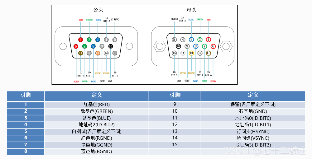
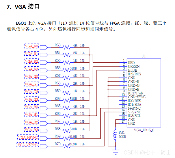
EGO1上VGA接口
VGA原理
VGA显示器采用 图像扫描 的方式进行图像显示,将构成图像的像素点,在行同步信号和场同步信号的同步下,按照从上到下、由左到右的顺序扫描到显示屏上。

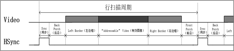
VGA时序标准
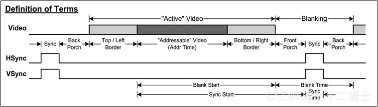
行扫描周期分为六个部分,分别是同步、后沿、左边框、有效图像、右边框和前沿。
场扫描也一样
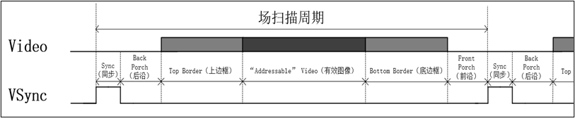
但是真正显示的部分是行、场扫描相交的部分
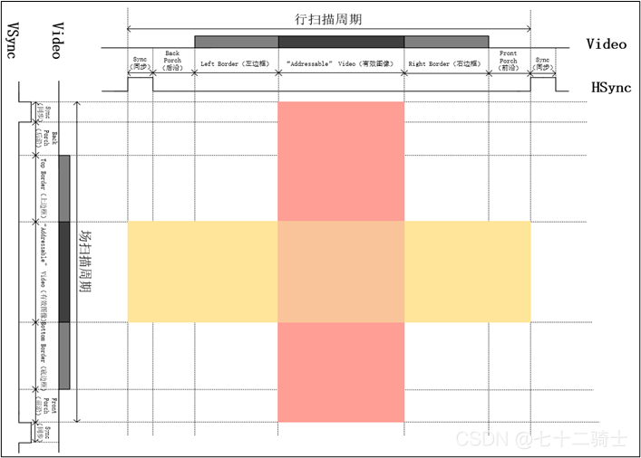
也就是中间红黄相间的地方
VGA显示模式及相关参数

时钟频率=行扫描周期x场扫描周期x帧(及就是@后的那个数字)
时钟频率的单位为MHz
设计
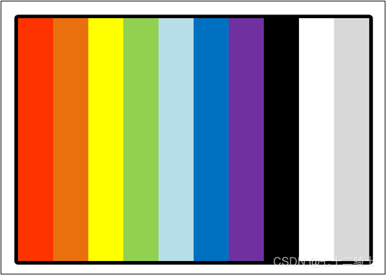
1.实验内容
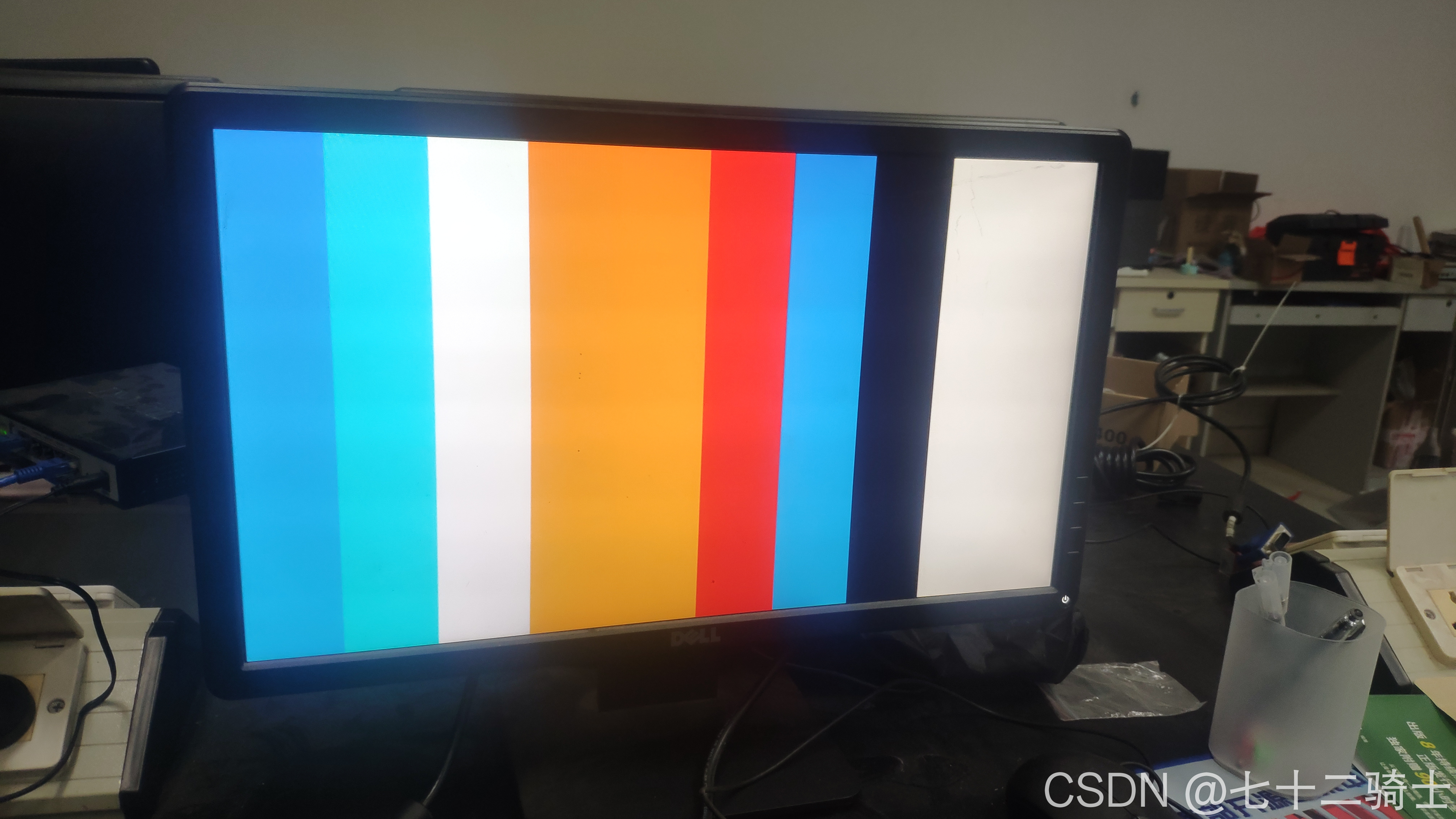
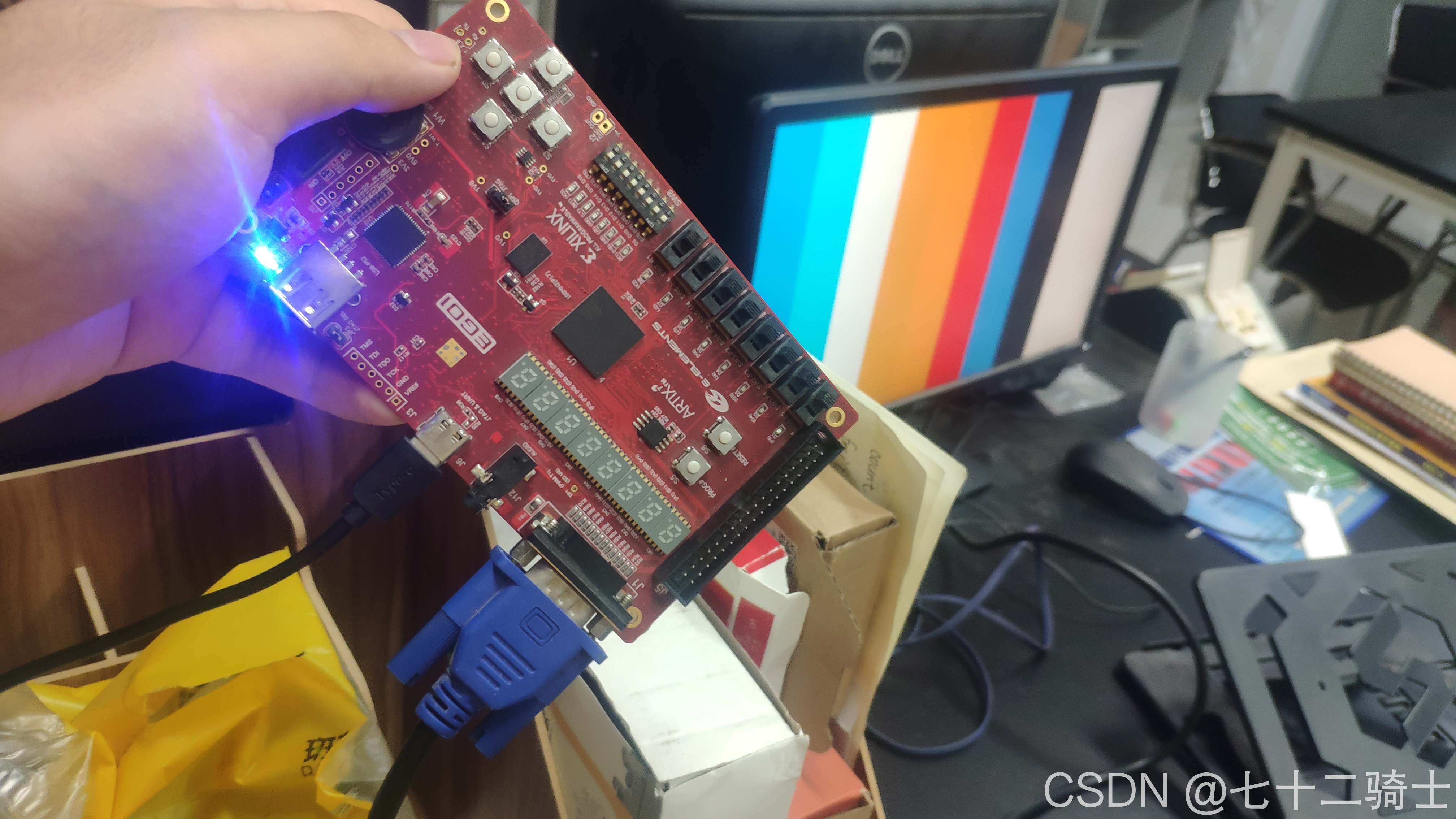
在EGO1的实验板上输出VGA数据到显示器上,效果应如下所示
2.分析
目标显示模式为640x480@60
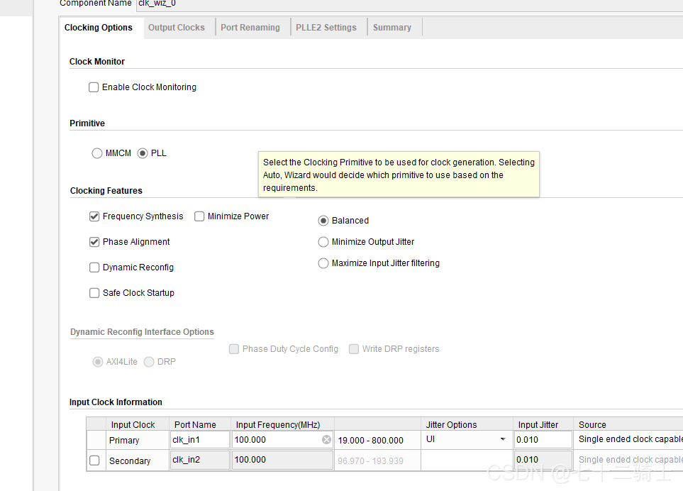
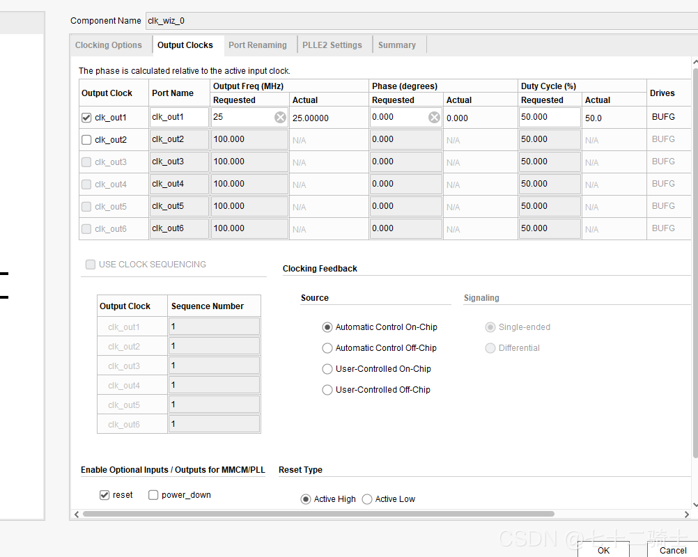
通过上面的表可以查到其时钟频率是25.175MHz,因为系统时钟是100MHz,想用100MHz来实现25.175MHz的分频无论是使用PLL锁相环还是使用RTL代码来实现都不是很方便,为了便于分频,选择25MHz,影响不大。
3.模块
根据实际需要,总共分为四个模块:
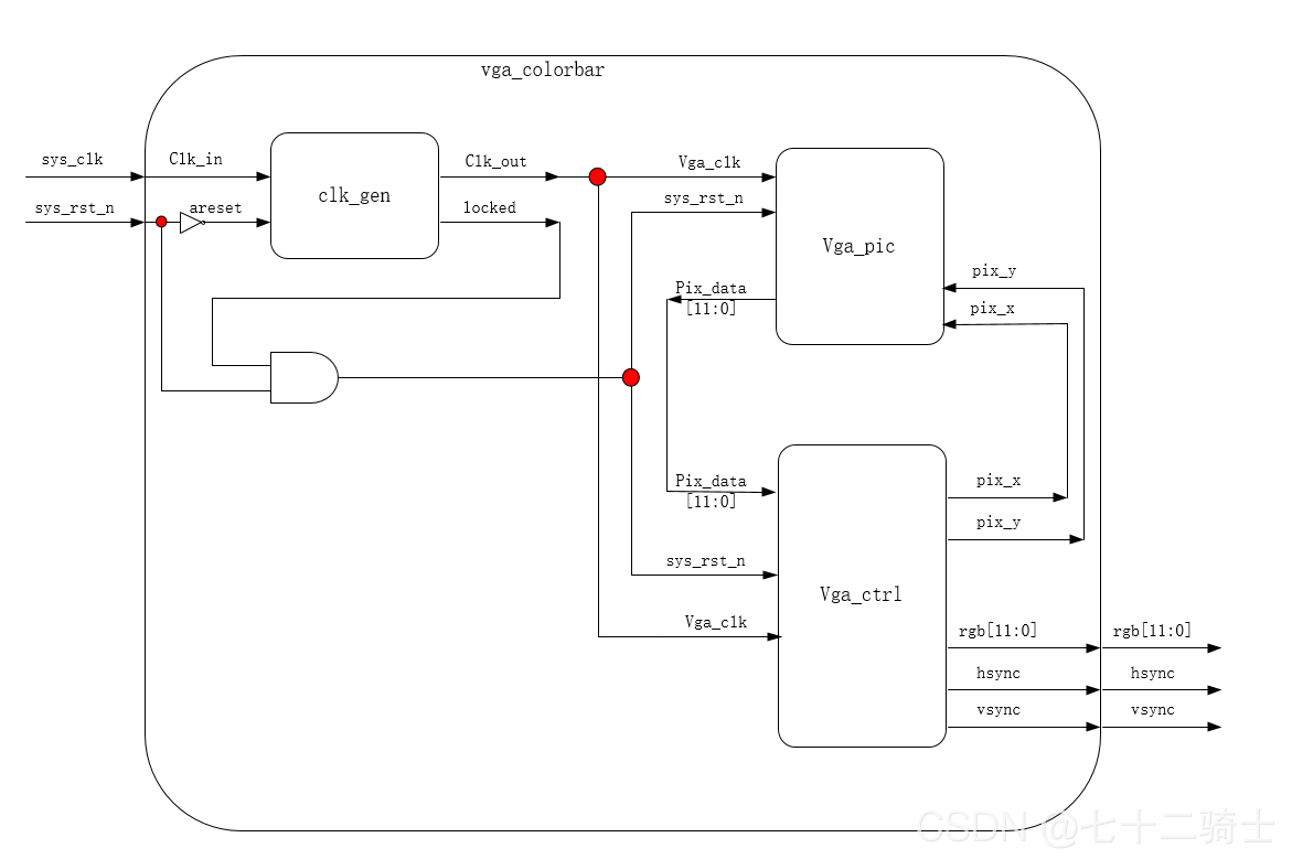
- vga_colobar:该模块为顶层模块,主要接受系统时钟和复位信号,输出12位rgb,因为EGO1的VGA接口是444类型的,所以总共是12位,该模块还输出hsync和vsync信号
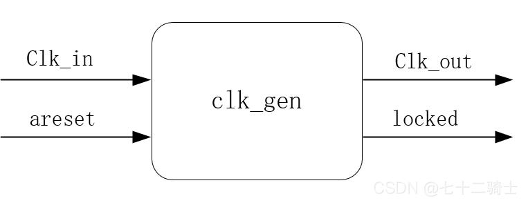
- clk_gen:该模块输入的是系统时钟,还有areset信号,输出clk_out和locked。该模块实现了分频,将系统时钟100MHz分频为25MHz,并通过clk_out输出
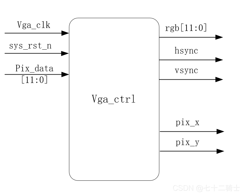
- vga_ctrl:该模块是vga驱动模块,在25MHz的工作时钟下,产生横纵坐标信号(pix_x,pix_y)---->(639,479),并且将该横纵坐标信号输出给vga_pic模块,生成行场、同步信号,再把pix_data像素点信息传输到rgb输出端口
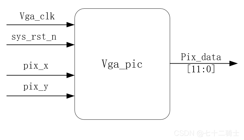
- vga_pic:根据输入的时钟信号、复位信号,以及坐标信号,产生pix_data像素信息
每个模块的框图如下:
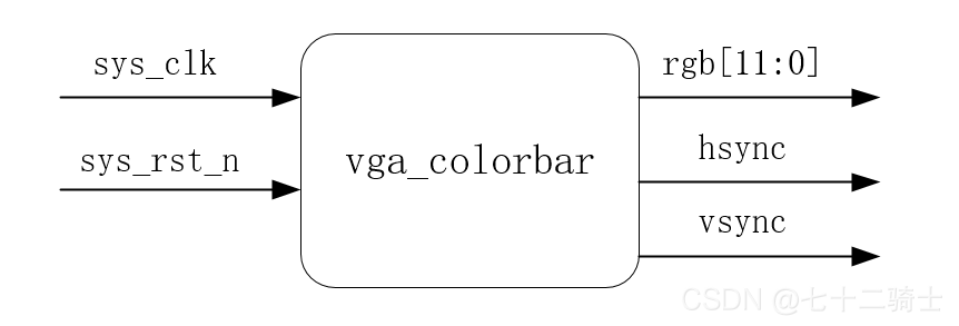
4.总体设计框图如下
编码测试
vga_ctrl.v:
`timescale 1ns / 1ps
//
// Company:
// Engineer:
//
// Create Date: 2021/08/25 21:49:05
// Design Name:
// Module Name: vga_ctrl
// Project Name:
// Target Devices:
// Tool Versions:
// Description:
//
// Dependencies:
//
// Revision:
// Revision 0.01 - File Created
// Additional Comments:
//
//


module vga_ctrl(
    input wire             vga_clk   ,
    input wire             sys_rst_n ,
    input wire    [11:0]   pix_data  ,

    output wire    [9:0]   pix_x    ,
    output wire    [9:0]   pix_y    ,
    output wire            hsync    ,
    output wire            vsync    ,
    output wire    [11:0]  vga_rgb
);


parameter H_SYNC   = 10'd96,
          H_BACK   = 10'd40,
          H_LEFT   = 10'd8,
          H_VALID  = 10'd640,
          H_RIGHT  = 10'd8,
          H_FRONT  = 10'd8,
          H_TOTAL  = 10'd800;

parameter V_SYNC   = 10'd2,
          V_BACK   = 10'd25,
          V_TOP    = 10'd8,
          V_VALID  = 10'd480,
          V_BOTTOM = 10'd8,
          V_FRONT  = 10'd2,
          V_TOTAL  = 10'd525;


reg [9:0]   cnt_h     ;
reg [9:0]   cnt_v     ;
wire        rgb_valid ;
wire        pix_data_req;

always @(posedge vga_clk or negedge sys_rst_n) begin
    if (sys_rst_n == 1'b0) begin
        cnt_h <= 10'd0;
    end
    else if (cnt_h == (H_TOTAL - 1'b1)) begin
        cnt_h <= 10'd0;
    end
    else begin
        cnt_h <= cnt_h + 10'd1;
    end
end

always @(posedge vga_clk or negedge sys_rst_n) begin
    if (sys_rst_n == 1'b0) begin
        cnt_v <= 10'd0;
    end
    else if ((cnt_h == (H_TOTAL - 1'b1)) && (cnt_v == (V_TOTAL - 1'b1))) begin
        cnt_v <= 10'd0;
    end
    else if (cnt_h == (H_TOTAL-1'b1)) begin
        cnt_v <= cnt_v + 10'd1;
    end
    else begin
        cnt_v <= cnt_v;
    end
end

assign rgb_valid = ((cnt_h >= H_SYNC + H_BACK + H_LEFT)
                    && (cnt_h < H_SYNC + H_BACK + H_LEFT + H_VALID)
                    && (cnt_v >= V_SYNC + V_BACK + V_TOP)
                    && (cnt_v < V_SYNC + V_BACK + V_TOP + V_VALID))
                    ?  1'b1 : 1'b0;

assign pix_data_req = ((cnt_h >= H_SYNC + H_BACK + H_LEFT - 1'b1)
                    && (cnt_h < H_SYNC + H_BACK + H_LEFT + H_VALID - 1'b1)
                    && (cnt_v >= V_SYNC + V_BACK + V_TOP)
                    && (cnt_v < V_SYNC + V_BACK + V_TOP + V_VALID))
                    ?  1'b1 : 1'b0;


assign pix_x = (pix_data_req == 1'b1) ? (cnt_h - (H_SYNC + H_BACK + H_LEFT) - 1'b1) : 10'd0;
assign pix_y = (pix_data_req == 1'b1) ? (cnt_v - (V_SYNC + V_BACK + V_TOP)) : 10'd0;
assign hsync = (cnt_h <= H_SYNC - 1'b1) ? 1'b1 : 1'b0;
assign vsync = (cnt_v <= V_SYNC - 1'b1) ? 1'b1 : 1'b0;
assign vga_rgb = (rgb_valid == 1'b1) ? pix_data : 12'h000;

endmodule
vga_pic.v:
`timescale 1ns / 1ps
//
// Company:
// Engineer:
//
// Create Date: 2021/08/26 19:53:47
// Design Name:
// Module Name: vga_pic
// Project Name:
// Target Devices:
// Tool Versions:
// Description:
//
// Dependencies:
//
// Revision:
// Revision 0.01 - File Created
// Additional Comments:
//
//


module vga_pic(
    input wire         vga_clk     ,
    input wire         sys_rst_n   ,
    input wire  [9:0]  pix_x       ,
    input wire  [9:0]  pix_y       ,

    output reg   [11:0]    pix_data
);

parameter H_VALID = 10'd640,
          V_VALID = 10'D480;

parameter   RED     = 12'hF80,
            ORANGE  = 12'hFC0,
            YELLOW  = 12'hFFE,
            GREEN   = 12'h07E,
            CYAN    = 12'h07F,
            BLUE    = 12'h01F,
            PURPPLE = 12'hF81,
            BLACK   = 12'h000,
            WHITE   = 12'hFFF,
            GRAY    = 12'hD69;

always@ (posedge vga_clk or negedge sys_rst_n) begin
    if (sys_rst_n == 1'b0) begin
        pix_data <= BLACK;
    end
    else if (pix_x >= 0 && pix_x < (H_VALID / 10) * 1) begin
        pix_data <= RED;
    end
    else if (pix_x >= ((H_VALID / 10) * 1) && pix_x < ((H_VALID / 10) * 2) ) begin
        pix_data <= ORANGE;
    end
    else if (pix_x >= ((H_VALID / 10) * 2) && pix_x < ((H_VALID / 10) * 3) ) begin
        pix_data <= YELLOW;
    end
    else if (pix_x >= ((H_VALID / 10) * 3) && pix_x < ((H_VALID / 10) * 4) ) begin
        pix_data <= GREEN;
    end
    else if (pix_x >= ((H_VALID / 10) * 4) && pix_x < ((H_VALID / 10) * 5) ) begin
        pix_data <= CYAN;
    end
    else if (pix_x >= ((H_VALID / 10) * 5) && pix_x < ((H_VALID / 10) * 6) ) begin
        pix_data <= BLUE;
    end
    else if (pix_x >= ((H_VALID / 10) * 6) && pix_x < ((H_VALID / 10) * 7) ) begin
        pix_data <= PURPPLE;
    end
    else if (pix_x >= ((H_VALID / 10) * 7) && pix_x < ((H_VALID / 10) * 8) ) begin
        pix_data <= BLACK;
    end
    else if (pix_x >= ((H_VALID / 10) * 8) && pix_x < ((H_VALID / 10) * 9) ) begin
        pix_data <= WHITE;
    end
    else if (pix_x >= ((H_VALID / 10) * 9) && pix_x < (H_VALID)) begin
        pix_data <= WHITE;
    end
    else begin
        pix_data <= BLACK;
    end
end
endmodule
vga_colorbar.v:
`timescale 1ns / 1ps
//
// Company:
// Engineer:
//
// Create Date: 2021/08/26 20:23:04
// Design Name:
// Module Name: vga_colorbar
// Project Name:
// Target Devices:
// Tool Versions:
// Description:
//
// Dependencies:
//
// Revision:
// Revision 0.01 - File Created
// Additional Comments:
//
//


module vga_colorbar(
    input wire        sys_clk,
    input wire        sys_rst_n,

    output wire       hsync,
    output wire       vsync,
    output wire  [11:0] vga_rgb
);


wire        vga_clk;
wire        locked;
wire        rst_n;

wire    [9:0]    pix_x;
wire    [9:0]    pix_y;
wire    [11:0]   pix_data;


assign  rst_n = (sys_rst_n && locked);


clk_wiz_0 clk_wiz_inst
(
  // Clock out ports
  .clk_out1(vga_clk),
  // Status and control signals
  .reset(~sys_rst_n),
  .locked(locked),
 // Clock in ports
  .clk_in1(sys_clk)
);

vga_ctrl vga_ctrl_inst
(
    .vga_clk  (vga_clk) ,
    .sys_rst_n(rst_n) ,
    .pix_data (pix_data) ,

    .pix_x    (pix_x  ),
    .pix_y    (pix_y  ),
    .hsync    (hsync  ),
    .vsync    (vsync  ),
    .vga_rgb  (vga_rgb)
);

vga_pic vga_pic_inst
(
    .vga_clk(vga_clk),
    .sys_rst_n(rst_n),
    .pix_x(pix_x),
    .pix_y(pix_y),

    .pix_data(pix_data)
);
endmodule
PLL:
结果


 2511
2511

 被折叠的 条评论
为什么被折叠?
被折叠的 条评论
为什么被折叠?
 到【灌水乐园】发言


