


HDLBits刷题记录
HDLBits是一个在线编程网站,可以直接在网站上编辑verilog代码,并进行综合仿真,查看波形图等,非常适合入门学习。
—— HDLBits的官网
注:可以配合B站的入门视频进行学习
—— Verilog硬件描述语言 西安电子科技大学 蔡觉平等主讲
1. Getting Started
编译后输出结果总共有四种,分别是:
Compile Error — Circuit did not compile.
Simulation Error — Circuit compiled successfully, but simulation did not complete.
Incorrect — Circuit compiled and simulated, but the outputs did not match the reference.
Success! — Circuit was correct
Getting Started
- Problem Statement
Build a circuit with no inputs and one output. That output should always drive 1 (or logic high).
- Code Block
答案仅供参考
module top_module( output one );

// Insert your code here
    assign one = 1;

endmodule
Output Zero
- Promblem Statement
Build a circuit with no inputs and one output that outputs a constant
0
- Code Block
答案仅供参考
module top_module(
    output zero
);// Module body starts after semicolon
	assign zero = 0;
endmodule
2. Verilog Language
Basics
Simple wire
Wire为连线型数据类型,是标准连线,代表着数据流向只有一个方向,从源端流向一个或者多个接收端。并且Wire为连续赋值语句,源端的任何变化都在在接收端立即体现出来。
-
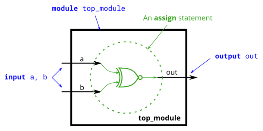
Problem Statement
Create a module with one input and one output that behaves like a wire.

问题示意图(转自HDLBits) -
Code Block
答案仅供参考
module top_module( in, out ); input wire in; output wire out; assign out = in; endmodule -
Key Point
-
连续型数据类型的声明
<net_declaration><drive_strength><range><delay>[list_of_variables];
net_declaration: 包括 wire、tri、tri0、tri1、wand 等
range: 用来指定数据为标量或为矢量,不写则代表数据为1位标量
delay: 仿真延迟时间
list_of_variables: 变量名称,可一次性定义多个名称
drive_strength: 表示连线变量的驱动强度
-
wire 在定义output和input时可以忽略不写,故也可这么写:
module top_module( input in, output out );
	assign out = in;
endmodule
-
Four wire
-
Problem Statement
Create a module with 3 inputs and 4 outputs that behaves like wires that makes these connections:
a -> w
b -> x
b -> y
c -> z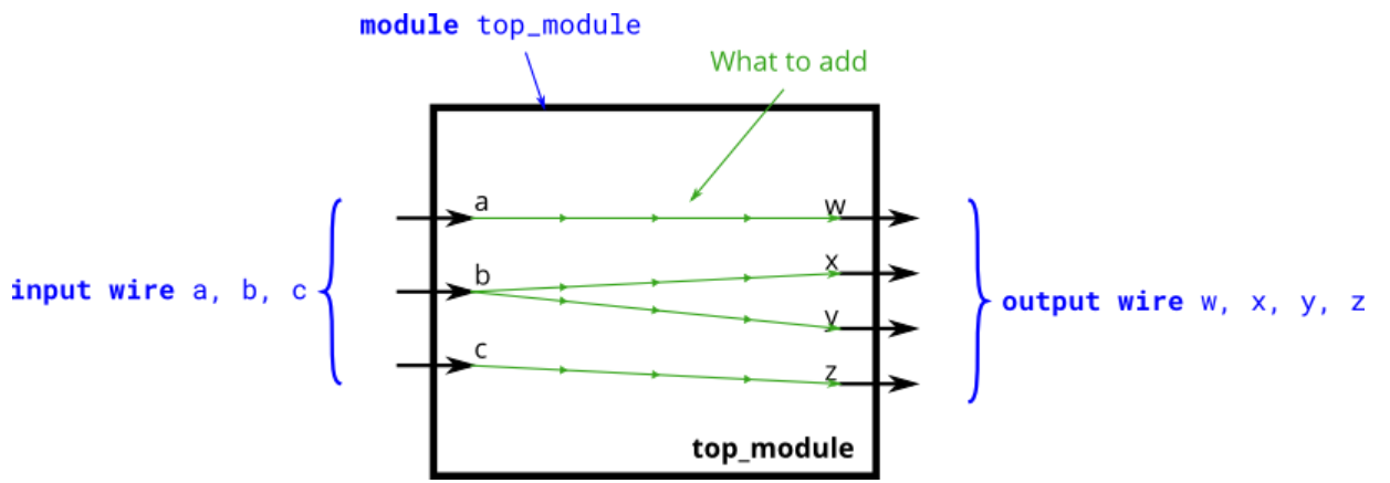
问题示意图(转自HDLBits) -
Code Block
module top_module(
    input a,b,c,
    output w,x,y,z );

    assign w = a;
    assign x = b;
    assign y = b;
    assign z = c;

endmodule
Inverter
-
Problem Statement
Create a module that implements a NOT gate.
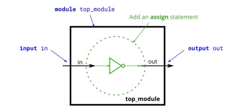
问题示意图(转自HDLBits) -
Code Block
module top_module( input in, output out );
	assign out = !in;
endmodule
-
Key Point
!是逻辑非运算,并不是按位取反^,故输出为0、1、x、z其中一种。
例如: a = 4’b1010,b = 4b’0000,则!a =0,!b = 1。
AND gate
-
Problem Statement
Create a module that implements an AND gate.
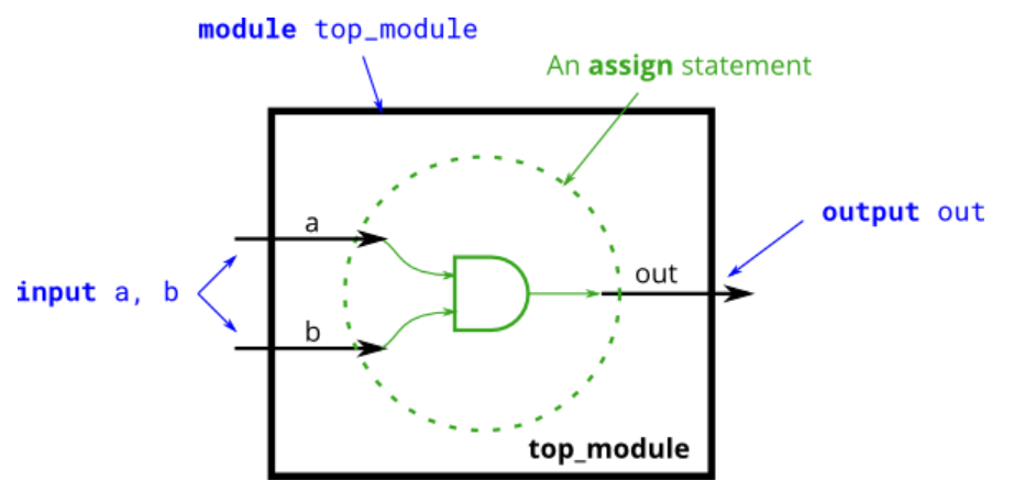
问题示意图(转自HDLBits) -
Code Block
module top_module(
    input a,
    input b,
    output out );
    assign out = a && b ;

endmodule
-
Key Point
逻辑与& 和 逻辑非!运算相同,输出只能为0、1、X、Z。
NOR gate
-
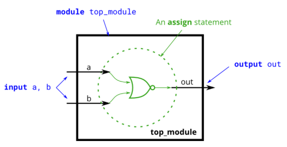
Problem statement
Create a module that implements a NOR gate. A NOR gate is an OR gate with its output inverted. A NOR function needs two operators when written in Verilog.
-
Code Block
module top_module(
    input a,
    input b,
    output out );

    assign out = !(a||b);
endmodule
XNOR gate
-
Problem Statement
Create a module that implements an XNOR gate.
-
Code Block
module top_module( input a, input b, output out ); assign out = ~(a^b) ; endmodule -
Key Point
同或门是XNOR gate,异或门是XOR gate。
异或门和同或门只有按位表达式没有逻辑表达式,其中按位异或是^,按位同或是 ^~
异或门的逻辑表达式为 F = A ⋅ B ′ + A ′ ⋅ B F = A·B' + A'·B F=A⋅B′+A′⋅B
同或门是异或门的非,逻辑表达式为 F = A ⋅ B + A ′ ⋅ B ′ F = A·B + A'·B' F=A⋅B+A′⋅B′
- 按照逻辑表达式,代码也能这么写:
module top_module(
    input a,
    input b,
    output out );
    assign out = (a && b) || ((!a) && (!b));
endmodule
Declaring wires
-
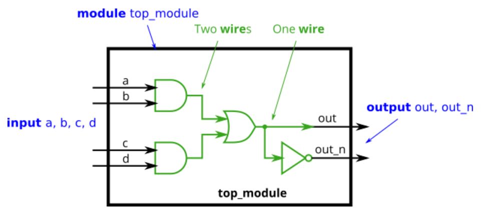
Problem Statement
Implement the following circuit. Create two intermediate wires (named anything you want) to connect the AND and OR gates together.
-
Code Block
module top_module(
    input a,
    input b,
    input c,
    input d,
    output out,
    output out_n   );

    wire and_1, and_2;
    assign and_1 = a && b;
    assign and_2 = c && d;
    assign out  = and_1 || and_2;
    assign out_n = !out ;

endmodule
7458 chip
-
Problem Statement
Create a module with the same functionality as the 7458 chip.

问题示意图(转自HDLBits) -
Code Block
module top_module (
    input p1a, p1b, p1c, p1d, p1e, p1f,
    output p1y,
    input p2a, p2b, p2c, p2d,
    output p2y );

    assign p2y = (p2a && p2b) || (p2c && p2d);
    assign p1y = (p1a && p1c && p1b) || (p1f && p1e && p1d);
endmodule
Vectors
Vectors
向量用于使用一个名称对相关信号进行分组,使其更便于操作。在Basics这一节中,使用wire时并没有定义它的位宽,所以都为1位的标量。
-
Problem Statement
Build a circuit that has one 3-bit input, then outputs the same vector, and also splits it into three separate 1-bit outputs.
-
Code Block
module top_module (
    input wire [2:0] vec,
    output wire [2:0] outv,
    output wire o2,
    output wire o1,
    output wire o0  ); // Module body starts after module declaration
    assign outv = vec;
    assign o2 = vec[2];
    assign o1 = vec[1];
    assign o0 = vec[0];

endmodule
Vector in more detail
-
Problem Statement
Build a combinational circuit that splits an input half-word (16 bits, [15:0] ) into lower [7:0] and upper [15:8] bytes.
-
Code Block
`default_nettype none // Disable implicit nets. Reduces some types of bugs. module top_module( input wire [15:0] in, output wire [7:0] out_hi, output wire [7:0] out_lo ); assign out_hi = in[15:8]; assign out_lo = in[7:0]; endmodule -
Key Point
-
Declaring Vectors
向量在声明时的顺序决定了它的高位和低位的数字,故我们在声明一个向量时,可以如下所示:
wire [2:0] w0; //高位为3,低位为0
assign w0 = 3'b110; // w0[2] =1 ,w0[1] =1 ,w0[0] = 0
wire [0:2] w1: //高位为0,低位为3
assign w1 = 3'b110;// w1[0] =1 ,w1[1] =1 ,w1[2] = 0
但在写代码的时候尽量保持顺序一致,如果一开始声明时为wire [2:0] w0,那么用w0[0:2]赋值就是错误的
-
Implicit nets
如果没有声明一个变量,那么在使用的时候默认是1位的,如果这时候使用assign语句将一个未声明的变量和一个向量连接在一起,那么只会获得向量的最低位,非常容易出现Bug。
我们可以通过宏定义 `default_nettype non来避免这种问题,如下所示:
wire [2:0] a, c; // 两个向量 assign a = 3'b101; // a = 101 assign b = a; // b = 1 隐式声明 wire assign c = b; // 出现Bug,因为b只有一位,而c有三位 my_module i1 (d,e); // 如果没有声明,d和e是只有一位位宽的隐式声明。 //我们通过声明宏定义`default_nettype non,让代码直接报错。 -
Unpacked vs. Packed Arrays
在声明向量时,可以将向量名前面声明向量位宽,如下所示:
reg [7:0] mem [255:0];   //256位的向量组,每组向量8位.
reg mem2 [28:0];         //没有声明的时候,每组向量组默认位1位
-
Vector part select
-
Problem Statement
A 32-bit vector can be viewed as containing 4 bytes (bits [31:24], [23:16], etc.). Build a circuit that will reverse the byte ordering of the 4-byte word.
AaaaaaaaBbbbbbbbCcccccccDddddddd => DdddddddCcccccccBbbbbbbbAaaaaaaa
-
Code Block
module top_module( input [31:0] in, output [31:0] out ); assign out[31:24] = in[7:0]; assign out[23:16] = in[15:8]; assign out[15:8] = in[23:16]; assign out[7:0] = in[31:24]; endmodule -
Key Point
module top_module(
    input [31:0] in,
    output [31:0] out );

    assign out[31:24] = in[0:7];
    assign out[23:16] = in[8:15];
    assign out[15:8] = in[16:23];
    assign out[7:0] = in[24:31];

endmodule
注:如果in写成in[0:7]而不是in[7:0]就会报错,因为一开始定义in的时候时[31:0]而不是[0:31],具体原因在上一节有讲。
Bitwise operators
-
Problem Statement
Build a circuit that has two 3-bit inputs that computes the bitwise-OR of the two vectors, the logical-OR of the two vectors, and the inverse (NOT) of both vectors. Place the inverse of
bin the upper half ofout_not(i.e., bits [5:3]), and the inverse ofain the lower half.

-
Code Block
module top_module(
    input [2:0] a,
    input [2:0] b,
    output [2:0] out_or_bitwise,
    output out_or_logical,
    output [5:0] out_not
);
    assign out_or_bitwise = a | b;
    assign out_or_logical = a || b;
    assign out_not[5:3] = ~b;
    assign out_not[2:0] = ~a;

endmodule
Four-input gates
-
Problem Statement
Build a combinational circuit with four inputs,
in[3:0].There are 3 outputs:
- out_and: output of a 4-input AND gate.
- out_or: output of a 4-input OR gate.
- out_xor: output of a 4-input XOR gate.
-
Code Block
module top_module( input [3:0] in, output out_and, output out_or, output out_xor ); assign out_and = ∈ assign out_or = |in; assign out_xor = ^in; endmodule -
Key Point
这里面进行都是按位运算,而不是逻辑运算,如果写完整的话可以这么写:
module top_module(
    input [3:0] in,
    output out_and,
    output out_or,
    output out_xor
);
    assign out_and = in[3] & in[2] & in[1] & in[0];
    assign out_or  = in[3] | in[2] | in[1] | in[0];
    assign out_xor = in[3] ^ in[2] ^ in[1] ^ in[0];

endmodule
Vector concatenation operator
-
Problem Statement
Given several input vectors, concatenate them together then split them up into several output vectors. There are six 5-bit input vectors: a, b, c, d, e, and f, for a total of 30 bits of input. There are four 8-bit output vectors: w, x, y, and z, for 32 bits of output. The output should be a concatenation of the input vectors followed by two
1bits: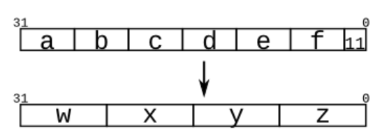
-
Code Block
module top_module ( input [4:0] a, b, c, d, e, f, output [7:0] w, x, y, z );// assign {w,x,y,z} = {a,b,c,d,e,f,2'b11}; endmodule -
Key Point
连接操作符用法非常简答,就是{向量,向量}
在合并向量的时候,注意要写上向量的位宽,不然会报错。
连接操作符可以在赋值的左右两边使用。
input [15:0] in;
output [23:0] out;
assign {out[7:0], out[15:8]} = in;
assign out[15:0] = {in[7:0], in[15:8]};    thing.
assign out = {in[7:0], in[15:8]};
Vector reversal
-
Problem Statement
Given an 8-bit input vector [7:0], reverse its bit ordering.
-
Code
module top_module(
    input [7:0] in,
    output [7:0] out
);
    assign out = {in[0], in[1], in[2], in[3], in[4], in[5], in[6], in[7]};
endmodule
Replication operator
-
Problem Statement
Build a circuit that sign-extends an 8-bit number to 32 bits. This requires a concatenation of 24 copies of the sign bit (i.e., replicate bit[7] 24 times) followed by the 8-bit number itself.
-
Code Block
module top_module ( input [7:0] in, output [31:0] out );// assign out = { {24{in[7]}}, in}; endmodule -
Key Point
复制操作符用法非常简单 {数字{向量}}
复制操作符可以组合使用,如下所示:
{5{1'b1}}           // 5'b11111
{2{a,b,c}}          // 和{a,b,c,a,b,c}一样
{3'd5, {2{3'd6}}}   // 9'b101_110_110,连接操作符可以和复制操作符一起组合使用
More replication
-
Problem Statement
Given five 1-bit signals (a, b, c, d, and e), compute all 25 pairwise one-bit comparisons in the 25-bit output vector. The output should be 1 if the two bits being compared are equal.
out[24] = ~a ^ a;   // a == a, so out[24] is always 1.
out[23] = ~a ^ b;
out[22] = ~a ^ c;
...
out[ 1] = ~e ^ d;
out[ 0] = ~e ^ e;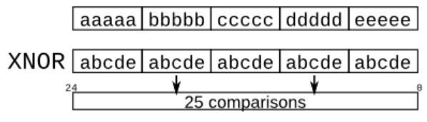
-
Code Block
module top_module (
    input a, b, c, d, e,
    output [24:0] out );

    assign out =~( {5{a,b,c,d,e}} ^ { {5{a}}, {5{b}}, {5{c}}, {5{d}}, {5{e}} } );

endmodule
Modules:Hierarchy
Modules
-
Problem Statemtent
create one instance of module
**mod_a**, then connect the module’s three pins (in1,in2, andout) to your top-level module’s three ports (wiresa,b, andout). The modulemod_ais provided for you — you must instantiate it.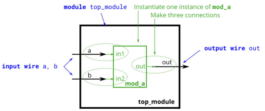
问题示意图(转自HDLBits) -
Code Block
module top_module ( input a, input b, output out ); mod_a instance1 (.in1(a), .in2(b), .out(out));//mod_a已经在HDLBits内定义好了,实例化它即可,不用自己写mod_a。 endmodule -
Key Point
模块化建模是将模块像积木一样搭建而成,我们在使用的时候不关心电路的内部结构,只在乎它的功能和接口,通过调用模块的方式使用它。
模块与模块之间不可以嵌套定义,只能在较顶层模块中实例化较底层的模块。
-
模块的调用方式
模块名<参数值列表> 实例名 (端口名列表);
-
模块多次调用
模块名 <参数值列表>实例名1(端口名列表1),
<参数值列表>实例名2(端口名列表2),
…
<参数值列表>实例名n(端口名列表n);
-
模块端口对应方式
(1)端口对应方式
调用模块按照顺序出现在端口连接列表中,要与模块名端口列表顺序一一对应,不可以打乱顺序。
模块名<参数值列表> 实例名 (<信号名1>, <信号名2>, … , <信号名n>)
(2)端口名对应方式(推荐)
通过直接写出端口名和信号名,实现一一对应效果,可以打乱顺序,方便查看对应信号,当有不需要的信号的时候,信号名可以为空。
模块名 <参数值列表> 实例名 (.端口名1<信号名1>, .端口名2<信号名2>,…, .端口名n<信号名n>)
module top_module ( input a, input b, output out );
    mod_a instance1 (.out(out), .in1(a), .in2(b));//端口名对应方式,可以打乱顺序。
    mod_a instance1 (a, b, out);//端口对应方式,不可以打乱顺序.
endmodule
-
Connecting ports by position
-
Problem Statement
You are given a module named
mod_athat has 2 outputs and 4 inputs, in that order. You must connect the 6 ports by position to your top-level module’s portsout1,out2,a,b,c, andd, in that order.You are given the following module:
module mod_a ( output, output, input, input, input, input );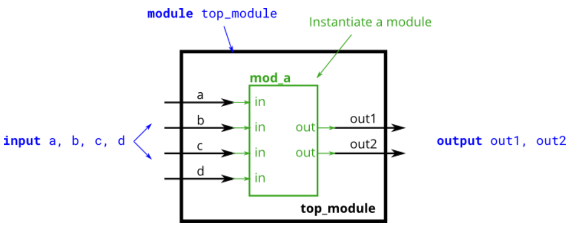
问题示意图(转自HDLBits) -
Code Block
module top_module (
   input a,
   input b,
   input c,
   input d,
   output out1,
   output out2
);
   mod_a instance1(out1, out2, a, b, c, d);//端口对应方式

endmodule
Connecting ports by name
-
Problem Statement
You are given a module named
mod_athat has 2 outputs and 4 inputs, in some order. You must connect the 6 ports by name to your top-level module’s ports:You are given the following module:
module mod_a ( output out1, output out2, input in1, input in2, input in3, input in4);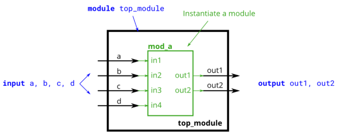
问题示意图(转自HDLBits) -
Code Block
module top_module (
    input a,
    input b,
    input c,
    input d,
    output out1,
    output out2
);
    mod_a instance1 (.out1(out1), .out2(out2), .in1(a), .in2(b), .in3(c), .in4(d));//端口名对应方式
endmodule
Three modules
-
Problem Statement
You are given a module
my_dffwith two inputs and one output (that implements a D flip-flop). Instantiate three of them, then chain them together to make a shift register of length 3. Theclkport needs to be connected to all instances.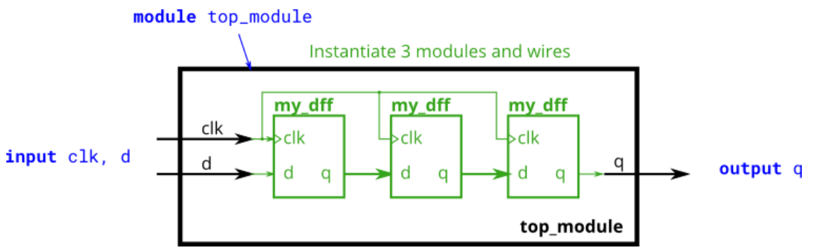
问题示意图(转自HDLBits) -
Code Block
module top_module ( input clk, input d, output q );

    wire q1, q2;

    my_dff instance1 (.clk(clk), .d(d),  .q(q1));
    my_dff instance2 (.clk(clk), .d(q1), .q(q2));
    my_dff instance3 (.clk(clk), .d(q2), .q(q) );

endmodule
Modules and vectors
-
Problem Statement
You are given a module
my_dff8with two inputs and one output (that implements a set of 8 D flip-flops). Instantiate three of them, then chain them together to make a 8-bit wide shift register of length 3. In addition, create a 4-to-1 multiplexer (not provided) that chooses what to output depending onsel[1:0]: The value at the input d, after the first, after the second, or after the third D flip-flop. (Essentially,selselects how many cycles to delay the input, from zero to three clock cycles.)The module provided to you is:
module my_dff8 ( input clk, input [7:0] d, output [7:0] q );The multiplexer is not provided. One possible way to write one is inside an
alwaysblock with acasestatement inside.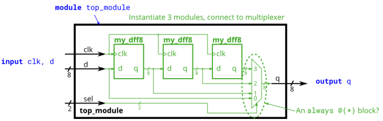
问题示意图(转自HDLBits) -
Code Block
module top_module (
    input clk,
    input [7:0] d,
    input [1:0] sel,
    output [7:0] q
);
    wire [7:0] q1,q2,q3;

    my_dff8 instance1 (.clk(clk), .d(d),  .q(q1));
    my_dff8 instance2 (.clk(clk), .d(q1), .q(q2));
    my_dff8 instance3 (.clk(clk), .d(q2), .q(q3));

    always@(*)				// *代表该模块的所有信号变化,都会触发always语句块。
        case(sel)			// case语句,输入值为sel,根据sel的值选择信号。
			2'b00: q = d;	// 输入sel=0时,输出q=d。
			2'b01: q = q1;	// 输入sel=1时,输出q=q1。
            2'b10: q = q2;	// 输入sel=2时,输出q=d2。
			2'b11: q = q3;	// 输入sel=3时,输出q=q3。
	endcase

endmodule
Adder 1
-
Problem Statement
You are given a module
add16that performs a 16-bit addition. Instantiate two of them to create a 32-bit adder. One add16 module computes the lower 16 bits of the addition result, while the second add16 module computes the upper 16 bits of the result, after receiving the carry-out from the first adder. Your 32-bit adder does not need to handle carry-in (assume 0) or carry-out (ignored), but the internal modules need to in order to function correctly. (In other words, theadd16module performs 16-bit a + b + cin, while your module performs 32-bit a + b).Connect the modules together as shown in the diagram below. The provided module
add16has the following declaration:module add16 ( input[15:0] **a**, input[15:0] **b**, input **cin**, output[15:0] **sum**, output **cout** );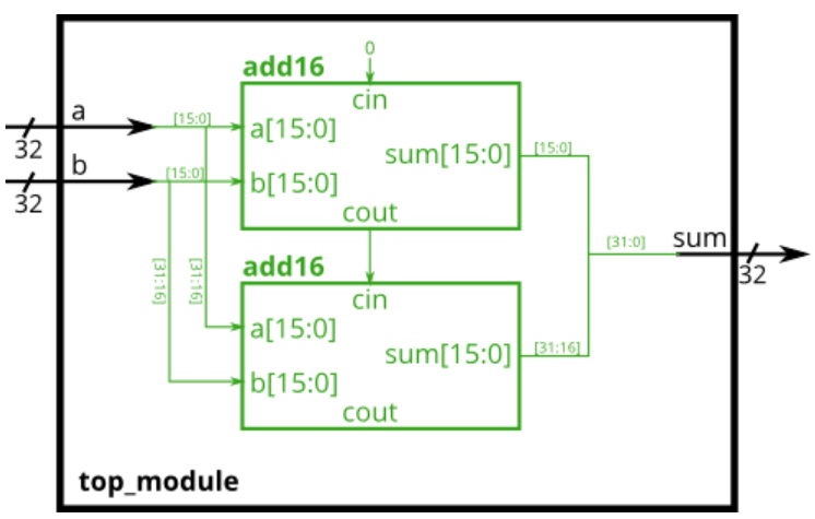
问题示意图(转自HDLBits) -
Code Block
module top_module(
    input [31:0] a,
    input [31:0] b,
    output [31:0] sum
);
    wire  cout_plus;
    add16 instance1(.a(a[15:0] ), .b(b[15:0] ), .cin(1'b0),      .cout(cout_plus), .sum(sum[15:0]) );
    add16 instance2(.a(a[31:16]), .b(b[31:16]), .cin(cout_plus), .cout(),          .sum(sum[31:16]));//coutm

endmodule
Adder2
-
Problem Statement
In this exercise, you will create a circuit with two levels of hierarchy. Your
top_modulewill instantiate two copies ofadd16(provided), each of which will instantiate 16 copies ofadd1(which you must write). Thus, you must write two modules:top_moduleandadd1.
-
Code Block
module top_module (
    input [31:0] a,
    input [31:0] b,
    output [31:0] sum
);//
    wire cout_plus;
    add16 instance1 (.a(a[15:0]),  .b(b[15:0]),  .cin(1'b0),      .cout(cout_plus), .sum(sum[15:0]) );
    add16 instance2 (.a(a[31:16]), .b(b[31:16]), .cin(cout_plus), .cout(),          .sum(sum[31:16]));

endmodule
//add1需要自己写,但是不需要自己创建实例
module add1 ( input a, input b, input cin,   output sum, output cout );
	assign sum = a^b^cin;
	assign cout = a&b | a&cin | b&cin;
endmodule
Carry-select adder
-
Problem Statement
In this exercise, you are provided with the same module
add16as the previous exercise, which adds two 16-bit numbers with carry-in and produces a carry-out and 16-bit sum. You must instantiate three of these to build the carry-select adder, using your own 16-bit 2-to-1 multiplexer.Connect the modules together as shown in the diagram below. The provided module
add16has the following declaration:module add16 ( input[15:0] **a**, input[15:0] **b**, input **cin**, output[15:0] **sum**, output **cout** );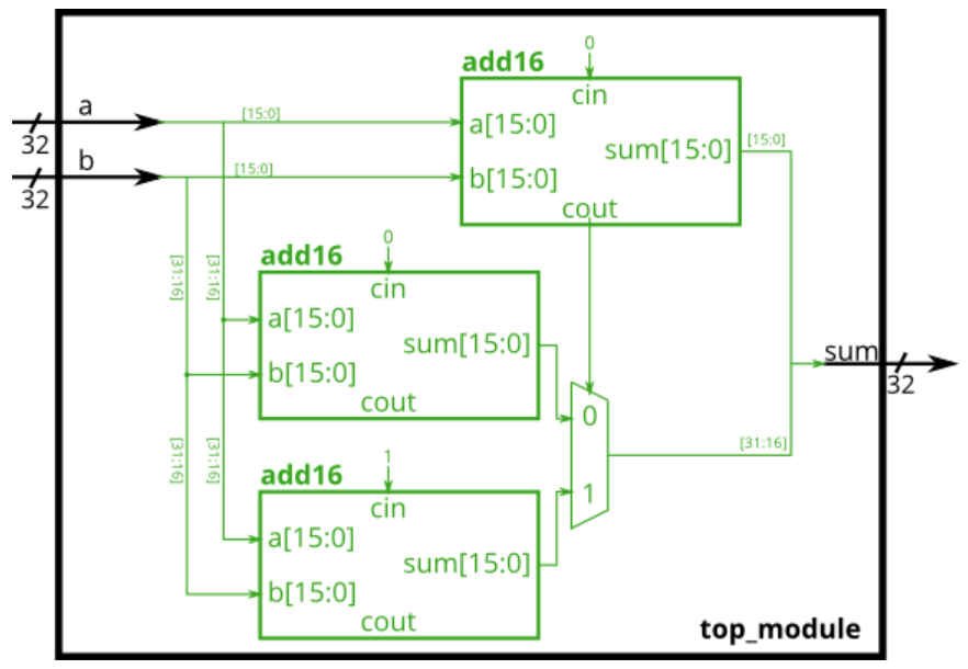
-
Code Block
module top_module( input [31:0] a, input [31:0] b, output [31:0] sum ); wire num; wire [15:0] out_0, out_1, out; add16 instance1 (.a(a[15:0]), .b(b[15:0]), .cin(1'b0), .cout(num), .sum(sum[15:0])); add16 instance2 (.a(a[31:16]), .b(b[31:16]), .cin(1'b0), .cout(), .sum(out_0) ); add16 instance3 (.a(a[31:16]), .b(b[31:16]), .cin(1'b1), .cout(), .sum(out_1) ); assign out = (num)?out_1:out_0;//这里是使用了条件运算符 assign sum[31:16] = out; endmodule -
Key Point
条件运算符的表达式为:
<条件表达式>?<表达式1>:<表达式0>;
其中条件表达式为1时,执行表达式1;条件表达式为0时,执行表达式0。
Adder-subtractor
-
Problem Statement
Build the adder-subtractor below.
You are provided with a 16-bit adder module, which you need to instantiate twice:
module add16 ( input[15:0] **a**, input[15:0] **b**, input **cin**, output[15:0] **sum**, output **cout** );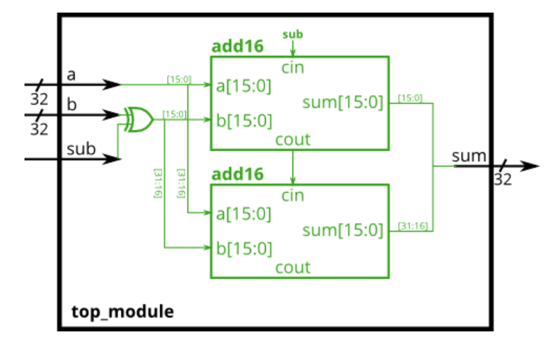
-
Code Block
module top_module(
    input [31:0] a,
    input [31:0] b,
    input sub,
    output [31:0] sum
);
    wire cout_0;
    wire [31:0] XOR_out;
    assign XOR_out = b ^ {32{sub}}; //复制运算符
    add16 instance1(.a(a[15:0] ), .b(XOR_out[15:0] ), .cin(sub),    .cout(cout_0), .sum(sum[15:0] ));
    add16 instance2(.a(a[31:16]), .b(XOR_out[31:16]), .cin(cout_0), .cout(),       .sum(sum[31:16]));
endmodule


 2670
2670


 被折叠的 条评论
为什么被折叠?
被折叠的 条评论
为什么被折叠?
 到【灌水乐园】发言


