


文章目录
- Finite State Machines
- Simple FSM 1_1(asynchronous reset)
- Simple FSM 1_2(synchronous reset)
- Simple FSM 2_1(asynchronous reset)
- Simple FSM 2_2(synchronous reset)
- Simple state transitions 3
- Simple one-hot state transitions 3
- Simple FSM 3_1(asynchronous reset)
- Simple FSM 3_2(synchronous reset)
- Design a Moore FSM
- Lemmings 1
- Lemmings 2
- Lemmings 3
- Lemmings 4
- One-hot FSM
- PS/2 packet parser
- PS/2 packet parser and datapath
- Serial receiver
- Serial receiver and datapath
- Serial receiver with parity checking
- Sequence recognition
- Q8:Design a Mealy FSM
- Q5a:Serial two's complementer(Moore FSM)
- Q5b: Serial two's complementer(Mealy FSM)
- Q3a:FSM
- Q3b:FSM
- Q3c:FSM logic
- Q6b: FSM next-state logic
- Q6b: FSM one-hot next-state logic
- Q6:FSM
- Q2a: FSM
- Q2b: One-hot FSM equations
- Q2a:FSM
- Q2b: Another FSM
- Buliding Larger Circuits
Finite State Machines
Simple FSM 1_1(asynchronous reset)
-
Problem Statement
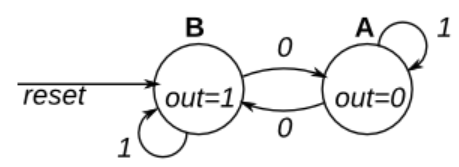
This is a Moore state machine with two states, one input, and one output. Implement this state machine. Notice that the reset state is B.

问题示意图(转自HDLBits) -
Code Block
module top_module(
    input clk,
    input areset,    // Asynchronous reset to state B
    input in,
    output out);//

    parameter A=0, B=1;
    reg state, next_state;

    always @(*) begin    // This is a combinational always block
        case(state)		//确定当前状态
            A : begin
                if(in == 1'b1)	begin	//根据输入选择下一状态
                    next_state <= A;
            	end
                else	begin
                    next_state <= B;
                end
            end
            B : begin
                if(in == 1'b1)	begin
                    next_state <= B;
            	end
                else	begin
                    next_state <= A;
                end
            end
        endcase
        // State transition logic
    end

    always @(posedge clk, posedge areset) begin    // This is a sequential always block
        // State flip-flops with asynchronous reset
        if(areset)	begin
            state <= B;
        end
        else	begin
            state <= next_state;	//这里不能是 next_state <= state
        end
    end

    // Output logic
    // assign out = (state == ...);
    assign out = (state == B);
endmodule
Simple FSM 1_2(synchronous reset)
-
Problem Statement
This is a Moore state machine with two states, one input, and one output. Implement this state machine. Notice that the reset state is B.
问题示意图(转自HDLBits) -
Code Block
// Note the Verilog-1995 module declaration syntax here:
module top_module(clk, reset, in, out);
    input clk;
    input reset;    // Synchronous reset to state B
    input in;
    output out;//
    reg out;

    // Fill in state name declarations
	parameter A=0, B=1;
    reg present_state, next_state;

    always@(*)		begin
        case (present_state)
            A : begin
                if (in == 1'b1)	begin
                    next_state <= A;
                end
                else	begin
                    next_state <= B;
                end
            end
            B : begin
                if (in == 1'b1)	begin
                    next_state <= B;
                end
                else	begin
                    next_state <= A;
                end
            end
        endcase
    end

	always @(posedge clk) begin
        if (reset) begin
            present_state <= B;
        end
        else	begin
            present_state = next_state;
        end
    end

    assign out = (present_state == B);
endmodule
Simple FSM 2_1(asynchronous reset)
-
Problem Statement
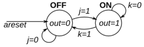
This is a Moore state machine with two states, two inputs, and one output. Implement this state machine.

-
Code Block
module top_module(
    input clk,
    input areset,    // Asynchronous reset to OFF
    input j,
    input k,
    output out); //

    parameter OFF=0, ON=1;
    reg state, next_state;

    always @(*) begin
        // State transition logic
        case(state)
             OFF : begin
                if(j == 0)	begin
                    next_state <= OFF;
                end
                else begin
                    next_state <= ON;
                end
            end
            ON : begin
                if(k == 0)	begin
                    next_state <= ON;
                end
                else begin
                    next_state <= OFF;
                end
            end
        endcase
    end

    always@(posedge clk, posedge areset) begin
        // State flip-flops with asynchronous reset
        if(areset)	begin
            state <= OFF;
        end
        else	begin
            state <= next_state;
        end
    end
    // Output logic
    assign out = (state == ON);

endmodule
Simple FSM 2_2(synchronous reset)
-
Problem Statement
This is a Moore state machine with two states, two inputs, and one output. Implement this state machine.
-
Code Block
module top_module(
    input clk,
    input reset,    // Asynchronous reset to OFF
    input j,
    input k,
    output out); //

    parameter OFF=0, ON=1;
    reg state, next_state;

    always @(*) begin
        // State transition logic
        case(state)
             OFF : begin
                if(j == 0)	begin
                    next_state <= OFF;
                end
                else begin
                    next_state <= ON;
                end
            end
            ON : begin
                if(k == 0)	begin
                    next_state <= ON;
                end
                else begin
                    next_state <= OFF;
                end
            end
        endcase
    end

    always@(posedge clk) begin
        // State flip-flops with asynchronous reset
        if(reset)	begin
            state <= OFF;
        end
        else	begin
            state <= next_state;
        end
    end
    // Output logic
    assign out = (state == ON);

endmodule
Simple state transitions 3
-
Problem Statement
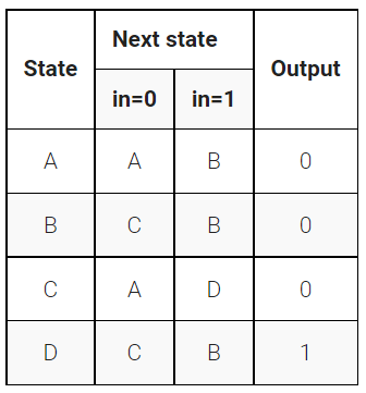
The following is the state transition table for a Moore state machine with one input, one output, and four states. Use the following state encoding: A=2’b00, B=2’b01, C=2’b10, D=2’b11.
Implement only the state transition logic and output logic (the combinational logic portion) for this state machine. Given the current state (
state), compute thenext_stateand output (out) based on the state transition table.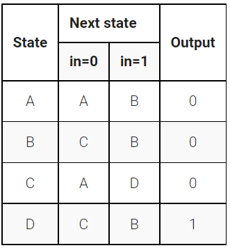
-
Code Block
module top_module(
    input in,
    input [1:0] state,
    output [1:0] next_state,
    output out); //

    parameter A=0, B=1, C=2, D=3;
    // State transition logic: next_state = f(state, in)
    // Output logic:  out = f(state) for a Moore state machine
    always@(*)	begin
        case(state)
            A : begin
                if(in == 1)	begin
                    next_state <= B;
                end
                else	begin
                    next_state <= A;
                end
            end
			B : begin
                if(in == 1)	begin
                    next_state <= B;
                end
                else	begin
                    next_state <= C;
                end
            end
            C : begin
                if(in == 1)	begin
                    next_state <= D;
                end
                else	begin
                    next_state <= A;
                end
            end
            D : begin
                if(in == 1)	begin
                    next_state <= B;
                end
                else	begin
                    next_state <= C;
                end
            end
        endcase
    end


    assign out = (state == D);

endmodule
Simple one-hot state transitions 3
-
Problem Statement
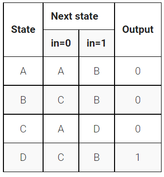
The following is the state transition table for a Moore state machine with one input, one output, and four states. Use the following one-hot state encoding: A=4’b0001, B=4’b0010, C=4’b0100, D=4’b1000.
Derive state transition and output logic equations by inspection assuming a one-hot encoding. Implement only the state transition logic and output logic (the combinational logic portion) for this state machine. (The testbench will test with non-one hot inputs to make sure you’re not trying to do something more complicated).
-
Code Block
module top_module(
    input in,
    input [3:0] state,
    output [3:0] next_state,
    output out); //

    parameter A=0, B=1, C=2, D=3;

    // State transition logic: Derive an equation for each state flip-flop.
    assign next_state[A] = (state[A] & (~in)) | (state[C] & (~in)); //由表可知,当前状态为A或者C并且输入为0时,下一状态才为A
    assign next_state[B] = (state[A] & in) | (state[B] & in) | (state[D] & in);
    assign next_state[C] = (state[B] & (~in)) | (state[D] & (~in));
    assign next_state[D] = (state[C] & in);

    // Output logic:
    assign out = state[D];

endmodule
Simple FSM 3_1(asynchronous reset)
-
Problem Statement
The following is the state transition table for a Moore state machine with one input, one output, and four states. Implement this state machine. Include an asynchronous reset that resets the FSM to state A.
-
Code Block
module top_module(
    input clk,
    input in,
    input areset,
    output out); //

	parameter A=0, B=1, C=2, D=3;
    reg [1:0] state,next_state;
    // State transition logic
    always@(*)	begin
        case(state)
            A : begin
                if(in)	begin
                    next_state <= B;
                end
                else	begin
                    next_state <= A;
                end
            end
            B : begin
                if(in)	begin
                    next_state <= B;
                end
                else	begin
                    next_state <= C;
                end
            end
            C : begin
                if(in)	begin
                    next_state <= D;
                end
                else	begin
                    next_state <= A;
                end
            end
            D : begin
                if(in)	begin
                    next_state <= B;
                end
                else	begin
                    next_state <= C;
                end
            end
        endcase
    end
    // State flip-flops with asynchronous reset
    always@(posedge clk or posedge areset)	begin
        if(areset)	begin
            state <= A;
        end
        else	begin
            state <= next_state;
        end
    end
    // Output logic
    assign out = (state == D);

endmodule
Simple FSM 3_2(synchronous reset)
-
Problem Statement
The following is the state transition table for a Moore state machine with one input, one output, and four states. Implement this state machine. Include a synchronous reset that resets the FSM to state A.

-
Code Block
module top_module(
    input clk,
    input in,
    input reset,
    output out); //

	parameter A=0, B=1, C=2, D=3;
    reg [1:0] state,next_state;
    // State transition logic
    always@(*)	begin
        case(state)
            A : begin
                if(in)	begin
                    next_state <= B;
                end
                else	begin
                    next_state <= A;
                end
            end
            B : begin
                if(in)	begin
                    next_state <= B;
                end
                else	begin
                    next_state <= C;
                end
            end
            C : begin
                if(in)	begin
                    next_state <= D;
                end
                else	begin
                    next_state <= A;
                end
            end
            D : begin
                if(in)	begin
                    next_state <= B;
                end
                else	begin
                    next_state <= C;
                end
            end
        endcase
    end
    // State flip-flops with asynchronous reset
    always@(posedge clk)	begin
        if(reset)	begin
            state <= A;
        end
        else	begin
            state <= next_state;
        end
    end
    // Output logic
    assign out = (state == D);

endmodule
Design a Moore FSM
-
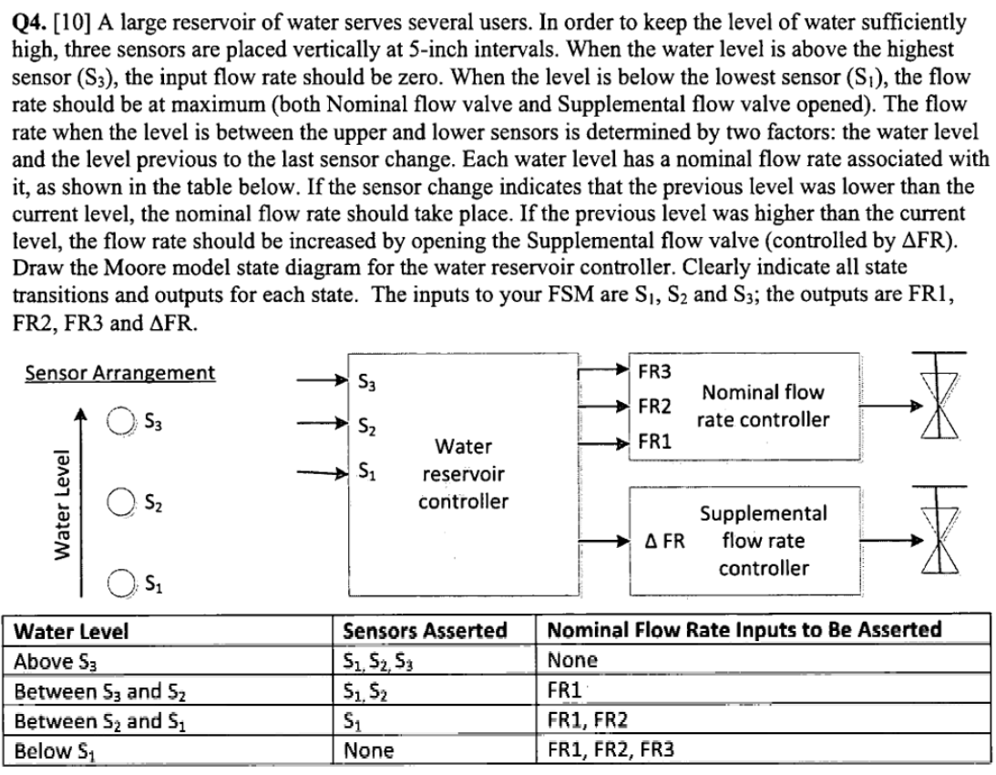
Problem Statement
-
Code Block
module top_module (
    input clk,
    input reset,
    input [3:1] s,
    output fr3,
    output fr2,
    output fr1,
    output dfr
);
    parameter S1B=0, S2A=1, S2B=2, S3A=3, S3B=4, S4A=5;	//S1,S2,S3代表水位;AB表示fr的关开
    reg [2:0] state,next_state;

    always@(*)	begin
        case(state)
            S1B : begin		//先从低水位开始排查
                if(s[1])	begin
                    next_state <= S2A;	//S1水位有水,继续往上查
                end
                else	begin
                    next_state <= S1B;	//水位最低
                end
            end

            S2A : begin
                if(s[2])	begin
                    next_state <= S3A;	//S2水位有水,继续往上查
                end
                else	begin
                    if(s[1])	begin
                        next_state <= S2A;
                    end
                    else	begin
                        next_state <= S1B;
                    end
                end
            end
            S2B : begin
                if(s[2])	begin
                    next_state <= S3A;	//S2水位有水,继续往上查
                end
                else	begin
                    if(s[1])	begin
                        next_state <= S2B;
                    end
                    else	begin
                        next_state <= S1B;
                    end
                end
            end
            S3A : begin
                if(s[3])	begin
                    next_state <= S4A;	//S3水位有水,继续往上查
                end
                else	begin
                    if(s[2])	begin
                        next_state <= S3A;
                    end
                    else	begin
                        next_state <= S2B;
                    end
                end
            end
            S3B : begin
                if(s[3])	begin
                    next_state <= S4A;	//S3水位有水,继续往上查
                end
                else	begin
                    if(s[2])	begin
                        next_state <= S3B;
                    end
                    else	begin
                        next_state <= S2B;
                    end
                end
            end
            S4A : begin
                if(s[3])	begin
                    next_state <= S4A;
                end
                else	begin
                    next_state <= S3B;
                end
            end
            default : next_state <= 'x;	//输出未知态,'x代表自适应位宽的X
        endcase
    end

    always@(posedge clk)	begin
        if(reset)	begin
            state <= S1B;
        end
        else	begin
            state <= next_state;
        end
    end

    always @(*)begin
        case(state)
            S1B:{fr3,fr2,fr1,dfr} = 4'b1111;
            S2A:{fr3,fr2,fr1,dfr} = 4'b0110;
            S2B:{fr3,fr2,fr1,dfr} = 4'b0111;
            S3A:{fr3,fr2,fr1,dfr} = 4'b0010;
            S3B:{fr3,fr2,fr1,dfr} = 4'b0011;
            S4A:{fr3,fr2,fr1,dfr} = 4'b0000;
            default:{fr3,fr2,fr1,dfr} = 'x;
        endcase
    end
endmodule
Lemmings 1
-
Problem Statement
The game Lemmings involves critters with fairly simple brains. So simple that we are going to model it using a finite state machine.
In the Lemmings’ 2D world, Lemmings can be in one of two states: walking left or walking right. It will switch directions if it hits an obstacle. In particular, if a Lemming is bumped on the left, it will walk right. If it’s bumped on the right, it will walk left. If it’s bumped on both sides at the same time, it will still switch directions.
Implement a Moore state machine with two states, two inputs, and one output that models this behaviour.
-
Code Block
module top_module(
    input clk,
    input areset,    // Freshly brainwashed Lemmings walk left.
    input bump_left,
    input bump_right,
    output walk_left,
    output walk_right); //

    parameter LEFT=0, RIGHT=1;
    reg state, next_state;

    always @(*) begin
        // State transition logic
        case(state)
            LEFT : begin
                if(~bump_left)	begin
                    next_state <= LEFT;
                end
                else	begin
                    next_state <= RIGHT;
                end
            end
            RIGHT : begin
                if(~bump_right)	begin
                    next_state <= RIGHT;
                end
                else	begin
                    next_state <= LEFT;
                end
            end
        endcase
    end

    always @(posedge clk, posedge areset) begin
        // State flip-flops with asynchronous reset
        if(areset)	begin
            state <= LEFT;
        end
        else	begin
            state <= next_state;
        end
    end

    // Output logic
    assign walk_left  = (state == LEFT);
    assign walk_right = (state == RIGHT);

endmodule
Lemmings 2
-
Problem Statement
In addition to walking left and right, Lemmings will fall (and presumably go “aaah!”) if the ground disappears underneath them.
In addition to walking left and right and changing direction when bumped, when
ground=0, the Lemming will fall and say “aaah!”. When the ground reappears (ground=1), the Lemming will resume walking in the same direction as before the fall. Being bumped while falling does not affect the walking direction, and being bumped in the same cycle as ground disappears (but not yet falling), or when the ground reappears while still falling, also does not affect the walking direction.Build a finite state machine that models this behaviour.
-
Code Block
module top_module(
    input clk,
    input areset,    // Freshly brainwashed Lemmings walk left.
    input bump_left,
    input bump_right,
    input ground,
    output walk_left,
    output walk_right,
    output aaah );

    parameter LEFT=0, RIGHT=1, FALLL=2, FALLR=3;
    reg [1:0] state, next_state;

    always @(*) begin
        // State transition logic
        case(state)
            LEFT : begin
                if(~bump_left & ground)		begin
                    next_state <= LEFT;
                end
                else if(~ground)	begin
                    next_state <= FALLL;
                end
                else	begin
                    next_state <= RIGHT;
                end
            end
            RIGHT : begin
                if(~bump_right & ground)	begin
                    next_state <= RIGHT;
                end
                else if(~ground)	begin
                    next_state <= FALLR;
                end
                else	begin
                    next_state <= LEFT;
                end
            end
            FALLL : begin
                if(ground)	begin
                    next_state <= LEFT;
                end
                else	begin
                    next_state <= FALLL;
                end
            end
            FALLR : begin
                if(ground)	begin
                    next_state <= RIGHT;
                end
                else	begin
                    next_state <= FALLR;
                end
            end
        endcase
    end

    always@(posedge clk or posedge areset)begin
        if(areset)begin
            state <= LEFT;
        end
        else begin
            state <= next_state;
        end
    end

    assign walk_left = (state == LEFT);
    assign walk_right = (state == RIGHT);
    assign aaah = ((state == FALLL) | (state == FALLR));
endmodule
Lemmings 3
-
Problem Statement
In addition to walking and falling, Lemmings can sometimes be told to do useful things, like dig (it starts digging when
dig=1). A Lemming can dig if it is currently walking on ground (ground=1and not falling), and will continue digging until it reaches the other side (ground=0). At that point, since there is no ground, it will fall (aaah!), then continue walking in its original direction once it hits ground again. As with falling, being bumped while digging has no effect, and being told to dig when falling or when there is no ground is ignored.(In other words, a walking Lemming can fall, dig, or switch directions. If more than one of these conditions are satisfied, fall has higher precedence than dig, which has higher precedence than switching directions.)
-
Code Block
module top_module(
    input clk,
    input areset,    // Freshly brainwashed Lemmings walk left.
    input bump_left,
    input bump_right,
    input ground,
    input dig,
    output walk_left,
    output walk_right,
    output aaah,
    output digging );

    parameter LEFT=0, RIGHT=1, FALLL=2, FALLR=3, DIGL=4, DIGR=5;
    reg [2:0] state, next_state;

    always @(*)	begin
        case(state)
            LEFT : begin
                if( (~dig) & (~bump_left) & ground)		begin
                    next_state <= LEFT;
                end
                else if(~ground)	begin
                    next_state <= FALLL;
                end
                else if(dig)	begin
                    next_state <= DIGL;
                end
                else	begin
                    next_state <= RIGHT;
                end
            end
            RIGHT : begin
                if((~dig) & ~bump_right & ground)	begin
                    next_state <= RIGHT;
                end
                else if(~ground)	begin
                    next_state <= FALLR;
                end
                else if(dig)	begin
                    next_state <= DIGR;
                end
                else	begin
                    next_state <= LEFT;
                end
            end
            FALLL : begin
                if(ground)	begin
                    next_state <= LEFT;
                end
                else	begin
                    next_state <= FALLL;
                end
            end
            FALLR : begin
                if(ground)	begin
                    next_state <= RIGHT;
                end
                else	begin
                    next_state <= FALLR;
                end
            end
            DIGL : begin
                if(~ground)	begin
                    next_state <= FALLL;
                end
                else	begin
                    next_state <= DIGL;
                end
            end
            DIGR : begin
                if(~ground)	begin
                    next_state <= FALLR;
                end
                else	begin
                    next_state <= DIGR;
                end
            end
        endcase
    end

    always@(posedge clk or posedge areset)begin
        if(areset)begin
            state <= LEFT;
        end
        else begin
            state <= next_state;
        end
    end

    assign walk_left = (state == LEFT);
    assign walk_right = (state == RIGHT);
    assign aaah = ((state == FALLL) | (state == FALLR));
    assign	digging = ((state == DIGL) | (state == DIGR));

endmodule
Lemmings 4
-
Problem Statement
Although Lemmings can walk, fall, and dig, Lemmings aren’t invulnerable. If a Lemming falls for too long then hits the ground, it can splatter. In particular, if a Lemming falls for more than 20 clock cycles then hits the ground, it will splatter and cease walking, falling, or digging (all 4 outputs become 0), forever (Or until the FSM gets reset). There is no upper limit on how far a Lemming can fall before hitting the ground. Lemmings only splatter when hitting the ground; they do not splatter in mid-air.
-
Code Block
module top_module(
    input clk,
    input areset,    // Freshly brainwashed Lemmings walk left.
    input bump_left,
    input bump_right,
    input ground,
    input dig,
    output walk_left,
    output walk_right,
    output aaah,
    output digging );

    parameter LEFT=0, RIGHT=1, FALLL=2, FALLR=3, DIGL=4, DIGR=5, SPLAT=6, DEAD=7;
    reg [2:0] state, next_state;
    reg [4:0] cycle;

    always @(*)	begin
        case(state)
            LEFT : begin
                if( (~dig) & (~bump_left) & ground )		begin
                    next_state <= LEFT;
                end
                else if(~ground)	begin
                    next_state <= FALLL;
                end
                else if(dig)	begin
                    next_state <= DIGL;
                end
                else	begin
                    next_state <= RIGHT;
                end
            end
            RIGHT : begin
                if((~dig) & ~bump_right & ground)	begin
                    next_state <= RIGHT;
                end
                else if(~ground)	begin
                    next_state <= FALLR;
                end
                else if(dig)	begin
                    next_state <= DIGR;
                end
                else	begin
                    next_state <= LEFT;
                end
            end
            FALLL : begin
                if(ground)	begin
                    next_state <= LEFT;
                end
                else if(cycle >= 20)	begin
                    next_state <= SPLAT;
                end
                else	begin
                    next_state <= FALLL;
                end
            end
            FALLR : begin
                if(ground)	begin
                    next_state <= RIGHT;
                end
                else if(cycle >= 20)	begin
                    next_state <= SPLAT;
                end
                else	begin
                    next_state <= FALLR;
                end
            end
            DIGL : begin
                if(~ground)	begin
                    next_state <= FALLL;
                end
                else	begin
                    next_state <= DIGL;
                end
            end
            DIGR : begin
                if(~ground)	begin
                    next_state <= FALLR;
                end
                else	begin
                    next_state <= DIGR;
                end
            end

            SPLAT : begin
                if(ground)	begin
                    next_state <= DEAD;//摔到地上才算死,并且DEAD以后不会ahhhhh。
                end
                else	begin
                	next_state <= SPLAT;
                end
            end

            DEAD : begin
                next_state <= DEAD;
            end

        endcase
    end

    always@(posedge clk or posedge areset)begin
        if(areset)begin
            state <= LEFT;
            cycle <= 5'b0;
        end
        else if((next_state == FALLL) || (next_state == FALLR)) begin
            cycle <= cycle + 1'b1;
            state <= next_state;
        end
        else if(next_state == SPLAT)	begin
            state <= SPLAT;
        end
        else begin
            state <= next_state;
            cycle <= 5'b0;
        end
    end

    assign walk_left = (state == LEFT);
    assign walk_right = (state == RIGHT);
    assign aaah = ((state == FALLL) | (state == FALLR) | state == SPLAT);
    assign	digging = ((state == DIGL) | (state == DIGR));

endmodule
One-hot FSM
-
Problem Statement
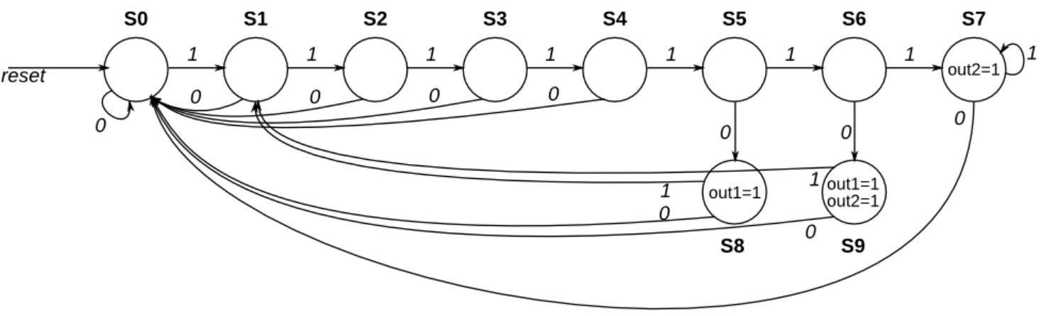
Given the following state machine with 1 input and 2 outputs:
问题示意图(转自HDLBits) -
Code Block
module top_module(
    input in,
    input [9:0] state,
    output [9:0] next_state,
    output out1,
    output out2);

    parameter S0 = 4'd0;
    parameter S1 = 4'd1;
    parameter S2 = 4'd2;
    parameter S3 = 4'd3;
    parameter S4 = 4'd4;
    parameter S5 = 4'd5;
    parameter S6 = 4'd6;
    parameter S7 = 4'd7;
    parameter S8 = 4'd8;
	parameter S9 = 4'd9;

    assign next_state[0] = ~in & (state[S0] | state[S1] | state[S2] | state[S3] | state[S4] | state[S7] | state[S8] | state[S9]);
    assign next_state[1] = in & (state[S0] | state[S8] | state[S9]);
    assign next_state[2] = in & state[S1];
    assign next_state[3] = in & state[S2];
    assign next_state[4] = in & state[S3];
    assign next_state[5] = in & state[S4];
    assign next_state[6] = in & state[S5];
    assign next_state[7] = in & (state[S6] | state[S7]);
    assign next_state[8] = ~in & state[S5];
    assign next_state[9] = ~in & state[S6];

    assign out1 = (state[S8] | state[S9]);
    assign out2 = (state[S7] | state[S9]);

endmodule
PS/2 packet parser
-
Problem Statement
The PS/2 mouse protocol sends messages that are three bytes long. However, within a continuous byte stream, it’s not obvious where messages start and end. The only indication is that the first byte of each three byte message always has
bit[3]=1(but bit[3] of the other two bytes may be 1 or 0 depending on data).We want a finite state machine that will search for message boundaries when given an input byte stream. The algorithm we’ll use is to discard bytes until we see one with
bit[3]=1. We then assume that this is byte 1 of a message, and signal the receipt of a message once all 3 bytes have been received (done). -
Code Block
module top_module(
    input clk,
    input [7:0] in,
    input reset,    // Synchronous reset
    output done); //
	parameter BYTE0=0, BYTE1=1, BYTE2=2, DONE=3;
    reg[1:0] next_state, state;

    // State transition logic (combinational)
    always@(*)	begin
        case(state)
            BYTE0 : begin
                if(in[3])	begin
                    next_state <= BYTE1;
                end
                else	begin
                    next_state <= BYTE0;
                end
            end
            BYTE1 : begin
            	next_state <= BYTE2;
            end
            BYTE2 : begin
            	next_state <= DONE;
            end
            DONE : begin
                if(in[3])	begin
                    next_state <= BYTE1;
                end
                else	begin
                    next_state <= BYTE0;
                end
            end
        endcase
    end
    // State flip-flops (sequential)
    always@(posedge clk)	begin
        if(reset)	begin
            state <= BYTE0;
        end
        else	begin
            state <= next_state;
        end
    end
    // Output logic
    assign done = (state == DONE);

endmodule
PS/2 packet parser and datapath
-
Problem Statement
Now that you have a state machine that will identify three-byte messages in a PS/2 byte stream, add a datapath that will also output the 24-bit (3 byte) message whenever a packet is received (
out_bytes[23:16]is the first byte,out_bytes[15:8]is the second byte, etc.).out_bytesneeds to be valid whenever thedonesignal is asserted. You may output anything at other times (i.e., don’t-care). -
Code Block
module top_module(
    input clk,
    input [7:0] in,
    input reset,    // Synchronous reset
    output [23:0] out_bytes,
    output done); //
	parameter BYTE0=0, BYTE1=1, BYTE2=2, DONE=3;
    reg[1:0] next_state, state;
    reg [23:0] out_bytes_reg;
    // FSM from fsm_ps2
	always@(*)	begin
        case(state)
            BYTE0 : begin
                if(in[3])	begin
                    next_state <= BYTE1;
                end
                else	begin
                    next_state <= BYTE0;
                end
            end
            BYTE1 : begin
            	next_state <= BYTE2;
            end
            BYTE2 : begin
            	next_state <= DONE;
            end
            DONE : begin
                if(in[3])	begin
                    next_state <= BYTE1;
                end
                else	begin
                    next_state <= BYTE0;
                end
            end
        endcase
    end
    always@(posedge clk)	begin
        if(reset)	begin
            state <= BYTE0;
        end
        else	begin
            state <= next_state;
        end
    end
    always @(posedge clk)begin
        if(next_state == BYTE1)begin
            out_bytes_reg[23:16] <= in;
        end
        else if(next_state == BYTE2)begin
            out_bytes_reg[15:8] <= in;
        end
        else if(next_state == DONE)begin
            out_bytes_reg[7:0] <= in;
        end
        else begin
            out_bytes_reg <= 24'd0;
        end
    end

    // New: Datapath to store incoming bytes.
    assign done = (state == DONE);
    assign out_bytes = out_bytes_reg;

endmodule
Serial receiver
-
Problem Statement
In many (older) serial communications protocols, each data byte is sent along with a start bit and a stop bit, to help the receiver delimit bytes from the stream of bits. One common scheme is to use one start bit (0), 8 data bits, and 1 stop bit (1). The line is also at logic 1 when nothing is being transmitted (idle).
Design a finite state machine that will identify when bytes have been correctly received when given a stream of bits. It needs to identify the start bit, wait for all 8 data bits, then verify that the stop bit was correct. If the stop bit does not appear when expected, the FSM must wait until it finds a stop bit before attempting to receive the next byte.
-
Code Block
module top_module( input clk, input in, input reset, // Synchronous reset output done ); parameter [3:0] START = 4'd0, ONE = 4'd1, TWO = 4'd2, THREE = 4'd3, FOUR = 4'd4, FIVE = 4'd5, SIX = 4'd6, SEVEN = 4'd7, EIGHT = 4'd8, STOP = 4'd9, IDLE = 4'd10, WAIT = 4'd11; reg [3:0] state,next_state; always @(*)begin case(state) START:begin next_state <= ONE; end ONE:begin next_state <= TWO; end TWO:begin next_state <= THREE; end THREE:begin next_state <= FOUR; end FOUR:begin next_state <= FIVE; end FIVE:begin next_state <= SIX; end SIX:begin next_state <= SEVEN; end SEVEN:begin next_state <= EIGHT; end EIGHT:begin if(in)begin next_state <= STOP; end else begin next_state <= WAIT; end end STOP:begin if(in)begin next_state <= IDLE; end else begin next_state <= START; end end WAIT:begin if(in)begin next_state <= IDLE; end else begin next_state <= WAIT; end end IDLE:begin if(~in)begin next_state <= START; end else begin next_state <= IDLE; end end endcase end always @(posedge clk)begin if(reset)begin state <= IDLE; end else begin state <= next_state; end end assign done = (state == STOP); endmodule -
Key Point
在实际使用中,数据位不一定只有八位,如果位数更多这么写并不方便,所以我们可以里面使用一个计数器来完成这个工作,代码如下:
module top_module(
    input clk,
    input in,
    input reset,    // Synchronous reset
    output done
);
	parameter IDLE = 3'd0, START = 3'd1, DATA = 3'd2, STOP = 3'd3, WAIT = 3'd4;

    reg [3:0]	state, next_state, counter;
    always @(*)begin
        case(state)
            START:begin
                next_state <= DATA;
            end

            DATA:begin //数据位,通过计数来代替8个数据位。
                if(counter == 4'd8)begin	//传输8位数据后,判断停止位还是等待位。
                    next_state <= in? STOP:WAIT;
                end
                else begin
                    next_state <= DATA;	//传输数据
                end
            end

            STOP:begin
                next_state <= in? IDLE:START;
            end

            WAIT:begin
                next_state <= in? IDLE:WAIT;
            end

            IDLE:begin
                if(~in)begin
                    next_state <= START;
                end
                else begin
                    next_state <= IDLE;
                end
            end
        endcase
    end

    always @(posedge clk)begin
        if(reset)begin
            state <= IDLE;
        end
        else begin
            state <= next_state;
        end
    end

    always @(posedge clk)begin
        if(next_state == DATA)	begin
            counter <= counter + 1'd1;
        end
        else	begin
            counter <= 4'd0;
        end
    end

	assign done = (state == STOP);
endmodule
Serial receiver and datapath
-
Problem Statement
Now that you have a finite state machine that can identify when bytes are correctly received in a serial bitstream, add a datapath that will output the correctly-received data byte.
out_byteneeds to be valid whendoneis1, and is don’t-care otherwise.Note that the serial protocol sends the least significant bit first.
-
Code Block
module top_module( input clk, input in, input reset, // Synchronous reset output [7:0] out_byte, output done ); // // Use FSM from Fsm_serial parameter [3:0] START = 4'd0, ONE = 4'd1, TWO = 4'd2, THREE = 4'd3, FOUR = 4'd4, FIVE = 4'd5, SIX = 4'd6, SEVEN = 4'd7, EIGHT = 4'd8, STOP = 4'd9, IDLE = 4'd10, WAIT = 4'd11; reg [3:0] state,next_state; reg [7:0] temp_in; always @(*)begin case(state) START:begin next_state <= ONE; temp_in[0] <= in; end ONE:begin next_state <= TWO; temp_in[1] <= in; end TWO:begin next_state <= THREE; temp_in[2] <= in; end THREE:begin next_state <= FOUR; temp_in[3] <= in; end FOUR:begin next_state <= FIVE; temp_in[4] <= in; end FIVE:begin next_state <= SIX; temp_in[5] <= in; end SIX:begin next_state <= SEVEN; temp_in[6] <= in; end SEVEN:begin next_state <= EIGHT; temp_in[7] <= in; end EIGHT:begin if(in)begin next_state <= STOP; end else begin next_state <= WAIT; end end STOP:begin if(in)begin next_state <= IDLE; end else begin next_state <= START; end end WAIT:begin if(in)begin next_state <= IDLE; end else begin next_state <= WAIT; end end IDLE:begin if(~in)begin next_state <= START; end else begin next_state <= IDLE; end end endcase end always @(posedge clk)begin if(reset)begin state <= IDLE; end else begin state <= next_state; end end assign done = (state == STOP); // New: Datapath to latch input bits. assign out_byte = (state == STOP) ? temp_in : 8'd0; endmodule -
Key Point
同理,我们依旧可以按照上一点的第二种方法来写这个题,代码如下:
module top_module(
    input clk,
    input in,
    input reset,    // Synchronous reset
    output [7:0] out_byte,
    output done
); //
	parameter IDLE = 3'd0, START = 3'd1, DATA = 3'd2, STOP = 3'd3, WAIT = 3'd4;
    reg [3:0]	state, next_state, counter;
    reg [7:0]	temp_in;
    always @(*)begin
        case(state)
            START:begin
                next_state <= DATA;
            end

            DATA:begin //数据位,通过计数来代替8个数据位。
                if(counter == 4'd8)begin	//传输8位数据后,判断停止位还是等待位。
                    next_state <= in? STOP:WAIT;
                end
                else begin
                    next_state <= DATA;	//传输数据
                end
            end

            STOP:begin
                next_state <= in? IDLE:START;
            end

            WAIT:begin
                next_state <= in? IDLE:WAIT;
            end

            IDLE:begin
                if(~in)begin
                    next_state <= START;
                end
                else begin
                    next_state <= IDLE;
                end
            end
        endcase
    end

    always @(posedge clk)begin
        if(reset)begin
            state <= IDLE;
        end
        else begin
            state <= next_state;
        end
    end

    always @(posedge clk)begin
        if(next_state == DATA)	begin
            counter <= counter + 1'd1;
            temp_in[counter] <= in;
        end
        else	begin
            counter <= 4'd0;
        end
    end

	assign done = (state == STOP);
    assign out_byte = (state == STOP) ? temp_in : 8'd0;

endmodule
Serial receiver with parity checking
-
Problem Statement
We want to add parity checking to the serial receiver. Parity checking adds one extra bit after each data byte. We will use odd parity, where the number of
1s in the 9 bits received must be odd. For example,101001011satisfies odd parity (there are 51s), but001001011does not.You are provided with the following module that can be used to calculate the parity of the input stream (It’s a TFF with reset). The intended use is that it should be given the input bit stream, and reset at appropriate times so it counts the number of
1bits in each byte.module parity ( input clk, input reset, input in, output reg odd); always @(posedge clk) if (reset) odd <= 0; else if (in) odd <= ~odd; endmodule -
Code Block
module top_module(
    input clk,
    input in,
    input reset,    // Synchronous reset
    output [7:0] out_byte,
    output done
); //

    parameter IDLE = 3'd0,START = 3'd1,DATA = 3'd2;
    parameter STOP = 3'd3,WAIT = 3'd4;

    reg [2:0] state,next_state;
    reg [3:0] counter;
    reg [8:0] temp_in;
    reg temp_odd;
    wire reset_odd;

    // Modify FSM and datapath from Fsm_serialdata
    always @(*)begin
        case(state)
            START:begin
                next_state <= DATA;
            end

            DATA:begin //数据位,通过计数来代替8个数据位。
                if(counter == 4'd9)begin	//传输8位数据后,判断停止位还是等待位。
                    next_state <= in? STOP:WAIT;
                end
                else begin
                    next_state <= DATA;	//传输数据
                end
            end

            STOP:begin
                next_state <= in? IDLE:START;
            end

            WAIT:begin
                next_state <= in? IDLE:WAIT;
            end

            IDLE:begin
                if(in)begin
                    next_state <= IDLE;
                end
                else begin
                    next_state <= START;
                end
            end

        endcase
    end

    always @(posedge clk) begin
        if(reset)begin
            state <= IDLE;
        end
        else begin
            state <= next_state;
        end
    end

    always @(posedge clk) begin
        if(reset)begin
            done <= 1'd0;
            out_byte <= 8'd0;
            counter <= 4'd0;
        end
        else begin
            case(next_state)
                DATA:begin
                    done <= 1'd0;
                    out_byte <= 8'd0;
                    counter <= counter + 1'd1;
                    temp_in[counter] <= in;
                end
                STOP:begin
                    done <= temp_odd ? 1'd1 : 1'd0;
                    out_byte <= temp_odd ? temp_in[7:0] : 8'd0;
                    counter <= 4'd0;
                end
                default : begin
                    done <= 1'd0;
                    out_byte <= 8'd0;
                    counter <= 4'd0;
                end
            endcase
        end
    end

    assign reset_odd = (next_state == START);
    parity u0(clk,reset_odd,in,temp_odd);

endmodule
Sequence recognition
-
Problem Statement
Synchronous HDLC framing involves decoding a continuous bit stream of data to look for bit patterns that indicate the beginning and end of frames (packets). Seeing exactly 6 consecutive 1s (i.e., 01111110) is a “flag” that indicate frame boundaries. To avoid the data stream from accidentally containing “flags”, the sender inserts a zero after every 5 consecutive 1s which the receiver must detect and discard. We also need to signal an error if there are 7 or more consecutive 1s.
Create a finite state machine to recognize these three sequences:
0111110: Signal a bit needs to be discarded (disc).
01111110: Flag the beginning/end of a frame (flag).
01111111…: Error (7 or more 1s) (err).
When the FSM is reset, it should be in a state that behaves as though the previous input were 0. -
Code Block
module top_module(
    input clk,
    input reset,    // Synchronous reset
    input in,
    output disc,
    output flag,
    output err);
    parameter NONE=0, ONE=1, TWO=2, THREE=3, FOUR=4, FIVE=5, SIX=6, DISCARD=7, FLAG=8, ERROR=9;
    reg[3:0]	state, next_state;
    always@(*)	begin
        case(state)
            NONE : begin
                if(in)	begin
                    next_state <= ONE;
                end
                else	begin
                    next_state <= NONE;
                end
            end
            ONE : begin
                if(in)	begin
                    next_state <= TWO;
                end
                else	begin
                    next_state <= NONE;
                end
            end
            TWO : begin
                if(in)	begin
                    next_state <= THREE;
                end
                else	begin
                    next_state <= NONE;
                end
            end
            THREE : begin
                if(in)	begin
                    next_state <= FOUR;
                end
                else	begin
                    next_state <= NONE;
                end
            end
            FOUR : begin
                if(in)	begin
                    next_state <= FIVE;
                end
                else	begin
                    next_state <= NONE;
                end
            end
            FIVE : begin
                if(in)	begin
                    next_state <= SIX;
                end
                else	begin
                    next_state <= DISCARD;
                end
            end
            SIX : begin
                if(in)	begin
                    next_state <= ERROR;
                end
                else	begin
                    next_state <= FLAG;
                end
            end
            DISCARD : begin
                if(in)	begin
                    next_state <= ONE;
                end
                else	begin
                    next_state <= NONE;
                end
            end
            FLAG : begin
                if(in)	begin
                    next_state <= ONE;
                end
                else	begin
                    next_state <= NONE;
                end
            end
            ERROR : begin
                if(in)	begin
                    next_state <= ERROR;
                end
                else	begin
                    next_state <= NONE;
                end
            end
        endcase
    end

    always@(posedge clk)	begin
        if(reset)	begin
            state <= NONE;
        end
        else	begin
            state <= next_state;
        end
    end
    assign err  = (state == ERROR);
    assign flag = (state == FLAG);
    assign disc = (state == DISCARD);

endmodule
Q8:Design a Mealy FSM
-
Problem Statement
Implement a Mealy-type finite state machine that recognizes the sequence “101” on an input signal named x. Your FSM should have an output signal, z, that is asserted to logic-1 when the “101” sequence is detected. Your FSM should also have an active-low asynchronous reset. You may only have 3 states in your state machine. Your FSM should recognize overlapping sequences.
-
Code Block
module top_module (
    input clk,
    input aresetn,    // Asynchronous active-low reset
    input x,
    output z );
    parameter S0=0, S1=1, S2=2;//题目要求只用三个状态解决问题。
    reg[2:0] state, next_state;
    always@(*)	begin
        case(state)
            S0 :	begin
                next_state <= x ? S1:S0;	//检测第一位,输入是1是跳到S1,不然留在S0。
            end
            S1 :	begin
                next_state <= (~x) ?  S2:S1;	//检测第二位,输入为0则跳到S2,输入为1时,保持不变,不然当输入为'1101'时,无法检测。
            end
            S2 :	begin
                next_state <= x ? S1:S0;	//检测第三位,输入为1时跳到S1,作交叠检测,既当'10101'时,在第三位和第五位Z输出为1。
            end
        endcase
    end
    always @(posedge clk or negedge aresetn)	begin
        if(~aresetn)	begin	//异步低电平复位
            state <= S0;
        end
        else	begin
            state <= next_state;
        end
    end
    //assign z = (state == S2)? x : 1'b0;
	always @(*) begin
        z = (state == S2) ? x : 1'b0;
    end
endmodule
Q5a:Serial two’s complementer(Moore FSM)
-
Problem Statement
You are to design a one-input one-output serial 2’s complementer Moore state machine. The input (x) is a series of bits (one per clock cycle) beginning with the least-significant bit of the number, and the output (Z) is the 2’s complement of the input. The machine will accept input numbers of arbitrary length. The circuit requires an asynchronous reset. The conversion begins when Reset is released and stops when Reset is asserted.
-
Code Block
module top_module ( input clk, input areset, input x, output z ); parameter S0 = 2'd0, S1 = 2'd1, S2 = 2'd2; reg [1:0] state, next_state; always @(*) begin case(state)//~x代表x取反后状态 S0: next_state = (~x) ? S0 : S1;//若取反后,低位均为1,则加1以后一直向前进位,并且从1转0 //故~x为1,保持S0状态,则表示取反后等于1,并且进位后又变为0。 //若~x为0,则S0状态进为S1状态,该位加1并不需要向上进位。 S1: next_state = (~x) ? S1 : S2;//S1和S2只是保存对x的取反结果即可。 S2: next_state = (~x) ? S1 : S2; endcase end always @(posedge clk or posedge areset) begin if(areset)begin state <= S0; end else begin state <= next_state; end end assign z = (state == S1); endmodule -
Key Point
题目的要求是任意长度输入取补码,我们用状态机实现输入取反后的加一,解决进位的问题。
Q5b: Serial two’s complementer(Mealy FSM)
-
Problem Statement
The following diagram is a Mealy machine implementation of the 2’s complementer. Implement using one-hot encoding.
-
Code Block
module top_module (
    input clk,
    input areset,
    input x,
    output z
);
    parameter A = 1'b0, B = 1'b1;
    reg state,next_state;
    always@(*)	begin
        case(state)
            A : next_state <= x ? B : A;
            B : next_state <= B;
        endcase
    end
    always@(posedge clk or posedge areset)	begin
        if(areset)	begin
            state <= A;
        end
        else	begin
            state <= next_state;
        end
    end
    assign z = ((state == A) && x) || ((state == B) && (~x));
endmodule
Q3a:FSM
-
Problem Statement
-
Code Block
module top_module (
    input clk,
    input reset,   // Synchronous reset
    input s,
    input w,
    output z
);
    parameter A = 1'd0, B = 1'd1;
    reg state, next_state;
    reg [1:0] counter,w_counter;

    always@(*)	begin
        case(state)
            A : next_state <= s ? B:A;
            B : next_state <= B;
            default next_state <= A;
        endcase
    end

    always @(posedge clk) begin
        if(reset)begin
            state <= A;
        end
        else begin
            state <= next_state;
        end
    end

    always @(posedge clk) begin
        if(reset)begin
            counter <= 2'd0;
        end
        else if(counter == 2'd2) begin
            counter <= 2'd0;
        end
        else if(state == B)	     begin//W计数3个周期
            counter <= counter + 1'd1;
        end

    end

    always@(posedge clk)	begin
        if(reset)	begin
            w_counter <= 1'b0;
        end
        else if(counter == 2'b0) begin	//当counter=0时是新周期的开始,判断要置0还是加1。
            w_counter <= w;
        end
        else if(state == B)	begin
            w_counter <= w_counter + w;
        end
    end

    assign z = (state == B && w_counter == 2'd2 && counter == 2'd0);
endmodule
Q3b:FSM
-
Problem Statement
Given the state-assigned table shown below, implement the finite-state machine. Reset should reset the FSM to state 000.
问题示意图(转自HDLBits) -
Code Block
module top_module (
    input clk,
    input reset,   // Synchronous reset
    input x,
    output z
);
    parameter S0=0, S1=1, S2=2, S3=3, S4=4;
    reg [2:0] state, next_state;
    always@(*)	begin
        case(state)
        S0 :	next_state <= x ? S1:S0;
        S1 :	next_state <= x ? S4:S1;
        S2 :	next_state <= x ? S1:S2;
        S3 :	next_state <= x ? S2:S1;
        S4 :	next_state <= x ? S4:S3;
        endcase
    end
    always@(posedge clk)	begin
        if(reset)	begin
            state <= S0;
        end
        else	begin
            state <= next_state;
        end
    end
    assign z = (state == S3) | (state == S4);
endmodule
Q3c:FSM logic
-
Problem Statement
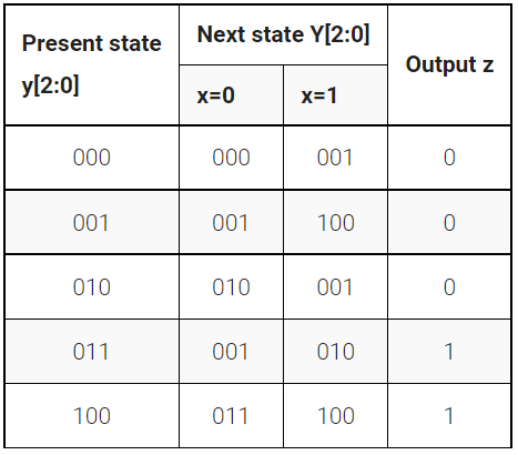
Given the state-assigned table shown below, implement the logic functions Y[0] and z.
-
Code Block
module top_module (
    input clk,
    input [2:0] y,
    input x,
    output Y0,
    output z
);
    assign Y0 = (y[0]&(~x)) | ( (~y[0]) & (y[2]^x) );
    assign z  = (y == 3'b011) | (y == 3'b100);
endmodule
Q6b: FSM next-state logic
-
Problem Statement
Consider the state machine shown below, which has one input w and one output z.
问题示意图(转自HDLBits) -
Code Block
module top_module (
    input [3:1] y,
    input w,
    output Y2);
    assign Y2 = (y == 3'b001) | (y==3'b101) | ((y==3'b100 | y==3'b010) & w);

endmodule
Q6b: FSM one-hot next-state logic
-
Problem statement
For this part, assume that a one-hot code is used with the state assignment 'y[6:1] = 000001, 000010, 000100, 001000, 010000, 100000 for states A, B,…, F, respectively.
Write a logic expression for the next-state signals Y2 and Y4. (Derive the logic equations by inspection assuming a one-hot encoding. The testbench will test with non-one hot inputs to make sure you’re not trying to do something more complicated).
-
Code Block
module top_module (
    input [6:1] y,
    input w,
    output Y2,
    output Y4);
	assign Y2 = ~w & y[1];
    assign Y4 = (w & y[2])|(w & y[3])|(w & y[5])|(w & y[6]);
endmodule
Q6:FSM
-
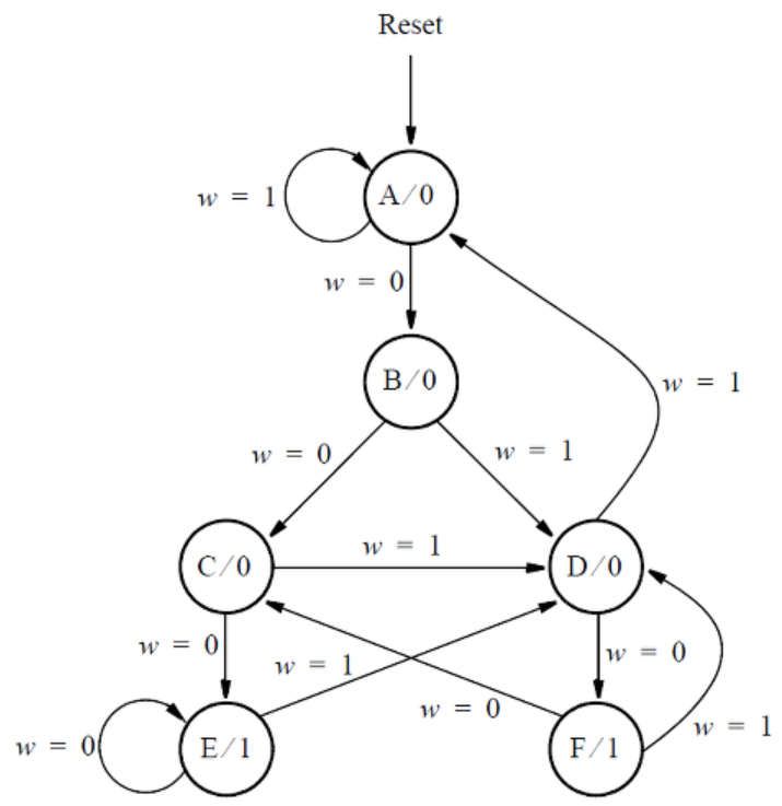
Problem Statement
Consider the state machine shown below, which has one input w and one output z.
-
Code Block
module top_module (
    input clk,
    input reset,     // synchronous reset
    input w,
    output z);

    parameter A = 0, B = 1, C=2, D = 3, E = 4, F = 5;
    reg [2:0] state, next_state;

    always @(*) begin
        case(state)
            A:      next_state = w ? A : B;
            B:      next_state = w ? D : C;
            C:      next_state = w ? D : E;
            D:      next_state = w ? A : F;
            E:      next_state = w ? D : E;
            F:      next_state = w ? D : C;
            default:next_state = A;
        endcase
    end

    always @(posedge clk) begin
        if(reset)begin
            state <= A;
        end
        else begin
            state <= next_state;
        end
    end
    assign z = (state == E | state == F);
endmodule
Q2a: FSM
-
Problem Statement
Write complete Verilog code that represents this FSM. Use separate always blocks for the state table and the state flip-flops, as done in lectures. Describe the FSM output, which is called z, using either continuous assignment statement(s) or an always block (at your discretion). Assign any state codes that you wish to use.
-
Code Block
module top_module (
    input clk,
    input reset,   // Synchronous active-high reset
    input w,
    output z
);

    parameter A = 0, B = 1, C = 2, D = 3, E = 4, F = 5;
    reg [2:0] state, next_state;

    always @(*) begin
        case(state)
            A:      next_state = w ? B : A;
            B:      next_state = w ? C : D;
            C:      next_state = w ? E : D;
            D:      next_state = w ? F : A;
            E:      next_state = w ? E : D;
            F:      next_state = w ? C : D;
            default:next_state = A;
        endcase
    end

    always @(posedge clk) begin
        if(reset) begin
            state <= A;
        end
        else begin
            state <= next_state;
        end
    end

    assign z = (state == E) | (state == F);

endmodule
Q2b: One-hot FSM equations
-
Problem Statement
Assume that a one-hot code is used with the state assignment y[5:0] = 000001(A), 000010(B), 000100©, 001000(D), 010000(E), 100000(F)
Write a logic expression for the signal Y1, which is the input of state flip-flop y[1].
Write a logic expression for the signal Y3, which is the input of state flip-flop y[3].
(Derive the logic equations by inspection assuming a one-hot encoding. The testbench will test with non-one hot inputs to make sure you’re not trying to do something more complicated).
-
Code Block
module top_module (
    input [5:0] y,
    input w,
    output Y1,
    output Y3
);
    assign Y1 = y[0] & w;
    assign Y3 = (y[1] | y[2] | y[4] | y[5]) & (~w);
endmodule
Q2a:FSM
-
Problem Statement
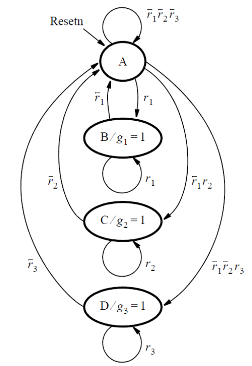
Consider the FSM described by the state diagram shown below:
-
Code Block
module top_module (
    input clk,
    input resetn,    // active-low synchronous reset
    input [3:1] r,   // request
    output [3:1] g   // grant
);
    parameter A=0, B=1, C=2, D=3;
    reg [1:0]	state,next_state;

    always@(*)	begin
        case(state)
            A : begin
                if(r[1])	begin
                    next_state <= B;
                end
                else if(r[2])	begin
                    next_state <= C;
                end
                else if(r[3])	begin
                    next_state <= D;
                end
                else	begin
                    next_state <= A;
                end
            end
            B : begin
                next_state <= r[1] ? B:A;
            end
            C : begin
                next_state <= r[2] ? C:A;
            end
            D : begin
                next_state <= r[3] ? D:A;
            end
            default : next_state <= A;
        endcase
    end
    always@(posedge clk)	begin
        if(~resetn)	begin
            state <= A;
        end
        else	begin
            state <= next_state;
        end
    end

    assign g[1] = state == B;
    assign g[2] = state == C;
    assign g[3] = state == D;

endmodule
Q2b: Another FSM
-
Problem Statement
Consider a finite state machine that is used to control some type of motor. The FSM has inputs x and y, which come from the motor, and produces outputs f and g, which control the motor. There is also a clock input called clk and a reset input called resetn.
The FSM has to work as follows. As long as the reset input is asserted, the FSM stays in a beginning state, called state A. When the reset signal is de-asserted, then after the next clock edge the FSM has to set the output f to 1 for one clock cycle. Then, the FSM has to monitor the x input. When x has produced the values 1, 0, 1 in three successive clock cycles, then g should be set to 1 on the following clock cycle. While maintaining g = 1 the FSM has to monitor the y input. If y has the value 1 within at most two clock cycles, then the FSM should maintain g = 1 permanently (that is, until reset). But if y does not become 1 within two clock cycles, then the FSM should set g = 0 permanently (until reset).
-
Code Block
module top_module (
    input clk,
    input resetn,    // active-low synchronous reset
    input x,
    input y,
    output f,
    output g
);
    parameter  F = 0, S1 = 1, S2 = 2, S3 = 3, S4 = 4, S5 = 5, IDLE = 6, G_ONE = 7, G_ZERO = 8 ;
    reg [3:0] state, next_state;
    always@(*)	begin
        case(state)
            F  : next_state <= S1;
            S1 : next_state <= x ? S2:S1;
            S2 : next_state <= x ? S2:S3;
            S3 : next_state <= x ? S4:S1;
            S4 : next_state <= y ? G_ONE:S5;
            S5 : next_state <= y ? G_ONE:G_ZERO;
            IDLE : next_state <= F;
            G_ONE  : next_state <= G_ONE;
            G_ZERO : next_state <= G_ZERO;
        endcase
    end
    always @(posedge clk) begin
        if(~resetn) begin
            state <= IDLE;
        end
        else begin
            state <= next_state;
        end
    end
    assign f = (state == F);
    assign g = (state == S4) | (state == S5) | (state == G_ONE);
endmodule
Buliding Larger Circuits
Counter with period 1000
-
Problem Statement
Build a counter that counts from 0 to 999, inclusive, with a period of 1000 cycles. The reset input is synchronous, and should reset the counter to 0.
-
Code Block
module top_module (
    input clk,
    input reset,
    output [9:0] q);
    always@(posedge clk)	begin
        if(reset)	begin
            q <= 10'b0;
        end
        else if(q >= 10'd999)	begin
            q <= 10'b0;
        end
        else begin
            q <= q + 1'b1;
        end
    end
endmodule
4-bits shift rigister and down counter
-
Problem Statement
Build a four-bit shift register that also acts as a down counter. Data is shifted in most-significant-bit first when
shift_enais 1. The number currently in the shift register is decremented whencount_enais 1. Since the full system doesn’t ever useshift_enaandcount_enatogether, it does not matter what your circuit does if both control inputs are 1 (This mainly means that it doesn’t matter which case gets higher priority). -
Code Block
module top_module (
    input clk,
    input shift_ena,
    input count_ena,
    input data,
    output [3:0] q);

    always@(posedge clk)	begin
        if(shift_ena)	begin //移位使能端置1以后,第一位变data。
            q <= {q[2:0], data};
        end
        else if(count_ena & q == 4'b0)	begin
            q <= 4'd15;//题目设定0以后就跳回15。
        end
        else if(count_ena)	begin
            q <= q - 1'b1;
        end
    end
endmodule
FSM:Sequence 1101 recognizer
-
Problem Statement
Build a finite-state machine that searches for the sequence 1101 in an input bit stream. When the sequence is found, it should set
start_shiftingto 1, forever, until reset. Getting stuck in the final state is intended to model going to other states in a bigger FSM that is not yet implemented. We will be extending this FSM in the next few exercises. -
Code Block
module top_module (
    input clk,
    input reset,      // Synchronous reset
    input data,
    output start_shifting);
    parameter IDLE=0, S1=1, S2=2, S3=3, STUCK=4;
    reg [2:0] state, next_state;
    always@(*)	begin
        case(state)
            IDLE : next_state <= data ? S1 : IDLE;
            S1 : next_state <= data ? S2 : IDLE;
            S2 : next_state <= data ? S2 : S3;
            S3 : next_state <= data ? STUCK : IDLE;
            STUCK : next_state <= STUCK;
            default:    next_state <= IDLE;
        endcase
    end

    always @(posedge clk) begin
        if(reset) begin
            state <= IDLE;
        end
        else begin
            state <= next_state;
        end
    end

    assign start_shifting = (state == STUCK);
endmodule
FSM: Enable shift register
-
Problem Statement
As part of the FSM for controlling the shift register, we want the ability to enable the shift register for exactly 4 clock cycles whenever the proper bit pattern is detected. We handle sequence detection in Exams/review2015_fsmseq, so this portion of the FSM only handles enabling the shift register for 4 cycles.
-
Code Block
module top_module (
    input clk,
    input reset,      // Synchronous reset
    output shift_ena);
    parameter IDLE=0, CLOCK=1, STUCK=2;
    reg [1:0] state, next_state;
    reg [2:0] clock_counter;

    always@(*)	begin
        case(state)
            IDLE  : next_state <= CLOCK;
            CLOCK : next_state <= (clock_counter >= 3'd2) ? STUCK : CLOCK;
            STUCK : next_state <= STUCK;
            default:    next_state = IDLE;
        endcase
    end
    always@(posedge clk)	begin
        if (reset)	begin
            state <= IDLE;
        end
        else begin
            state <= next_state;
        end
    end
    always@(posedge clk)	begin
        if(reset)	begin
            clock_counter <= 3'b0;
        end
        if(state == CLOCK)	begin
            clock_counter <= clock_counter + 1'b1;
        end
        else	begin
            clock_counter <= 3'b0;
        end
    end
    assign shift_ena = (state == CLOCK) | (state == IDLE);
endmodule
FSM: The complete FSM
-
Problem Statement
We want to create a timer that:
- is started when a particular pattern (1101) is detected,
- shifts in 4 more bits to determine the duration to delay,
- waits for the counters to finish counting, and
- notifies the user and waits for the user to acknowledge the timer.
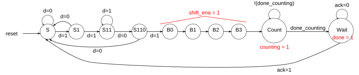
In this problem, implement just the finite-state machine that controls the timer. The data path (counters and some comparators) are not included here.
The serial data is available on the
datainput pin. When the pattern 1101 is received, the state machine must then assert outputshift_enafor exactly 4 clock cycles.After that, the state machine asserts its
countingoutput to indicate it is waiting for the counters, and waits until inputdone_countingis high.At that point, the state machine must assert
doneto notify the user the timer has timed out, and waits until inputackis 1 before being reset to look for the next occurrence of the start sequence (1101).The state machine should reset into a state where it begins searching for the input sequence 1101.
Here is an example of the expected inputs and outputs. The ‘x’ states may be slightly confusing to read. They indicate that the FSM should not care about that particular input signal in that cycle. For example, once a 1101 pattern is detected, the FSM no longer looks at the
datainput until it resumes searching after everything else is done. -
Code Block
module top_module (
    input clk,
    input reset,      // Synchronous reset
    input data,
    output shift_ena,
    output counting,
    input done_counting,
    output done,
    input ack );
    parameter S0=0, S1=1, S2=2, S3=3, SHIFT=4, COUNT=5, WAIT=6;
    reg [3:0] state, next_state;
    reg [2:0] clock_counter;

    always@(*)	begin
        case(state)
            S0 : next_state <= data ? S1:S0;
            S1 : next_state <= data ? S2:S0;
            S2 : next_state <= data ? S2:S3;
            S3 : next_state <= data ? SHIFT:S0;
            SHIFT : next_state <= (clock_counter >= 3'd3) ? COUNT : SHIFT;
            COUNT : next_state <= done_counting ? WAIT: COUNT;
            WAIT  : next_state <= ack ? S0:WAIT;
        endcase
    end
    always@(posedge clk)	begin
        if(reset)	begin
            state <= S0;
        end
        else	begin
            state <= next_state;
        end
    end
    always@(posedge clk)	begin
        if(reset)	begin
            clock_counter <= 3'b0;
        end
        if(state == SHIFT)	begin
            clock_counter <= clock_counter + 1'b1;
        end
        else	begin
            clock_counter <= 3'b0;
        end
    end
    assign shift_ena = (state == SHIFT);
    assign counting = (state == COUNT);
    assign done = (state == WAIT);

endmodule
The complete timer
-
Problem Statement
We want to create a timer with one input that:
- is started when a particular input pattern (1101) is detected,
- shifts in 4 more bits to determine the duration to delay,
- waits for the counters to finish counting, and
- notifies the user and waits for the user to acknowledge the timer.
The serial data is available on the
datainput pin. When the pattern 1101 is received, the circuit must then shift in the next 4 bits, most-significant-bit first. These 4 bits determine the duration of the timer delay. I’ll refer to this as thedelay[3:0].After that, the state machine asserts its
countingoutput to indicate it is counting. The state machine must count for exactly(delay[3:0] + 1) * 1000clock cycles. e.g., delay=0 means count 1000 cycles, and delay=5 means count 6000 cycles. Also output the current remaining time. This should be equal todelayfor 1000 cycles, thendelay-1for 1000 cycles, and so on until it is 0 for 1000 cycles. When the circuit isn’t counting, the count[3:0] output is don’t-care (whatever value is convenient for you to implement).At that point, the circuit must assert
doneto notify the user the timer has timed out, and waits until inputackis 1 before being reset to look for the next occurrence of the start sequence (1101).The circuit should reset into a state where it begins searching for the input sequence 1101.
Here is an example of the expected inputs and outputs. The ‘x’ states may be slightly confusing to read. They indicate that the FSM should not care about that particular input signal in that cycle. For example, once the 1101 and delay[3:0] have been read, the circuit no longer looks at the
datainput until it resumes searching after everything else is done. In this example, the circuit counts for 2000 clock cycles because the delay[3:0] value was 4’b0001. The last few cycles starts another count with delay[3:0] = 4’b1110, which will count for 15000 cycles. -
Code Block
module top_module (
    input clk,
    input reset,      // Synchronous reset
    input data,
    output [3:0] count,
    output counting,
    output done,
    input ack );

    parameter S=0, S1=1, S11=2, S110=3, B0=4, B1=5, B2=6, B3=7, COUNT_REG=8, WAIT=9;
    reg [3:0]	state;
    reg [3:0]	next_state;
    reg [3:0]	par_in;

    reg [15:0]	counter;
    always@(posedge clk)begin
        if(reset)begin
            counter <= 16'd0;
        end
        else if(next_state == WAIT)begin
            counter <= 16'd0;
        end
        else if(next_state == COUNT_REG)begin
            counter <= counter + 1'b1;
        end
    end

    reg [3:0]	a;
    always@(*)begin
        if(counter <= 1000)begin
            a = 4'd0;
        end
        else if(counter > 1000 && counter <= 2000)begin
            a = 4'd1;
        end
        else if(counter > 2000 && counter <= 3000)begin
            a = 4'd2;
        end
        else if(counter > 3000 && counter <= 4000)begin
            a = 4'd3;
        end
        else if(counter > 4000 && counter <= 5000)begin
            a = 4'd4;
        end
        else if(counter > 5000 && counter <= 6000)begin
            a = 4'd5;
        end
        else if(counter > 6000 && counter <= 7000)begin
            a = 4'd6;
        end
        else if(counter > 7000 && counter <= 8000)begin
            a = 4'd7;
        end
        else if(counter > 8000 && counter <= 9000)begin
            a = 4'd8;
        end
        else if(counter > 9000 && counter <= 10000)begin
            a = 4'd9;
        end
        else if(counter > 10000 && counter <= 11000)begin
            a = 4'd10;
        end
        else if(counter > 11000 && counter <= 12000)begin
            a = 4'd11;
        end
        else if(counter > 12000 && counter <= 13000)begin
            a = 4'd12;
        end
        else if(counter > 13000 && counter <= 14000)begin
            a = 4'd13;
        end
        else if(counter > 14000 && counter <= 15000)begin
            a = 4'd14;
        end
        else begin
            a = 4'd15;
        end
    end

    wire b;
    assign b = (counter == (par_in + 1) * 1000) ? 1'b1 : 1'b0;

    always@(posedge clk)begin
        if(reset)begin
            state <= S;
        end
        else begin
            state <= next_state;
        end
    end

    always@(*)begin
        case(state)
            S:begin
                next_state = data ? S1 : S;
            end
            S1:begin
                next_state = data ? S11 : S;
            end
            S11:begin
                next_state = data ? S11 : S110;
            end
            S110:begin
                next_state = data ? B0 : S;
            end
            B0:begin
                next_state = B1;
                par_in[3] = data;
            end
            B1:begin
                next_state = B2;
                par_in[2] = data;
            end
            B2:begin
                next_state = B3;
                par_in[1] = data;
            end
            B3:begin
                next_state = COUNT_REG;
                par_in[0] = data;
            end
            COUNT_REG:begin
                next_state = b ? WAIT : COUNT_REG;
            end
            WAIT:begin
                next_state = ack ? S : WAIT;
            end
            default:begin
                next_state = S;
            end
        endcase
    end

    assign count = (state == COUNT_REG) ? (par_in - a) : 4'd0;
    assign counting = (state == COUNT_REG);
    assign done = (state == WAIT);

endmodule
FSM: One-hot logic equations
-
Problem Statement
Derive next-state logic equations and output logic equations by inspection assuming the following one-hot encoding is used:
(S, S1, S11, S110, B0, B1, B2, B3, Count, Wait) = (10'b0000000001, 10'b0000000010, 10'b0000000100, ... , 10'b1000000000)Derive state transition and output logic equations by inspection assuming a one-hot encoding. Implement only the state transition logic and output logic (the combinational logic portion) for this state machine. (The testbench will test with non-one hot inputs to make sure you’re not trying to do something more complicated).
Write code that generates the following equations:
- B3_next – next-state logic for state B1
- S_next
- S1_next
- Count_next
- Wait_next
- done – output logic
- counting
- shift_ena
问题示意图(转自HDLBits) -
Code Block
module top_module(
    input d,
    input done_counting,
    input ack,
    input [9:0] state,    // 10-bit one-hot current state
    output B3_next,
    output S_next,
    output S1_next,
    output Count_next,
    output Wait_next,
    output done,
    output counting,
    output shift_ena
); //

    // You may use these parameters to access state bits using e.g., state[B2] instead of state[6].
    parameter S=0, S1=1, S11=2, S110=3, B0=4, B1=5, B2=6, B3=7, Count=8, Wait=9;

    assign B3_next = state[B2];
    assign S_next  = ( (state[S] | state[S1] | state[S110]) & (~d)) | (state[Wait] & ack);
    assign S1_next = state[S] & d;
    assign Count_next = state[B3] | ( (~done_counting) & state[Count]);
    assign Wait_next = (done_counting & state[Count]) | (state[Wait] & (~ack) );
    assign done = state[Wait];
    assign counting = state[Count];
    assign shift_ena = state[B0] | state[B1] | state[B2] | state[B3];

endmodule


 219
219


 被折叠的 条评论
为什么被折叠?
被折叠的 条评论
为什么被折叠?
 到【灌水乐园】发言


