


代码工程地址:
https://github.com/jiabaodan/Direct12BookReadingNotes
学习目标
- 学习如何实现硬件实例化;
- 熟悉包围体,学习如何创建和使用它们;
- 学习如何实现截头锥体剔除。
1 硬件实例化
给每个实例都复制一份顶点和索引是非常浪费的,所以我们只保存一份物体在局部坐标系下的数据,然后使用不同的世界变换矩阵和材质绘制它多次。
虽然这个策略节约了内存,但它需要逐物体的API开销(对每个物体我们需要设置它的世界变换矩阵,材质和调用绘制命令)。即使D3D12已经重新设计和最小化了D3D11里在绘制调用时候的API开销,但是还是会有一些开销。D3D的实例化API可以让你绘制一个物体多次,但是只需要一个绘制调用;并且使用动态索引,实例化在D3D11中变得更加灵活。
绘制调用(Draw Call)造成的性能开销是CPU的瓶颈(不是GPU),因为每次绘制调用,CPU需要做很多状态改变。图形引擎采用批处理技术([Wloka03])来减少绘制调用,硬件实例化就是达成批处理的一方面方案。
1.1 绘制实例数据
在之前的章节,我们已经使用实例化技术,只不过每次只实例化1个:
cmdList->DrawIndexedInstanced(ri->IndexCount,
	1,
	ri->StartIndexLocation, ri->BaseVertexLocation, 0);
第二个参数就是实例化的个数。
1.2 实例数据
本书的之前的版本包含了一个方法,将实例数据通过IA阶段输入。当创建一个输入布局的时候可以通过D3D12_INPUT_CLASSIFICATION_PER_INSTANCE_DATA指定一个针对每个实例的数据流,而不是针对每个顶点列表的D3D12_INPUT_CLASSIFICATION_PER_VERTEX_DATA。D3D12依然支持这种方法,但是这次我们会介绍一个更高级的方法。
这个方法就是创建一个结构化缓冲好包含所有需要的实例数据;然后绑定这个结构化缓冲到渲染流水线。然后通过一个系统值SV_InstanceID在着色器代码中索引:
// Defaults for number of lights.
#ifndef NUM_DIR_LIGHTS
	#define NUM_DIR_LIGHTS 3
#endif
#ifndef NUM_POINT_LIGHTS
	#define NUM_POINT_LIGHTS 0
#endif
#ifndef NUM_SPOT_LIGHTS
	#define NUM_SPOT_LIGHTS 0
#endif

// Include structures and functions for lighting.
#include "LightingUtil.hlsl"

struct InstanceData
{
	float4x4 World;
	float4x4 TexTransform;
	uint MaterialIndex;
	uint InstPad0;
	uint InstPad1;
	uint InstPad2;
};

struct MaterialData
{
	float4 DiffuseAlbedo;
	float3 FresnelR0;
	float Roughness;
	float4x4 MatTransform;
	uint DiffuseMapIndex;
	uint MatPad0;
	uint MatPad1;
	uint MatPad2;
};

// An array of textures, which is only supported in shader model 5.1+.
// Unlike Texture2DArray, the textures in this array can be different
// sizes and formats, making it more flexible than texture arrays.
Texture2D gDiffuseMap[7] : register(t0);

// Put in space1, so the texture array does not overlap with these.
// The texture array above will occupy registers t0, t1, …, t6 in
// space0.
StructuredBuffer<InstanceData> gInstanceData : register(t0, space1);
StructuredBuffer<MaterialData> gMaterialData : register(t1, space1);

SamplerState gsamPointWrap : register(s0);
SamplerState gsamPointClamp : register(s1);
SamplerState gsamLinearWrap : register(s2);
SamplerState gsamLinearClamp : register(s3);
SamplerState gsamAnisotropicWrap : register(s4);
SamplerState gsamAnisotropicClamp : register(s5);

// Constant data that varies per pass.
cbuffer cbPass : register(b0)
{
	float4x4 gView;
	float4x4 gInvView;
	float4x4 gProj;
	float4x4 gInvProj;
	float4x4 gViewProj;
	float4x4 gInvViewProj;
	float3 gEyePosW;
	float cbPerObjectPad1;
	float2 gRenderTargetSize;
	float2 gInvRenderTargetSize;
	float gNearZ;
	float gFarZ;
	float gTotalTime;
	float gDeltaTime;
	float4 gAmbientLight;

	// Indices [0, NUM_DIR_LIGHTS) are directional lights;
	// indices [NUM_DIR_LIGHTS, NUM_DIR_LIGHTS+NUM_POINT_LIGHTS) are point lights;
	// indices [NUM_DIR_LIGHTS+NUM_POINT_LIGHTS,
	// NUM_DIR_LIGHTS+NUM_POINT_LIGHT+NUM_SPOT_LIGHTS)
	// are spot lights for a maximum of MaxLights per object.
	Light gLights[MaxLights];
};

struct VertexIn
{
	float3 PosL : POSITION;
	float3 NormalL : NORMAL;
	float2 TexC : TEXCOORD;
};

struct VertexOut
{
	float4 PosH : SV_POSITION;
	float3 PosW : POSITION;
	float3 NormalW : NORMAL;
	float2 TexC : TEXCOORD;

	// nointerpolation is used so the index is not interpolated
	// across the triangle.
	nointerpolation uint MatIndex : MATINDEX;
};

VertexOut VS(VertexIn vin, uint instanceID : SV_InstanceID)
{
	VertexOut vout = (VertexOut)0.0f;

	// Fetch the instance data.
	InstanceData instData = gInstanceData[instanceID];
	float4x4 world = instData.World;
	float4x4 texTransform = instData.TexTransform;
	uint matIndex = instData.MaterialIndex;
	vout.MatIndex = matIndex;

	// Fetch the material data.
	MaterialData matData = gMaterialData[matIndex];

	// Transform to world space.
	float4 posW = mul(float4(vin.PosL, 1.0f), world);
	vout.PosW = posW.xyz;

	// Assumes nonuniform scaling; otherwise, need to use inverse-transpose
	// of world matrix.
	vout.NormalW = mul(vin.NormalL, (float3x3)world);

	// Transform to homogeneous clip space.
	vout.PosH = mul(posW, gViewProj);

	// Output vertex attributes for interpolation across triangle.
	float4 texC = mul(float4(vin.TexC, 0.0f, 1.0f), texTransform);
	vout.TexC = mul(texC, matData.MatTransform).xy;

	return vout;
}

float4 PS(VertexOut pin) : SV_Target
{
	// Fetch the material data.
	MaterialData matData = gMaterialData[pin.MatIndex];
	float4 diffuseAlbedo = matData.DiffuseAlbedo;
	float3 fresnelR0 = matData.FresnelR0;
	float roughness = matData.Roughness;
	uint diffuseTexIndex = matData.DiffuseMapIndex;

	// Dynamically look up the texture in the array.
	diffuseAlbedo *= gDiffuseMap[diffuseTexIndex].Sample(gsamLinearWrap, pin.TexC);

	// Interpolating normal can unnormalize it, so renormalize it.
	pin.NormalW = normalize(pin.NormalW);

	// Vector from point being lit to eye.
	float3 toEyeW = normalize(gEyePosW - pin.PosW);

	// Light terms.
	float4 ambient = gAmbientLight*diffuseAlbedo;
	Material mat = { diffuseAlbedo, fresnelR0, roughness };
	float4 directLight = ComputeDirectLighting(gLights, mat, pin.PosW, pin.NormalW, toEyeW);
	float4 litColor = ambient + directLight;

	// Common convention to take alpha from diffuse albedo.
	litColor.a = diffuseAlbedo.a;

	return litColor;
}
我们不再需要逐物体的常量缓冲,修改为通过实例缓冲来获取,下面是对应的根签名代码:
CD3DX12_DESCRIPTOR_RANGE texTable;
texTable.Init(D3D12_DESCRIPTOR_RANGE_TYPE_SRV, 7, 0, 0);

// Root parameter can be a table, root descriptor or root constants.
CD3DX12_ROOT_PARAMETER slotRootParameter[4];

// Perfomance TIP: Order from most frequent to least frequent.
slotRootParameter[0].InitAsShaderResourceView(0, 1);
slotRootParameter[1].InitAsShaderResourceView(1, 1);
slotRootParameter[2].InitAsConstantBufferView(0);
slotRootParameter[3].InitAsDescriptorTable(1, &texTable, D3D12_SHADER_VISIBILITY_PIXEL);

auto staticSamplers = GetStaticSamplers();

// A root signature is an array of root parameters.
CD3DX12_ROOT_SIGNATURE_DESC rootSigDesc(4,
	slotRootParameter,
	(UINT)staticSamplers.size(),
	staticSamplers.data(),
	D3D12_ROOT_SIGNATURE_FLAG_ALLOW_INPUT_ASSEMBLER_INPUT_
在最后一节,我们每帧绑定场景中所有材质和纹理一次,每次绘制调用设置一次实例数据的结构化缓冲:
void InstancingAndCullingApp::Draw(const GameTimer& gt)
{
	…
	// Bind all the materials used in this scene. For structured buffers, we
	// can bypass the heap and set as a root descriptor.
	auto matBuffer = mCurrFrameResource->MaterialBuffer->Resource();
	mCommandList->SetGraphicsRootShaderResourceView(1, matBuffer->GetGPUVirtualAddress());

	auto passCB = mCurrFrameResource->PassCB->Resource();
	mCommandList->SetGraphicsRootConstantBufferView(2, passCB->GetGPUVirtualAddress());

	// Bind all the textures used in this scene.
	mCommandList->SetGraphicsRootDescriptorTable(3,
		mSrvDescriptorHeap->GetGPUDescriptorHandleForHeapStart());

	DrawRenderItems(mCommandList.Get(), mOpaqueRitems);
	…
}

void InstancingAndCullingApp::DrawRenderItems(
	ID3D12GraphicsCommandList* cmdList,
	const std::vector<RenderItem*>& ritems)
{
	// For each render item…
	for(size_t i = 0; i < ritems.size(); ++i)
	{
		auto ri = ritems[i];
		cmdList->IASetVertexBuffers(0, 1, &ri->Geo->VertexBufferView());
		cmdList->IASetIndexBuffer(&ri->Geo->IndexBufferView());
		cmdList->IASetPrimitiveTopology(ri->PrimitiveType);

		// Set the instance buffer to use for this render-item.
		// For structured buffers, we can bypass
		// the heap and set as a root descriptor.
		auto instanceBuffer = mCurrFrameResource->InstanceBuffer->Resource();

		mCommandList->SetGraphicsRootShaderResourceView(
			0, instanceBuffer->GetGPUVirtualAddress());

		cmdList->DrawIndexedInstanced(ri->IndexCount,
			ri->InstanceCount, ri->StartIndexLocation,
			ri->BaseVertexLocation, 0);
	}
}
1.3 创建实例缓冲
实例缓冲保存每个实例的数据,它和我们之前创建的逐物体缓冲很类似,在CPU上,它的结构如下:
struct InstanceData
{
	DirectX::XMFLOAT4X4 World = MathHelper::Identity4x4();
	DirectX::XMFLOAT4X4 TexTransform = MathHelper::Identity4x4();
	UINT MaterialIndex;
	UINT InstancePad0;
	UINT InstancePad1;
	UINT InstancePad2;
};
它保存在渲染项目中(Render-Item):
struct RenderItem
{
	…
	std::vector<InstanceData> Instances;
	…
};
在GPU方面,我们需要创建一个InstanceData类型的结构化缓冲。并且缓冲需要时动态的(Upload buffer)这样我们可以每帧更新;在我们的Demo中,我们只复制可见的数据(于截头锥体消除相关),这组实例会根据摄像机的移动/旋转来修改。创建动态缓冲可以简单的通过UploadBuffer类创建:
struct FrameResource
{
public:
	FrameResource(ID3D12Device* device, UINT passCount,
		UINT maxInstanceCount, UINT materialCount);
	FrameResource(const FrameResource& rhs) = delete;
	FrameResource& operator=(const FrameResource& rhs) = delete;
	˜FrameResource();

	// We cannot reset the allocator until the GPU is done processing the commands.
	// So each frame needs their own allocator.
	Microsoft::WRL::ComPtr<ID3D12CommandAllocator> CmdListAlloc;

	// We cannot update a cbuffer until the GPU is done processing the commands
	// that reference it. So each frame needs their own cbuffers.
	//
	std::unique_ptr<UploadBuffer<FrameConstants>> FrameCB = nullptr;
	std::unique_ptr<UploadBuffer<PassConstants>> PassCB = nullptr;
	std::unique_ptr<UploadBuffer<MaterialData>>  MaterialBuffer = nullptr;

	// NOTE: In this demo, we instance only one render-item, so we only have
	// one structured buffer to store instancing data. To make this more
	// general (i.e., to support instancing multiple render-items), you
	// would need to have a structured buffer for each render-item, and
	// allocate each buffer with enough room for the maximum number of
	// instances you would ever draw. This sounds like a lot, but it is
	// actually no more than the amount of perobject constant data we
	// would need if we were not using instancing. For example, if we
	// were drawing 1000 objects without instancing, we would create a
	// constant buffer with enough room for a 1000 objects. With instancing,
	// we would just create a structured buffer large enough to store the
	// instance data for 1000 instances.
	**std::unique_ptr<UploadBuffer<InstanceData>> InstanceBuffer = nullptr;**

	// Fence value to mark commands up to this fence point. This lets us
	// check if these frame resources are still in use by the GPU.
	UINT64 Fence = 0;
};

FrameResource::FrameResource(ID3D12Device* device,
	UINT passCount, UINT maxInstanceCount, UINT materialCount)
{
	ThrowIfFailed(device->CreateCommandAllocator(
		D3D12_COMMAND_LIST_TYPE_DIRECT,
		IID_PPV_ARGS(CmdListAlloc.GetAddressOf())));

	PassCB = std::make_unique<UploadBuffer<PassConstants>>( device, passCount, true);
	MaterialBuffer = std::make_unique<UploadBuffer<MaterialData>>( device, materialCount, false);
	InstanceBuffer = std::make_unique<UploadBuffer<InstanceData>>( device, maxInstanceCount, false);
}
需要注意的是,InstanceBuffer不是一个常量缓冲,所以我们把第三个参数设置为false。
2 包围体和截头锥体
为了实现截头锥体剔除,我们先要熟悉截头锥体和几种包围体的数学表达。包围体是一个近似物体体积的物体,它将物体简化到一个简单的数学表达的几何体,可以更容易计算剔除:

2.1 DirectX数学碰撞
我们使用DirectX Math中的DirectXCollision.h库。它提供了几种常用的几何基元碰撞检测(比如射线/三角面相交、射线/盒子(Box)相交、盒子和盒子相交、盒子/平面相交、盒子/截头锥体、球/截头锥体相交等等)的实现。练习3需要你探索这个库中包含的内容。
2.2 盒子
一个网格的轴平行的包围盒(axis-aligned bounding box (AABB))是一个平行于主轴并紧紧包围网格的盒子。一个AABB可以通过最小点和最大点来描述:

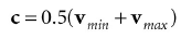
另外AABB也可以通过一个中心点c和一个区域向量e来表示:

DX碰撞库使用center/extents方式来表示:
struct BoundingBox
{
	static const size_t CORNER_COUNT = 8;
	XMFLOAT3 Center; // Center of the box.
	XMFLOAT3 Extents; // Distance from the center to each side.
	…
两种表达方式很容易进行切换,比如如果给出最小点和最大点:
下面的代码展示了如果计算一个骷髅头的包围盒:
XMFLOAT3 vMinf3(+MathHelper::Infinity, +MathHelper::Infinity, +MathHelper::Infinity);
XMFLOAT3 vMaxf3(-MathHelper::Infinity, - MathHelper::Infinity, -MathHelper::Infinity);

XMVECTOR vMin = XMLoadFloat3(&vMinf3);
XMVECTOR vMax = XMLoadFloat3(&vMaxf3);

std::vector<Vertex> vertices(vcount);

for(UINT i = 0; i < vcount; ++i)
{
	fin >> vertices[i].Pos.x >> vertices[i].Pos.y >> vertices[i].Pos.z;
	fin >> vertices[i].Normal.x >> vertices[i].Normal.y >> vertices[i].Normal.z;
	XMVECTOR P = XMLoadFloat3(&vertices[i].Pos);

	// Project point onto unit sphere and generate spherical texture coordinates.
	XMFLOAT3 spherePos;
	XMStoreFloat3(&spherePos, XMVector3Normalize(P));
	float theta = atan2f(spherePos.z, spherePos.x);

	// Put in [0, 2pi].
	if(theta < 0.0f)
		theta += XM_2PI;

	float phi = acosf(spherePos.y);
	float u = theta / (2.0f*XM_PI);
	float v = phi / XM_PI;
	vertices[i].TexC = { u, v };
	vMin = XMVectorMin(vMin, P);
	vMax = XMVectorMax(vMax, P);
}

BoundingBox bounds;
XMStoreFloat3(&bounds.Center, 0.5f*(vMin + vMax));
XMStoreFloat3(&bounds.Extents, 0.5f*(vMax - vMin));
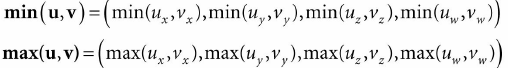
XMVectorMin和XMVectorMax如下:
2.2.1 旋转轴平行的包围盒
如下图所示,如果我们在物体局部坐标系下计算AABB,当放到世界坐标系下时,它可能变成旋转后的包围盒(oriented bounding box(OBB))。当然,我们也可以变换到网格的局部坐标系下进行相交检测。

另外,我们可以在世界坐标系下重新计算AABB,但是这样可能导致包围盒变大,并且不那么近似网格本来的形状:

另外一种方法是放弃AABB,只使用OBB。DirectX碰撞检测库提供了下面的结构来表达OBB:
struct BoundingOrientedBox
{
	static const size_t CORNER_COUNT = 8;

	XMFLOAT3 Center; // Center of the box.
	XMFLOAT3 Extents; // Distance from the center to each side.
	XMFLOAT4 Orientation; // Unit quaternion representing rotation (box -> world).
	…
AABB和OBB可以使用DirectX碰撞检测库中的静态成员函数,通过一组顶点来构建:
void BoundingBox::CreateFromPoints(
	_Out_ BoundingBox& Out,
	_In_ size_t Count,
	_In_reads_bytes_(sizeof(XMFLOAT3)+Stride* (Count-1)) const XMFLOAT3* pPoints,
	_In_ size_t Stride );

void BoundingOrientedBox::CreateFromPoints(
	_Out_ BoundingOrientedBox& Out,
	_In_ size_t Count,
	_In_reads_bytes_(sizeof(XMFLOAT3)+Stride*  (Count-1)) const XMFLOAT3* pPoints,
	_In_ size_t Stride );
如果你的顶点结构如下:
struct Basic32
{
	XMFLOAT3 Pos;
	XMFLOAT3 Normal;
	XMFLOAT2 TexC;
};
然后你有一个顶点数组组成你的网格:
std::vector<Vertex::Basic32> vertices;
那么你可以这样调用这个函数:
BoundingBox box;

BoundingBox::CreateFromPoints(
	box,
	vertices.size(),
	&vertices[0].Pos,
	sizeof(Vertex::Basic32));
stride指定获取下一个元素需要偏移多少。
为了计算你的网格的包围体,你的顶点列表需要系统内存拷贝可用,比如保存到std::vector。这是因为CPU不能通过渲染创建的顶点缓冲来读取数据。所以,对于应用来说,保持系统内存拷贝可用是一致的,例如拾取(下章介绍)。
2.3 球体
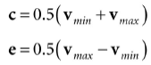
包围球可以通过中心点和半径来表示,第一种计算方法是AABB,中心点计算如下:
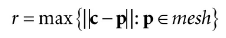
半径通过计算顶点到中心点的最大距离得到:
加入计算包围球是在局部坐标系中进行的,在变换到世界坐标系中时,如果进行了缩放,包围求不一定能紧紧包围网格。第一种策略是根据最大的缩放组件值来缩放半径;另一种方案是变换到世界坐标系中时不进行缩放处理,而是在加载物体网格的时候直接进行缩放操作。
DirectX碰撞检测库提供了下面的结构来表示包围球:
struct BoundingSphere
{
	XMFLOAT3 Center; // Center of the sphere.
	float Radius; // Radius of the sphere.
	…
并且提供了一个静态成员函数来计算它:
void BoundingSphere::CreateFromPoints(
	_Out_ BoundingSphere& Out,
	_In_ size_t Count,
	_In_reads_bytes_(sizeof(XMFLOAT3)+Stride* (Count-1)) const XMFLOAT3* pPoints,
	_In_ size_t Stride );
2.4 截头锥体
截头锥体可以通过6个向内的面来描述:

这六个面的表示可以让我们很容易进行截头锥体和包围体的相交测试。
2.4.1 创建截头锥体平面
其中一个简单的创建方法是在视景坐标系下,截头锥体的中心点在原点,并看向Z轴负方向。
DirectX碰撞检测库提供了下面的结构来表示截头锥体:
struct BoundingFrustum
{
	static const size_t CORNER_COUNT = 8;

	XMFLOAT3 Origin; // Origin of the frustum (and projection).
	XMFLOAT4 Orientation; // Quaternion representing rotation.
	float RightSlope; // Positive X slope (X/Z).
	float LeftSlope; // Negative X slope.
	float TopSlope; // Positive Y slope (Y/Z).
	float BottomSlope; // Negative Y slope.
	float Near, Far; // Z of the near plane and far plane.
	…
在截头锥体的局部坐标系下(比如相机的视景坐标系),Origin是0,Orientation是初始值表示不旋转。我们可以通过这两个值来移动和旋转截头锥体。
如果我们通过缓存截头锥体的高度,宽高比,近平面和远平面来定义摄像机,那么我们就可以使用数学方式定义截头锥体。并且,我们也可能通过透视投影矩阵导出截头锥体平面的方程(在视景坐标系下)(see [Lengyel02] or [Möller08] for two different ways)。XNA碰撞检测库给出了下面的策略,在NDC空间下,截头锥体被歪曲成一个盒子[−1,1] × [−1,1] × [0,1],所以截头锥体的8个顶角就很简单:
// Corners of the projection frustum in homogenous space.
static XMVECTORF32 HomogenousPoints[6] =
{
	{ 1.0f, 0.0f, 1.0f, 1.0f }, // right (at far plane)
	{ -1.0f, 0.0f, 1.0f, 1.0f }, // left
	{ 0.0f, 1.0f, 1.0f, 1.0f }, // top
	{ 0.0f, -1.0f, 1.0f, 1.0f }, // bottom
	{ 0.0f, 0.0f, 0.0f, 1.0f }, // near
	{ 0.0f, 0.0f, 1.0f, 1.0f } // far
};
我们可以计算透视投影的逆矩阵来将这8个顶点变换到视景坐标系下。有了顶点后,截头锥体的平面的计算就变得很简答。下面的DirectX碰撞检测库代码就是通过透视投影矩阵来计算在视景坐标系下的截头锥体:
//----------------------------------------------------------------------------
// Build a frustum from a persepective projection matrix. The matrix may only
// contain a projection; any rotation, translation or scale will cause the
// constructed frustum to be incorrect.
//----------------------------------------------------------------------------
_Use_decl_annotations_ inline void XM_CALLCONV

BoundingFrustum::CreateFromMatrix(
	BoundingFrustum& Out,
	FXMMATRIX Projection )
{
	// Corners of the projection frustum in homogenous space.
	static XMVECTORF32 HomogenousPoints[6] =
	{
		{ 1.0f, 0.0f, 1.0f, 1.0f }, // right (at far plane)
		{ -1.0f, 0.0f, 1.0f, 1.0f }, // left
		{ 0.0f, 1.0f, 1.0f, 1.0f }, // top
		{ 0.0f, -1.0f, 1.0f, 1.0f }, // bottom
		{ 0.0f, 0.0f, 0.0f, 1.0f }, // near
		{ 0.0f, 0.0f, 1.0f, 1.0f } // far
	};

	XMVECTOR Determinant;
	XMMATRIX matInverse = XMMatrixInverse( &Determinant, Projection );

	// Compute the frustum corners in world space.
	XMVECTOR Points[6];
	for( size_t i = 0; i < 6; ++i )
	{
		// Transform point.
		Points[i] = XMVector4Transform( HomogenousPoints[i], matInverse );
	}

	Out.Origin = XMFLOAT3( 0.0f, 0.0f, 0.0f );
	Out.Orientation = XMFLOAT4( 0.0f, 0.0f, 0.0f, 1.0f );

	// Compute the slopes.
	Points[0] = Points[0] * XMVectorReciprocal( XMVectorSplatZ( Points[0] ) );
	Points[1] = Points[1] * XMVectorReciprocal( XMVectorSplatZ( Points[1] ) );
	Points[2] = Points[2] * XMVectorReciprocal( XMVectorSplatZ( Points[2] ) );
	Points[3] = Points[3] * XMVectorReciprocal( XMVectorSplatZ( Points[3] ) );

	Out.RightSlope = XMVectorGetX( Points[0] );
	Out.LeftSlope = XMVectorGetX( Points[1] );
	Out.TopSlope = XMVectorGetY( Points[2] );
	Out.BottomSlope = XMVectorGetY( Points[3] );

	// Compute near and far.
	Points[4] = Points[4] * XMVectorReciprocal( XMVectorSplatW( Points[4] ) );
	Points[5] = Points[5] * XMVectorReciprocal( XMVectorSplatW( Points[5] ) );
	Out.Near = XMVectorGetZ( Points[4] );
	Out.Far = XMVectorGetZ( Points[5] );
}
2.4.2 截头锥体/球体 碰撞检测
因为截头锥体我们使用6个向内的平面来表示,所以检测可以根据下面的状态来:如果存在一个截头锥体平面L,球体在L的负方向,那么我们可以得出结论球体完全在截头锥体以外,如果不存在这样的平面,那么球体就要包含在内。
所以截头锥体的检测修改为和6个平面的检测,如下图所示:令球体有中心点c和半径r。那么从中心点到平面的距离为k = n · c + d

BoundingFrustum类提供了下面的成员函数来测试截头锥体和球体的检测,注意球体和截头锥体必须要在相同的坐标系下:
enum ContainmentType
{
	// The object is completely outside the frustum.
	DISJOINT = 0,
	// The object intersects the frustum boundaries.
	INTERSECTS = 1,
	// The object lies completely inside the frustum volume.
	CONTAINS = 2,
};
ContainmentType BoundingFrustum::Contains( _In_ const BoundingSphere& sphere ) const;
BoundingSphere也包含对于的函数:
ContainmentType BoundingSphere::Contains( _In_ const BoundingFrustum& fr ) const;
2.4.3 截头锥体/AABB 碰撞检测
和与球体的碰撞检测类似,与AABB碰撞检测策略如下:如果存在一个平面L,盒子在L的负半侧,那么盒子就在截头锥体以外,否则就包含/相交在内。
首先找到盒子的一条结果中点,并且最接近平面法向量的对角线向量v,那么判定如下图:

找到与法向量最对齐的对角线向量代码如下:
// For each coordinate axis x, y, z…
for(int j = 0; j < 3; ++j)
{
	// Make PQ point in the same direction as
	// the plane normal on this axis.
	if( planeNormal[j] >= 0.0f )
	{
		P[j] = box.minPt[j];
		Q[j] = box.maxPt[j];
	}
	else
	{
		P[j] = box.maxPt[j];
		Q[j] = box.minPt[j];
	}
}
上面的代码可以从一维的方式查看,选择Pi和Qi然后Qi − Pi和法向量有一个相同的方向:

BoundingFrustum类提供了下面的成员函数来测试AABB和截头锥体,注意他们测试的时候必须在同一个坐标系中:
ContainmentType BoundingFrustum::Contains( _In_ const BoundingBox& box ) const;
BoundingBox也包含类似的函数:
ContainmentType BoundingBox::Contains( _In_ const BoundingFrustum& fr ) const;
3 截头锥体剔除
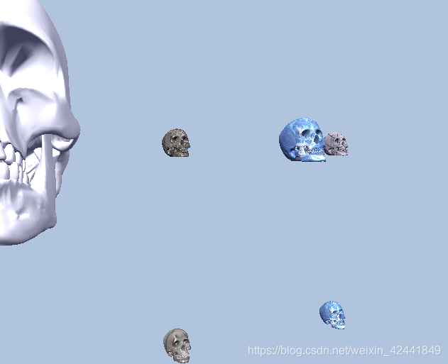
在本Demo中,渲染了5x5x5个骷髅头网格。我们为它们在局部坐标系中创建AABB。在UpdateInstanceData函数中,我们执行截头锥体剔除计算。如果测试通过,我们将它添加到结构化缓冲中,并增加visibleInstanceCount值。那么结构化缓冲中前面的网格就是可见的。因为AABB是在局部坐标系下,所以我们需要变化截头锥体到每个局部坐标系下完成检测;也可以将它们都转换到世界坐标系中,代码如下:
XMMATRIX view = mCamera.GetView();
XMMATRIX invView = XMMatrixInverse(&XMMatrixDeterminant(view), view);
auto currInstanceBuffer = mCurrFrameResource->InstanceBuffer.get();

for(auto& e : mAllRitems)
{
	const auto& instanceData = e->Instances;
	int visibleInstanceCount = 0;

	for(UINT i = 0; i < (UINT)instanceData.size(); ++i)
	{
		XMMATRIX world = XMLoadFloat4x4(&instanceData[i].World);
		XMMATRIX texTransform = XMLoadFloat4x4(&instanceData[i].TexTransform);
		XMMATRIX invWorld = XMMatrixInverse(&XMMatrixDeterminant(world), world);

		// View space to the object’s local space.
		XMMATRIX viewToLocal = XMMatrixMultiply(invView, invWorld);

		// Transform the camera frustum from view space to the object’s local space.
		BoundingFrustum localSpaceFrustum;
		mCamFrustum.Transform(localSpaceFrustum, viewToLocal);

		// Perform the box/frustum intersection test in local space.
		if(localSpaceFrustum.Contains(e->Bounds) != DirectX::DISJOINT)
		{
			InstanceData data;
			XMStoreFloat4x4(&data.World, XMMatrixTranspose(world));
			XMStoreFloat4x4(&data.TexTransform, XMMatrixTranspose(texTransform));
			data.MaterialIndex = instanceData[i].MaterialIndex;

			// Write the instance data to structured buffer for the visible objects.
			currInstanceBuffer->CopyData(visibleInstanceCount++, data);
		}
	}

	e->InstanceCount = visibleInstanceCount;
	// For informational purposes, output the number of instances
	// visible over the total number of instances.
	std::wostringstream outs;
	outs.precision(6);
	outs << L"Instancing and Culling Demo" <<
		L" " << e->InstanceCount <<
		L" objects visible out of " << e-
		>Instances.size();

	mMainWndCaption = outs.str();
}
即使实例化缓冲中可以包含所有实例,但是我们只渲染可见的网格(0到visibleInstanceCount-1):
cmdList->DrawIndexedInstanced(ri->IndexCount,
	ri->InstanceCount,
	ri->StartIndexLocation,
	ri->BaseVertexLocation, 0);
4 总结
- 实例化是指在场景中绘制同一个物体多次,但是使用不同的位置,材质,纹理等。可以绑定SRV到一个结构化缓冲中然后使用SV_InstancedID来索引实例数据。并且可以通过设置ID3D12GraphicsCommandList::DrawIndexedInstanced第二个参数InstanceCount在同一个绘制调用中绘制相关的实例;
- 包围体是近似物体的几何基元。它降低了物体的精度用以更高效和简单的计算(碰撞检测、截头锥体剔除等)。在DirectXCollision.h库中包含AABB和OBB的结构实现;
- GPU自动剔除在视景截头锥体以外的三角形(在裁剪阶段)。但是这些三角形还是会经过渲染管线,通过顶点着色器,也可能通过曲面细分阶段,也可能通过几何着色器阶段。为了提高这个性能,我们手动实现一个截头锥体剔除;主要思路就是使用包围体简化物体,然后进行剔除测试,值提交可见的物体到渲染管线。


 1万+
1万+


 被折叠的 条评论
为什么被折叠?
被折叠的 条评论
为什么被折叠?
 到【灌水乐园】发言


