


代码命名规则
首先说一下代码在命名变量时的规则:“p”表示指针数据类型, "n"表示int类型 ,“b”表示bool类型 "s"表示set类型 ,“v”表示vector数据类型,“I”表示list数据类型 ,“m”表示类的成员变量,“t”表示线程。
其中m、p、v、b我觉得是最常见,知道命名规则的话对代码理解会有一定帮助。
使用的opencv的一些记录
参考的链接是opencv官方文档参考
- KeyPoint关键点
class KeyPoint
	Point2f pt:关键点的点的坐标
	float size:附近响应的直径的大小
	float angle:角度表示关键点的方向
	float response:表示该点角点的程度,显然是差距越多的点的响应值越大
	int octave:表示是从哪一层提取出来的角点
	int class_id:关键点的ID需要自己进行设定
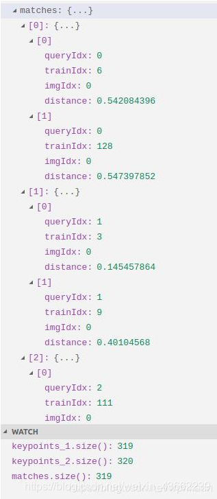
- DMatch 表示的是两个KeyPoint之间的匹配关系
    int queryIdx; //表示match函数前面描述子的索引
    int trainIdx; //表示match函数前面描述子的索引
    int imgIdx;   //匹配图像的下标,比如一幅图像img1的描述子,在其他图像中找到最相似的,imgIdx找到的图像下标
    float distance; //两个描述子之间的距离
- cv::ORB
orb特征和描述子提取器,共有参数如下:
int 	nfeatures = 500, //表示最大提取的特征点数
float 	scaleFactor = 1.2f,	//表示图像金字塔缩放的系数,是一个大于1.0的系数
int 	nlevels = 8, //图像金字塔层数,一般与scaleFactor成反比
int 	firstLevel = 0, //存放原图像的金字塔层数,在该层前面的金字塔层放原图像的放大图像,一般就是0
int 	fastThreshold = 20 //提取的特征点的阈值
int 	edgeThreshold = 31,
int 	WTA_K = 2,
int 	scoreType = ORB::HARRIS_SCORE,
int 	patchSize = 31,

//使用方式演示
cv::Ptr<cv::ORB> orb = cv::ORB::create(100, 1.6, 8, 31, 0, 2, ORB::HARRIS_SCORE, 31, 20);
vector<KeyPoint> keyPoints_res;
cv::Mat descriptors;
//orb表示可以对图像进行检测,从图像中检测出orb特征点
orb->detectAndCompute(rgbd1, Mat(), Keypoints1, descriptors1);
实际上只需要关心三个内容,输入的图像,输出的关键点和关键点对应的描述子
1.InputArray image:待检测的图像
2.InputArray mask
3.std::vector<KeyPoint> &keypoints:需要检测出来的orb特征点
4.OutputArray descriptors:表示每个特征点对应的描述子,可以使用一个Mat也可以使用vector<Mat>
5.bool useProvidedKeypoints
//输入向量InputArray和输出向量OutArray表示的是
typedef const _InputArray& cv::InputArray
typedef const _OutputArray& cv::OutputArray
- 最常规的orb的一个使用步骤
1.将两张图像读进来
Mat img_1 = imread ( argv[1], CV_LOAD_IMAGE_COLOR );
Mat img_2 = imread ( argv[2], CV_LOAD_IMAGE_COLOR );
2.初始化空的角点,空的描述子和初始化好的Orb检测子
std::vector<KeyPoint> keypoints_1, keypoints_2;
Mat descriptors_1, descriptors_2;
cv::Ptr<cv::ORB> orb = cv::ORB::create(100, 1.6, 8, 31, 0, 2, ORB::HARRIS_SCORE, 31, 20);
3.先检测出角点的位置
orb->detect ( img_1,keypoints_1 );
orb->detect ( img_2,keypoints_2 );
4.根据角点的位置计算出对应的描述子
orb->compute ( img_1, keypoints_1, descriptors_1 );
orb->compute ( img_2, keypoints_2, descriptors_2 );
--实际上可以同时把角点位置和描述子同时检测出来
orb->detectAndCompute(rgbd1, Mat(), Keypoints1, descriptors1);
5.初始化匹配点和匹配检测子,匹配的距离结果和角点的位置等没有关系,只跟描述子有关
vector<DMatch> matches;
BFMatcher matcher ( NORM_HAMMING ); //使用汉明距离来进行描述子之间的距离
6.对两个描述子队列进行匹配,比较近的就会匹配到一起,最后给到DMatch
6.1输入两个描述矩阵
6.2输出匹配结果
 matcher->match ( descriptors_1, descriptors_2, matches );
正常的里程计的一个过程
- 里程计的数据中,会包括cur和ref的描述子,之前的3D地图点和当前的角点位置
vector<cv::Point3f>     pts_3d_ref_;        // 3d points in reference frame
vector<cv::KeyPoint>    keypoints_curr_;    // keypoints in current frame
Mat                     descriptors_curr_;  // descriptor in current frame
Mat                     descriptors_ref_;   // descriptor in reference frame
- 代码的过程
1.curr_ = frame;//取到当前对应的图像帧
2.extractKeyPoints();//提取角点的位置
3.computeDescriptors();//提取角点的描述子
4.featureMatching();//根据cur和ref的描述子进行描述子匹配
5.poseEstimationPnP();//利用PNP进行cur和ref之间的相对位姿进行计算
6.checkEstimatedPose();//评估出当前位姿的好坏
7.setRef3DPoints();//设置参考的3D的点
8.checkKeyFrame();//检测是否是关键帧要加入到地图中
- 使用orb检测子来提取角点位置
void VisualOdometry::extractKeyPoints(){
    orb_->detect ( curr_->color_, keypoints_curr_ );
}
- 根据角点的位置进行角点描述子的计算
void VisualOdometry::computeDescriptors(){
    orb_->compute ( curr_->color_, keypoints_curr_, descriptors_curr_ );
}
- 进行角点的匹配,主要是根据描述子的距离进行匹配
void VisualOdometry::featureMatching(){
    vector<cv::DMatch> matches;
    cv::BFMatcher matcher ( cv::NORM_HAMMING );
    matcher.match ( descriptors_ref_, descriptors_curr_, matches );
    =>feature_matches_ //按照距离的远近给出较近的结果给到好的特征匹配
}
- 使用pnp求解当前帧和参考帧的位姿变换关系
- opencv中给出求解pnp的函数接口
cv::solvePnPRansac( pts3d, pts2d, K, Mat(), rvec, tvec, false, 100, 4.0, 0.99, inliers );
1.InputArray objectPoints:表示的是输入的世界坐标系的三维点vector<Point3f>
2.InputArray imagePoints:表示的是从当前的图像中提取出来的角点的位置
3.InputArray cameraMatrix:表示的是相机的内参矩阵
4.InputArray distCoeffs:表示的是当前相机的径向和切向的畸变系数
5.OutputArray rvec:表示的是输出的旋转向量
6.OutputArray tvec:表示的是输出的平移向量
7.bool useExtrinsicGuess = false:如果正确使用提供的旋转和平移向量,然后对这些向量进行优化
8.int iterationsCount = 100:表示的是PNP迭代的次数
9.float reprojectionError = 8.0:表示的是最大投影误差的阈值,小于阈值的表示为内点
10.double 	confidence = 0.99:表示给出正确的pnp结果的置信度
11.OutputArray 	inliers = noArray():表示输出正确的3D点和对应的图像角点
8.int flags = SOLVEPNP_ITERATIVE:表示的是求解pnp的方法
    vector<cv::Point3f> pts3d;
    vector<cv::Point2f> pts2d;
    //距离较近的好的3D点给到求解的3D点
    //当前帧提取的好的点也给到待求解的点
    for ( cv::DMatch m:feature_matches_ )
    {
        pts3d.push_back( pts_3d_ref_[m.queryIdx] );
        pts2d.push_back( keypoints_curr_[m.trainIdx].pt );
    }
    //相机的内参矩阵
    Mat K = ( cv::Mat_<double>(3,3)<<
        ref_->camera_->fx_, 0, ref_->camera_->cx_,
        0, ref_->camera_->fy_, ref_->camera_->cy_,
        0,0,1
    );
    //输出的旋转矩阵,平移向量,对应的3D点和角点
    Mat rvec, tvec, inliers;
    cv::solvePnPRansac( pts3d, pts2d, K, Mat(), rvec, tvec, false, 100, 4.0, 0.99, inliers );
    num_inliers_ = inliers.rows;
    cout<<"pnp inliers: "<<num_inliers_<<endl;
    T_c_r_estimated_ = SE3(
        SO3(rvec.at<double>(0,0), rvec.at<double>(1,0), rvec.at<double>(2,0)),
        Vector3d( tvec.at<double>(0,0), tvec.at<double>(1,0), tvec.at<double>(2,0))
    );
- 评估检测出来位姿变换结果的好坏
num_inliers_ >= min_inliers_ //内点的个数大于最小内点个数的阈值
Sophus::Vector6d d = T_c_r_estimated_.log();
d.norm() <= 5.0 //运动幅度不能太大
- 设置参考的3D的点
void VisualOdometry::setRef3DPoints(){
    // select the features with depth measurements
    pts_3d_ref_.clear(); //清除原有的3D点
    descriptors_ref_ = Mat(); //清空描述子
    for ( size_t i=0; i<keypoints_curr_.size(); i++ )
    {
        double d = ref_->findDepth(keypoints_curr_[i]); //深度有值的化会给出对应点的深度
        if ( d > 0)
        {
            Vector3d p_cam = ref_->camera_->pixel2camera(
                Vector2d(keypoints_curr_[i].pt.x, keypoints_curr_[i].pt.y), d
            ); //图像坐标点加上深度,会给出世界坐标
            pts_3d_ref_.push_back( cv::Point3f( p_cam(0,0), p_cam(1,0), p_cam(2,0) ));
            descriptors_ref_.push_back(descriptors_curr_.row(i));//当前的描述子赋给描述子向量
        }
    }
}
- 检测是否是关键帧要加入到地图中和加入到地图中
bool VisualOdometry::checkKeyFrame()
{
    Sophus::Vector6d d = T_c_r_estimated_.log();
    Vector3d trans = d.head<3>();
    Vector3d rot = d.tail<3>();
    if ( rot.norm() >key_frame_min_rot || trans.norm() >key_frame_min_trans )
        return true; //有足够的运动距离或者旋转足够
    return false;
}

void VisualOdometry::addKeyFrame()
{
    cout<<"adding a key-frame"<<endl;
    map_->insertKeyFrame ( curr_ );
}

void Map::insertKeyFrame ( Frame::Ptr frame )
{
    cout<<"Key frame size = "<<keyframes_.size()<<endl;
    if ( keyframes_.find(frame->id_) == keyframes_.end() )
    {
        keyframes_.insert( make_pair(frame->id_, frame) );
    }//把对应ID的帧给到地图中
    else
    {
        keyframes_[ frame->id_ ] = frame;
    }
}
图优化库g2o的使用记录
- 图优化中节点的BaseVertex的定义
template<int D, typename T> //D表示的优化变量的维度,比如优化相机位姿就是6,T表示优化的数据类型比如SE3Quat
class g2o::BaseVertex< D, T >
1.Matrix< double, D, 1 > _b:优化变量维度为D,总的就是D*1的一个向量
2.BackupStackType _backup:表示优化数据的deque类型
3.EstimateType 	_estimate:表示优化的向量,typedef T EstimateType
4.HessianBlockType	_hessian:表示会把对应的类型映射到Matrix<double,D,D>,
5.Matrix< double, D, D > _uncertainty:表示的是不确定性

0.0:typedef std::stack< EstimateType, std::deque< EstimateType,Eigen::aligned_allocator
< EstimateType >>> BackupStackType
0.1:typedef T 	EstimateType
0.2:typedef Map< Matrix< double, D,D >, Matrix< double, D, D >::Flags &AlignedBit?Aligned:Unaligned > HessianBlockType
0.3:int array[9];
for(int i = 0; i < 9; ++i) array[i] = i;
cout << Map<Matrix3i>(array) << endl; //映射到对应的类型

例子:
- 图优化中边的定义,由于边类型比较多,需要分开进行描述,边的定义一定是要依赖节点的,所以要先定义出节点
template<int D, typename E> //D表示的是节点的维度,E表示的是测量的结果,比如误差Vector2D
class g2o::BaseEdge< D, E >
1.ErrorVector _error:表示的是误差量的维度
2.InformationType  _information:表示的是对方程的约束
3.Measurement _inverseMeasurement:表示的是测量矩阵的逆矩阵,计算error的时候可能会用上
4.Measurement _measurement:表示的是测量矩阵

0.0:typedef Matrix< double, D, 1 > ErrorVector
0.1:typedef Matrix< double, D, D > InformationType
0.2:typedef E Measurement

一、单边
template<int D, typename E, typename VertexXi>
class g2o::BaseUnaryEdge< D, E, VertexXi >
1.JacobianXiOplusType _jacobianOplusXi:表示状态量对误差量求解的雅可比

0.0:typedef Matrix< double, D,VertexXiType::Dimension > JacobianXiOplusType:雅可比,比如重投影误差的话就是 6*2,VertexXiType::Dimension比如位姿就是6,只有旋转就是3
0.1:typedef VertexXi VertexXiType:表示的是边的类型,比如位姿的话就是自己定义的SE3

二、双边
template<int D, typename E, typename VertexXi, typename VertexXj>
class g2o::BaseBinaryEdge< D, E, VertexXi, VertexXj >

1.HessianBlockType _hessian
2.bool _hessianRowMajor
3.HessianBlockTransposedType _hessianTransposed
4.JacobianXiOplusType _jacobianOplusXi
5.JacobianXjOplusType _jacobianOplusXj

0.0:typedef Matrix< double, D, Di > JacobianXiOplusType:表示对Xi的雅可比矩阵,Di是Xi维度
0.1:typedef Matrix< double, D, Dj > JacobianXjOplusType:表示对Yi的雅可比矩阵,Dj是Xj维度
0.2:typedef VertexXi VertexXiType:表示第一个顶点的类型
0.3:typedef VertexXj VertexXjType:表示第二个顶点的类型
0.4:Matrix<double, Di, Dj> HessianBlockType:表示的是两种节点直接的一个Hessian矩阵
0.5:Matrix<double, Dj, Di> HessianBlockTransposedType:表示的是两种节点之间Hessian矩阵的转置矩阵

三、多边暂时不需要看
g2o优化的实例,局部的一个bundle adjustment,摘自orb
对应类型的说明
typedef Sophus::SE3 SE3;
typedef Eigen::Matrix<double, 6, 1> Vec6;
typedef Eigen::Matrix<double, 3, 1> Vec3;
typedef Eigen::Matrix<double, 2, 1> Vec2;
using namespace g2o;
- 对应的节点实际上g2o库中有默认的内容
- 正常的节点有地图点Vector3d 和 相机位姿SE3
2.1地图点就是一个三维的坐标g2o::VertexSBAPointXYZ
  class VertexSBAPointXYZ : public BaseVertex<3, Vector3d>
 {
   public:
     EIGEN_MAKE_ALIGNED_OPERATOR_NEW
     VertexSBAPointXYZ();
     virtual bool read(std::istream& is);
     virtual bool write(std::ostream& os) const;

     virtual void setToOriginImpl() {
       _estimate.fill(0.); //初始值全部设置为0.0
     }

     virtual void oplusImpl(const double* update)
     {
       Eigen::Map<const Vector3d> v(update); //将更新量变成了Vector3d
       _estimate += v; //将更新量加到评估值中更新评估值
     }
 };
附加说明:
Vector3d _estimate;

2.2相机的位姿是用一个李代数来表示g2o::VertexSE3Expmap
 class  VertexSE3Expmap : public BaseVertex<6, SE3Quat>{
 public:
   EIGEN_MAKE_ALIGNED_OPERATOR_NEW

   VertexSE3Expmap();

   bool read(std::istream& is);

   bool write(std::ostream& os) const;

   virtual void setToOriginImpl() {
     _estimate = SE3Quat();
   }

   virtual void oplusImpl(const double* update_)  {
     Eigen::Map<const Vector6d> update(update_);
     setEstimate(SE3Quat::exp(update)*estimate());
   }
 };
 附加说明:
 using namespace Eigen;
 typedef Matrix<double, 6, 6> Matrix6d;
 SE3Quat{
	Quaterniond _r;//使用四元数来表示旋转量
	Vector3d _t;//使用向量来表示位移量}
setEstimate(SE3Quat::exp(update)*estimate());//得到一个更新量后传进来更新李代数 T=exo(eposi)*T
对应的一些边
3.1 表示地图点和相机位姿之间的双元边 g2o::EdgeSE3ProjectXYZ
3.1.0 VertexXi: VertexSBAPointXYZ _vertices[0]
3.1.1 VertexXj: VertexSE3Expmap _vertices[1]
class  EdgeSE3ProjectXYZ: public  BaseBinaryEdge<2, Vector2d, VertexSBAPointXYZ, VertexSE3Expmap>{
 public:
   EIGEN_MAKE_ALIGNED_OPERATOR_NEW
   EdgeSE3ProjectXYZ();
   bool read(std::istream& is);
   bool write(std::ostream& os) const;

   void computeError()  {
     const VertexSE3Expmap* v1 = static_cast<const VertexSE3Expmap*>(_vertices[1]);
     const VertexSBAPointXYZ* v2 = static_cast<const VertexSBAPointXYZ*>(_vertices[0]);//节点坐标的指针
     Vector2d obs(_measurement); //重投影误差表示的就是Vector2d
     _error = obs-cam_project(v1->estimate().map(v2->estimate()));
   }
   //v1->estimate()表示李代数SE3Quat,表示相机的位姿
   //v2->estimate()表示世界坐标系下的坐标Vector3d,通过map变到相机坐标系

   bool isDepthPositive() {
     const VertexSE3Expmap* v1 = static_cast<const VertexSE3Expmap*>(_vertices[1]);
     const VertexSBAPointXYZ* v2 = static_cast<const VertexSBAPointXYZ*>(_vertices[0]);
     return (v1->estimate().map(v2->estimate()))(2)>0.0;//相机坐标系的坐标,z是否大于0
   }
   virtual void linearizeOplus(){
   VertexSE3Expmap * vj = static_cast<VertexSE3Expmap *>(_vertices[1]);
   SE3Quat T(vj->estimate());
   VertexSBAPointXYZ* vi = static_cast<VertexSBAPointXYZ*>(_vertices[0]);

   (1)根据相机的位姿和地图点位置,得到相机坐标系下地图点位置
   Vector3d xyz = vi->estimate(); //世界坐标Pw
   Vector3d xyz_trans = T.map(xyz);//相机坐标系下坐标Pc
   double x = xyz_trans[0];
   double y = xyz_trans[1];
   double z = xyz_trans[2];
   double z_2 = z*z;

   (2)表示对地图点求雅各比矩阵
   Matrix<double,2,3> tmp;
   tmp(0,0) = fx;
   tmp(0,1) = 0;
   tmp(0,2) = -x/z*fx;
   tmp(1,0) = 0;
   tmp(1,1) = fy;
   tmp(1,2) = -y/z*fy;
   _jacobianOplusXi =  -1./z * tmp * T.rotation().toRotationMatrix();

   (3)表示对位姿求雅各比矩阵
   _jacobianOplusXj(0,0) =  x*y/z_2 *fx;
   _jacobianOplusXj(0,1) = -(1+(x*x/z_2)) *fx;
   _jacobianOplusXj(0,2) = y/z *fx;
   _jacobianOplusXj(0,3) = -1./z *fx;
   _jacobianOplusXj(0,4) = 0;
   _jacobianOplusXj(0,5) = x/z_2 *fx;

   _jacobianOplusXj(1,0) = (1+y*y/z_2) *fy;
   _jacobianOplusXj(1,1) = -x*y/z_2 *fy;
   _jacobianOplusXj(1,2) = -x/z *fy;
   _jacobianOplusXj(1,3) = 0;
   _jacobianOplusXj(1,4) = -1./z *fy;
   _jacobianOplusXj(1,5) = y/z_2 *fy;
   }

   Vector2d cam_project(const Vector3d & trans_xyz) const{
	   Vector2d proj = project2d(trans_xyz); //将相机的3维坐标除以深度[x/z,y/z]
	   Vector2d res;
	   res[0] = proj[0]*fx + cx;
	   res[1] = proj[1]*fy + cy;
	   return res; //必须传入相机坐标系的三维点,然后才能转为像素坐标
	}

   double fx, fy, cx, cy;
 };
附加说明:
int _id
VertexContainer _vertices; //typedef std::vector<Vertex*>

3.2 表示位姿之间的优化变量
3.2.0 表示的是位姿的单元边
 class  EdgeSE3ProjectXYZOnlyPose: public  BaseUnaryEdge<2, Vector2d, VertexSE3Expmap>{
 public:
   EIGEN_MAKE_ALIGNED_OPERATOR_NEW

   EdgeSE3ProjectXYZOnlyPose(){}

   bool read(std::istream& is);

   bool write(std::ostream& os) const;

   void computeError()  {
     const VertexSE3Expmap* v1 = static_cast<const VertexSE3Expmap*>(_vertices[0]);
     Vector2d obs(_measurement);
     _error = obs-cam_project(v1->estimate().map(Xw));
   }

   bool isDepthPositive() {
     const VertexSE3Expmap* v1 = static_cast<const VertexSE3Expmap*>(_vertices[0]);
     return (v1->estimate().map(Xw))(2)>0.0;
   }

   virtual void linearizeOplus();

   Vector2d cam_project(const Vector3d & trans_xyz) const;

   Vector3d Xw;
   double fx, fy, cx, cy;
 };
PNP图优化的例子
输入:
1.待优化的三维点:vector<Eigen::Vector3d> &points_3d 世界坐标系3D点
2.待优化的位姿:Sophus::SE3d &pose
3.观测值:vector<Eigen::Vector2d> &points_2d 表示特征角点
4.0 将位姿加入到图中
  g2o::VertexSE3Expmap *vertex_pose = new g2o::VertexSE3Expmap(); // camera vertex_pose
  vertex_pose->setId(0);
  vertex_pose->setEstimate(Sophus::SE3d());
  optimizer.addVertex(vertex_pose);
4.1 将所有的地图点加入图中,只优化位姿,不优化地图点
int index = 1;
for(const Eigen::Vector3d p: points_3d){
  g2o::VertexSBAPointXYZ *point = new g2o::VertexSBAPointXYZ(); // camera vertex_pose
  point->setId(index++);
  point->setEstimate(points_3d);
  optimizer.addVertex(vertex_pose);
}
4.2 将所有的误差加入到图的边中
 int index = 1
 for (size_t i = 0; i < points_2d.size(); ++i) {
    auto p2d = points_2d[i];
    auto p3d = points_3d[i];
    EdgeSE3ProjectXYZ *edge = new EdgeSE3ProjectXYZ();
    edge->setId(index);
    edge->setVertex(0, optimizer.vertex[index]);
    edge->setVertex(0, pose);
    edge->setMeasurement(p2d);
    edge->setInformation(Eigen::Matrix2d::Identity());
    optimizer.addEdge(edge);
    index++;
  }
一般的bundle adjustment
传入结果
1.const vector<KeyFrame *> &vpKFs:表示绑定的关键帧
2.const vector<MapPoint *> &vpMP:表示绑定的地图点
3.1 首先将所有的关键帧的位姿绑定进去
    for(size_t i=0; i<vpKFs.size(); i++)
    {
        KeyFrame* pKF = vpKFs[i];
        if(pKF->isBad())
            continue;
        g2o::VertexSE3Expmap * vSE3 = new g2o::VertexSE3Expmap();
        vSE3->setEstimate(Converter::toSE3Quat(pKF->GetPose()));
        vSE3->setId(pKF->mnId);
        vSE3->setFixed(pKF->mnId==0);//最开始的一帧是不能优化的
        optimizer.addVertex(vSE3);
        if(pKF->mnId>maxKFid)
            maxKFid=pKF->mnId;//计算出所有使用的关键帧的数量
    }


 1399
1399


 被折叠的 条评论
为什么被折叠?
被折叠的 条评论
为什么被折叠?
 到【灌水乐园】发言


