


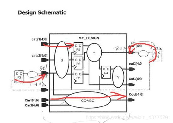
Lab3:实验要进行时序约束的电路框架如下:时序路径用红色箭头标出
该实验主要为一些命令的使用,可能有些枯燥…
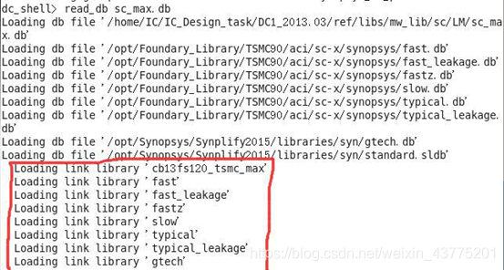
实验的总体步骤如实验 1 那样:设置库搜索路径,打开 dc_shell,确认库,读入设计,读入约束并且编译,生成时序、面积报告。
一些新的指令学习:
read_db sc_max.db #查看逻辑库文件 sc_max.db,可以知道目标库名字(链接库名字为 cb13…)
redirect -file lib.rpt {report_lib cb13fs120_tsmc_max}(report_lib 库名称)生成对于逻辑库的库报告,可以看到库里对应的时间精度为 1ns。(也可以 check_library,查看 sc_max.db 对应的情况)
report_port -verbose 是查看端口的完整约束,比如:
1、port 的 direction、pin load、wire load、max tran、max cap;
2、input delay;
3、driving cell;
4、input port 的 tran;
5、output delay。
Lab3 中没有增加端口的外部约束,lab4 和 lab7 中可以看到该命令的作用。
下面主要是对于时许约束命令的分析:
reset_design #移除存在于上个设计之中的约束条件。
1、create_clock -period 3.0 [get_ports clk]
#生成周期为 3ns(时间单位为 1ns,cheak_library 可以看出),即频率为 333Mhz 的时钟。
BNF:create_clock -period vaule -name clock name [source object] -waveform {egde list} -add -comment “commet for this clock”
-period vaule 为周期;-name clock name 表示时钟名字,缺省时表示时钟名字与源对象名字一致;源对象[source object]可以为端口、引脚、网络,虚拟时钟没有源对象;-waveform {egde list}指明占空比,egde list 中的数值表示一个周期之内第一个时钟上升沿到来的时刻和第一个时钟下降沿到来的时刻,缺省时表示占空比为 50%;-add 表示同源对象的时钟(例如源对象通过多路选择器);-comment “commet for this clock”为注释。
2、set_clock_uncertainty -setup 0.15 [get_clocks clk]
#偏斜 skew:30ps 的信号到达和-30ps 的信号捕获(capture),40ps 的抖动(jitter),50ps 的建立裕度。
用不确定度 uncertainty 将偏斜和抖动模型化。包括内部时钟(相同时钟)和交互时钟(不同但同步时钟)的不确定度:对于内部时钟的不确定度,set_clock_uncertainty value [get_clocks XXX],建立不确定度 set_clock_uncertainty -setup value [get_clocks XXX]受到偏斜和抖动的影响,而保持不确定度只受到 set_clock_uncertainty -hold value [get_clocks XXX]只受到偏斜的影响;对于交互时钟的不确定度,set_clock_uncertainty value -from XX -to XX,其建立不确定度和保持不确定度均受到偏斜和抖动的影响。交互时钟的不确定度优先级更高。
3、set_clock_transition 0.12 [get_clocks clk]
#时钟的过渡时间,set_clock_transition -rise value [get_clocks XX]表示上升过渡时间, set_clock_transition -fall value [get_clocks XX]表示下降过渡时间。
4、set_clock_latency -source -max 0.7 [get_clocks clk] set_clock_latency -max 0.3 [get_clocks clk]
#时钟延迟,包括片外时钟源到定义在端口的时钟的源延迟 set_clock_latency -source -max (-min) value [get_clocks XX],定义在端口的时钟到各个时序单元时钟端口的网络延迟 set_clock_latency -max (-min) value [get_clocks XX],-network 为缺省值。
5、端口输入延时:
set_input_delay -max 0.45 -clock clk [get_ports data*]
input delay+delay of S+clock uncertainty+registor setup time=1 period。
#*表示通配符,端口输入延时+起点(输入端口)和终点(时序原件的输入端)之间的组合逻辑延时+内部捕获时序元件建立不确定度+内部捕获寄存器的建立时间=1 period。通过约束输入延时来使 DC 约束式中其余的延时数据。
set_input_delay -max 0.4 -clock clk [get_ports sel]
last arrival time=source latency+network latency+input delay max
考虑了设计之外的时序元件的输入延时:输入端口延时+源时钟延时+网络时钟延时=最晚达到输入端口的绝对时间。
6、端口输出延时:set_output_delay -max 0.5 -clock clk [get_ports out1]
端口输出延时=起点(时序元件的时钟端)和终点(输出端口)之间的组合逻辑延时+外部捕获寄存器的建立时间。
set_output_delay -max 2.04 -clock clk [get_ports out2]
internal delay+uncertainty+output delay =external capturing clock
输出端口延时+内部延时+内部建立时间不确定度(发送时间不确定度)=外部时序元件捕获时刻。
7、内部组合逻辑的输入、输出端口延时:set_input_delay -max 0.3 -clock clk [get_ports Cin*] set_output_delay -max 0.1 -clock clk [get_ports Cout]
input delay+uncertainty+delay of COMBO+output delay=1 period。
内部组合逻辑的输入端口延时+内部组合逻辑的延时+内部不确定度+内部组合逻辑的输出端口延时=1 period。


 660
660


 被折叠的 条评论
为什么被折叠?
被折叠的 条评论
为什么被折叠?
 到【灌水乐园】发言


