


The MODFLOW River Package simulates surface water/groundwater interaction via a seepage layer separating the surface water body from the groundwater system. VMOD Flex uses the River Package included in MODFLOW. MODFLOW input data for River grid cells is stored in projectname.RIV file.
MODFLOW River Package通过将地表水体与地下水系统分离的渗流层模拟地表水/地下水的相互作用。
VMOD Flex使用MODFLOW中包含的River Package。
河流网格单元的MODFLOW输入数据存储在项目名称中.RIV文件。
Conceptualization in MODFLOW
河流边界条件是地表水特征的简单概念,用于模拟地表水体对地下水流动系统的影响。根据地表水体和地下水系统之间的水力梯度,河流、溪流、湖泊和沼泽等地表水体可以向地下水系统供水,也可以作为地下水排放区。河流(或该边界条件用于表示的其他地表水特征)的概念化表示为河床沉积物的渗流层,假设该渗流层为平底,没有通过河道两侧的渗流,如下所示:

The RIV package approach, fails to take into account the mass balance in the overlying surface water feature and can supply or remove an infinite amount of water to/from the groundwater system. The can produce non-physical results with unexpected amounts of water being exchanged between the groundwater and surface water system both locally and regionally in the model.
The Streamflow-Routing (SFR) package (described below) provides a better representation of river systems, and includes conceptualizations of flow within and between stream reaches, which are entirely ignored in the RIV conceptualization
RIV一揽子方法没有考虑到上覆地表水特征的质量平衡,可以向地下水系统供应或从中排出无限量的水。在模型中,地下水和地表水系统之间的局部和区域交换量出乎意料,这可能会产生非物理结果。
径流路由(SFR)包(如下所述)提供了河流系统的更好表示,并包括河段内和河段之间的流量概念,这些概念在RIV概念化中被完全忽略
Required Data
The MODFLOW River Package input file requires the following information for each grid cell containing a River boundary;
•River Stage: The free water surface elevation of the surface water body. This elevation may change with time.
•Riverbed Bottom: The elevation of the bottom of the seepage layer (bedding material) of the surface water body.
•Conductance: A numerical parameter representing the resistance to flow between the surface water body and the groundwater caused by the seepage layer (riverbed).
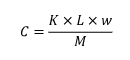
The Conductance value (C) may be calculated from the length of a reach (L) through a cell, the width of the river (W) in the cell, the thickness of the riverbed (M), and the vertical hydraulic conductivity of the riverbed material (K) using the following formula:
 (7)
(7)
For situations where the River package is used to simulate lakes or wetlands, the L and W variables would correspond to the X-Y dimension of the River boundary grid cells. When a River boundary condition is assigned, the Use default Leakance option is automatically selected.
If the Use default Leakance option is selected, the River boundary condition requires the following data:
•River Stage: The free water surface elevation of the surface water body. [L]
•Riverbed Bottom: The elevation of the bottom of the seepage layer (bedding material) of the surface water body. [L]
•Riverbed Thickness: Thickness of the riverbed (seepage layer) [L].
•Leakance: A numerical parameter representing the resistance to flow between the surface water body and the aquifer (this field is read-only and is calculated using the formula described below). [L2/T or L/T, see below]
•Riverbed Kz: Vertical hydraulic conductivity of the riverbed material. [L/T]
•River Width: Width of the river. [L]
When a polyline is used to define the river geometry, the default conductance formula is as follows:
(8)
When a polygon is used to define the river geometry, the default conductance formula is as follows:
(9)
where:
$COND: is the Conductance
$RCHLNG: is the reach length of the river line in each grid cell
$WIDTH: is the River Width in each grid cell
$K: is the Riverbed Kz
$UCTOCOND: is the conversion factor for converting the $K value to the same L and T units used by $COND. $UCTOCOND is automatically calculated by Visual MODFLOW Flex.
$RBTHICK: is the Riverbed Thickness
$DX: is the length of each grid cell in the X-direction
$DY: is the length of each grid cell in the Y-direction
If the "Use default Leakance" option is turned off, the fields used for calculating the River Leakance value (Riverbed Thickness, Riverbed Kz, and River Width) are removed from the table, and the Leakance field becomes a writable field where a value may be entered.
Supported Geometry
The geometry for River boundary conditions can be specified using polylines or polygons
General Head
VMOD Flex supports translation of the General-Head Boundary Package included with MODFLOW. The MODFLOW input data for General-Head grid cells is stored in the projectname.GHB file.
Conceptualization in MODFLOW
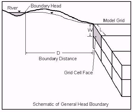
The function of the General-Head Boundary (GHB) Package is mathematically similar to that of the River, Drain, and Evapotranspiration Packages. Flow into or out of a cell from an external source is provided in proportion to the difference between the head in the cell and the reference head assigned to the external source. The application of this boundary condition is intended to be general, as indicated by its name, but the typical application of this boundary condition is to represent heads in a model that are influenced by a large surface water body outside the model domain with a known water elevation. The purpose of using this boundary condition is to avoid unnecessarily extending the model domain outward to meet the element influencing the head in the model. As a result, the General Head boundary condition is usually assigned along the outside edges (sides) of the simulation model domain. This scenario is illustrated in the following figure.
The primary differences between the General-Head boundary and the Specified Head boundary are:
•the model solves for the head values in the General-Head grid cells whereas the head values are specified in Constant Head cells.
•the General-Head grid cells do not act as infinite sources of water whereas Specified Head cells can provide an infinite amount of water as required to maintain the specified head. Therefore, under some circumstances, the General-Head grid cells may become dry cells.
Required Data
The General-Head Boundary Package requires the following information for each General-Head grid cell:
•Stage: This is the head of the external source/sink. This head may be physically based, such as a large lake, or may be obtained through model calibration.
•Conductance: The is a numerical parameter that represents the resistance to flow between the boundary head and the model domain.
In contrast to the River, Drain, and Evapotranspiration packages, the General Head package provides no limiting value of head to bind the linear function in either direction. Therefore, as the head difference between a model cell and the boundary head increases/decreases, flow into or out of the cell continues to increase without limit. Accordingly, care must be used to ensure that unrealistic flows into or out of the system do not develop during the simulation.
The leakance value may be physically based, representing the conductance associated with an aquifer between the model area and a large lake, or may be obtained through model calibration. The leakance value (C) for the scenarios illustrated in the preceding figure may be calculated using the following formula:
(10)
where:
is the surface area of the grid cell face exchanging flow with the external source/sink
is the average hydraulic conductivity of the aquifer material separating the external source/sink from the model grid
is the distance from the external source/sink to the model grid
When a General-Head boundary condition is assigned, the Use default leakance option is automatically selected.
If the "Use default leakance" option is selected, the General-Head boundary condition requires the following data:
•Stage: The head value for the external source/sink
•Leakance: A numerical parameter representing the resistance to flow between the boundary head and the model domain (this field is read-only and is calculated using formula described below)
•Distance to Reservoir: The distance from the external source/sink to the General-Head grid cell
•General Head Average Conductivity: The average hydraulic conductivity of the aquifer material separating the external source/sink from the model grid
The default formula used to calculate the Leakance value for the General-Head boundary is:
(11)
where:
$COND: is the Leakance for each General-Head grid cell
$KAVG: is the Average Conductivity
$FACEAREA: is the surface area of the selected grid cell Face for each General-Head grid cell (automatically calculated during translation)
$UCTOCOND: is the conversion factor for converting the $K value to the same Length (L) and Time (T) units used by $COND. $UCTOCOND is automatically calculated by Visual MODFLOW Flex.
$DIST: is the Boundary Distance, the distance from the external source to the assigned general head boundary
If the "Use default conductance" formula option is not selected, the fields used for calculating the General-Head Conductance value (Distance to Reservoir, Average Conductivity) are removed from the table, and the Leakance field becomes a writable field where a value may be entered.
Supported Geometry
The geometry for General-Head boundary conditions can be specified using a polygon data objects.
Drain
VMOD Flex supports the standard Drain Boundary Package included with MODFLOW. The MODFLOW input data for Drain grid cells is stored in the projectname.DRN file. Currently, for finite element model translation, this boundary condition is not supported.
The Drain Package in MODFLOW is designed to simulate the effects of features such as agricultural drains, which remove water from the aquifer at a rate proportional to the difference between the head in the aquifer and some fixed head or elevation. The Drain package assumes the drain has no effect if the head in the aquifer falls below the fixed head of the drain.
Required Data
The Drain Package requires the following information as input for each cell containing this boundary condition:
•Elevation: The drain elevation, or drain head of the free surface of water within the drain. The drain is assumed to run only partially full, so that the head within the drain is approximately equal to the median elevation of the drain.
•Leakance: The drain leakance is a lumped coefficient describing the head loss between the drain and the groundwater system. This loss is caused by converging flow patterns near the drain, the presence of foreign material around the drain, channel bed materials, the drain wall, and the degree to which the drain pipe openings may be blocked by chemical precipitates, plant roots, etc.
There is no general formulation for calculating drain leakance. In most situations, the detailed information required to calculate drain leakance is not available to the groundwater modeler. These details include the detailed head distribution around the drain, aquifer hydraulic conductivity near the drain, distribution of fill material, number and size of the drain pipe openings, the amount of clogging materials, and the hydraulic conductivity of clogging materials. It is common to calculate drain leakance from measured values of flow rate and head difference. Drain leakance value is usually adjusted during model calibration.
When a polyline is used to define the boundary condition geometry, the default formula for the leakance is as follows:
(11)
When a polygon is used to define the boundary condition geometry, the default leakance formula is as follows:
(12)
where:
$COND: is the Leakance for each drain cell
$RCHLNG: is the reach length of the drain in each grid cell
$LCOND: is the Leakance per unit length of the drain in each grid cell
$SCOND: is the Leakance per unit area of the drain in each grid cell
$DX: is the length of each grid cell in the X-direction
$DY: is the length of each grid cell in the Y-direction
If the Use default leakance option is turned off, the fields used for calculating the Drain Leakance value (Leakance per unit length or area) are removed from the table and the Leakance field becomes a read/write field where any value may be entered.
Supported Geometry
The geometry for General-Head boundary conditions can be specified using polygon or polylines
Streamflow-Routing (SFR2)
Flow in surface water systems is commonly more complex than the simple considerations included in the head-dependent flux boundaries such as RIV, DRN, and GHB packages described above. The streamflow-routing (SFR2) package was developed to include additional/optional complexities associated with surface water features, including:
•mass balance (including optional flow routing) between stream reaches,
•estimation of flow/water depth in stream reaches, and
•unsaturated flow to groundwater system from perched streams
For more information, see the USGS documentation for SFR1 (Prudic et. al., 2004) and SFR2 (Niswonger and Prudic, 2005). The online documentation for SFR2 contains additional information that supplements the USGS documentation, including documentation of the minor differences between the input structures for the versions of MODFLOW (e.g. -2000, -2005, -NWT, -LGR).
![]()
Please note: SFR2 is not currently supported with MODFLOW-USG, MODFLOW-6, MODFLOW-SURFACT, or SEAWAT in Visual MODFLOW Flex.
Conceptualization in MODFLOW
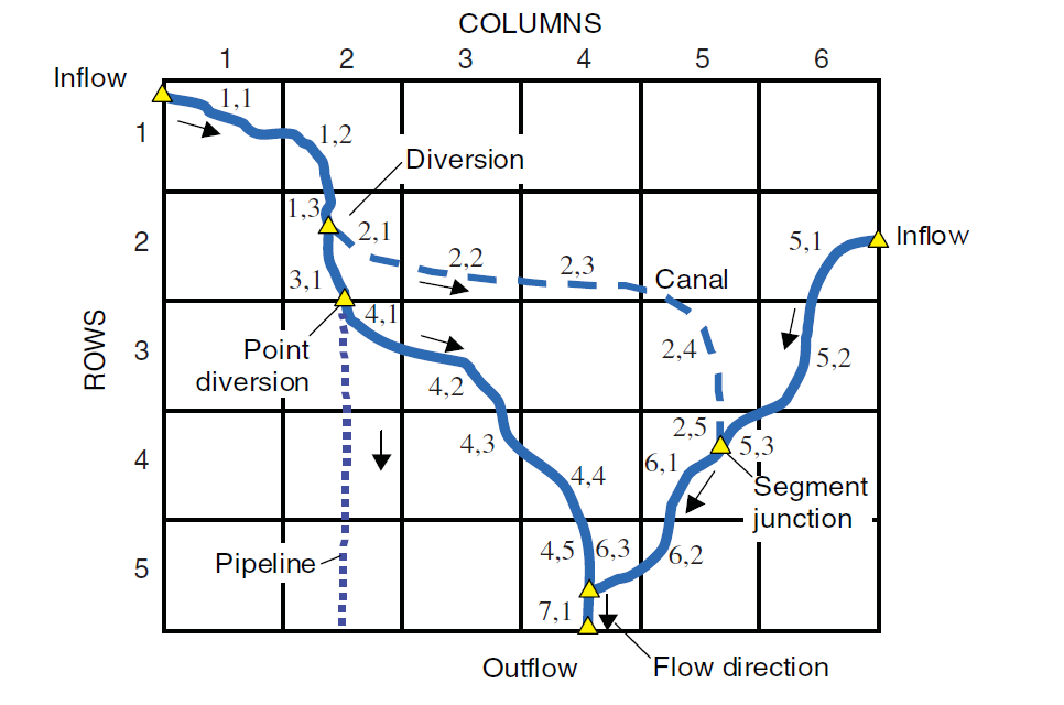
Visual MODFLOW Flex supports surface water drainage systems as one or more networks of directed linear stream segments that may also be connected to polygonal lakes. Each segment or lake is an indexed single part polyline or polygon, respectively. The indices of each stream segment must ascend in the downstream direction and points of confluence (junctions) may either have multiple upstream connections to a single downstream segment (many to one) or one upstream connection to one or more downstream segments (one to many), but not multiple upstream connections to multiple downstream connections (many to many) as this configuration would lead to ambiguous flow routing given the algorithms implemented in SFR2.
|
|
| Example Stream Network: streams are denoted by segment,reach. Where a segment is the polyline in the network and a reach is the portion of a segment within a given cell. Segment and reach indices must increase in the downstream direction. Source: Prudic, et. al. (2004) |
Mass Balance in Streams
Stream flows are estimated in the SFR2 package by a local and global mass balance on stream reaches within the network:
(13)
(14)
where:
is the total inflow to a stream reach [L3/T]
is the total outflow from a stream reach [L3/T]
is a specified inflow to the first reach in a segment [L3/T]. For segments originating within the model domain, this value is zero and non-zero for segments at the model boundary with upstream flows from outside the lateral extents of the model,
is the estimated outflow from each upstream tributary [L3/T],
is the direct runoff from overland flow into the reach [L3/T],
is the direct precipitation into the stream reach [L3/T],
is the groundwater leakage from the stream reach to the hydraulically connected aquifer[L3/T]
is the estimated outflow from the reach [L3/T],
is an optionally specified diversion from the reach [L3/T],
is the direct evapotranspiration from the reach [L3/T],
is the groundwater leakage from a perched stream reach to an underlying aquifer through the vadose zone [L3/T]
In order to estimate groundwater leakage from the stream (whether hydraulically connected or perched), the SFR2 package estimates the depth of the stream at the midpoint of each reach to obtain a head value by adding the estimated depth (dri) at the midpoint of the reach to the estimated bottom elevation of each reach (zri). The bottom elevation at the midpoint is estimated by linearly interpolating the stream bottom elevations specified at the upstream and downstream ends of each segment.
Streamflow Diversions
In general, the stream network in the SFR2 package is assumed to bifurcate in the upstream direction only and the network always converges in the downstream direction towards a single watershed outlet. However, in some cases, flows in the downstream may diverge, either due to natural features (e.g. braided channels, sandbars, etc.) or constructed features (e.g. water intakes, irrigation ditches, canals, etc.). In the former case, where flow always converges, calculating the inflows to the downstream segment is trivial in that they are the sum of the outflows from the upstream segments. However, in the case where flows diverge in the downstream direction, the amount of flow must be divided up to each downstream segment. The SFR2 package provides four options:
•Reduce to available (IPRIOR=0): all available flow at the end of the last reach of a segment up to the rate specified will be diverted from the segment. Thus, if flow in the stream is less than the specified diversion, all available flow in the stream will be diverted, and none will remain in the channel. This option is common to many diversions in the western United States and is the default option for diversions.
•Reduce to None (IPRIOR=1): the specified diversion will only occur if flow in the stream is greater than that of the diversion, if flow is less than the specified diversion, then no flow is diverted and all flow remains in the channel.
•Fraction of Available (IPRIOR=2): a specified fraction of the available flow will be diverted
•Divert Excess (IPRIOR=3): all flow in excess of a specified rate will be diverted. This option is typically used for flood control in which all excess flow is diverted away from the main channel during peak discharge.
Water entering a diversion is subtracted from the end of the last reach of a segment; any remaining flow at the end of the last reach of a segment is added as tributary inflow at the beginning of the first reach in the next downstream segment.
Stream Depth
The depth of the stream in each reach is estimated using one of two supported options in Visual MODFLOW Flex:
•Specified Depth (ICalc=0): the stream depth will be specified at both the upstream and downstream end of the segment and linearly interpolated to the midpoint of each reach
•Variable depth (ICalc=1): the stream depth will be estimated based on the estimated discharge at the midpoint of the stream and Manning's equation, as described below.
The estimated discharge at the midpoint of a reach is based on the assumption that the distributed inflows and outflows are uniform along the length of the channel, that point inflows are located at the upstream end of the reach, and that point outflows occur at the downstream end of the reach and are ignored as follows:
(15)
The depth of the stream at the midpoint is estimated based on a rearranged form of the Manning equation for a "wide" rectangular channel (e.g. the stream is much wider than the depth of the stream and the hydraulic radius is approximately equal to the width of the stream):
(16)
where:
is the estimated stream depth at the midpoint of the reach [L3/T],
is the Manning roughness parameter [-],
is a dimensional constant, which is 1.0 for flow units in m3/s and 1.486 for units of ft3/s [L1/3/T],
is the width of the stream [-],
is the slope of the reach which is estimated by Flex as from the segment length and its upstream and downstream elevations
In the case of variable stream depths calculated by the SFR2 package, the depth of the stream is both an input to the estimate of the groundwater leakance and is indirectly derived from it, which creates a circular dependence that is resolved using Newton-Raphson iterations and a specified tolerance as discussed in Prudic et al (2004).
Stream Leakance (Saturated)
In the case where the stream is directly connected to the groundwater system (i.e. the water table is above the bottom of the stream bed, stream leakance is calculated using the Darcy's law, similar to the implementation in the RIV package:
(17)
where:
is (plan view) area of the streambed in the reach [L2],
is hydraulic conductivity of the bed sediments [L/T],
is the thickness of the bed sediments [L],
is the head in the stream reach [L],
is the head in the groundwater system in the shared model cell [L].
In this case, the exchange between the groundwater system and the stream will be considered to occur instantaneously within the current time step.
Stream Leakance (Unsaturated)
The SFR2 package can also optionally include stream leakance through the unsaturated zone where stream reaches are perched (i.e. in cases where the calculated groundwater head in a cell falls below the bottom of the stream bed). In such reaches, the stream will discharge via the unsaturated zone using the same approach as implemented in the UZF package except:
(18)
where:
is the elevation of the stream bed [L]
Assumptions and Limitations
Major assumptions inherent in the SFR2 approach include the following:
•streamflow is one-dimensional and in the direction of the channel segments
•when the channel depth is specified as variable:
osteady flow in the channel is assumed unless flow routing is active (i.e. TRANSROUTE is specified and IRTFLG=1), in which case the kinematic wave equation is used and dynamic wave effects are ignored
ostream channels are sufficiently wide relative to stream depth such that the hydraulic radius is adequately described by the width of the stream in Manning's equation
oa single value of Manning's roughness coefficient is adequate to estimate stream depths for the range of simulated discharges in each segment (e.g. the stream does not oscillate between flowing within the channel banks and spilling into the floodplain with a significantly different roughness)
ono backwater effects are considered
•flows are routed to downstream reaches based on continuity and the SFR package is not recommended for modeling the surface water flows, depths, or the transient exchange of water between stream reaches and the groundwater system for evaluations of short-term (seconds to days) effects. The inclusion of the kinematic wave routing (i.e. TRANSROUTE option and IRTFLG=1) may provide some improvements as described in Markstrom, et al. (2008).
Other assumptions are also inherent in the implementation of SFR2, a more comprehensive complete list of the assumptions is included in the documentation references discussed above which should be consulted as part of the model development process.
Required Parameters
In Visual MODFLOW Flex, the SFR2 Package requires a more complex set of inputs than the other boundary conditions and as such is defined in its own workflow. Surface Water inputs are grid independent and are based on a set of parameterized vector geometries that define the surface water network consisting of connected/directed stream segments and optional lake polygons. Inputs for each of these is defined in the Surface Water Network Data section.
Supported Geometry
Surface Water inputs are grid-independent and are based on a set of parameterized vector geometries that define the surface water network consisting of connected/directed stream segment polylines and optional lake polygons. A more complete description can be found in the surface water workflow description.
Recharge
Visual MODFLOW Flex supports the Recharge Package (RCH) included with MODFLOW. The Recharge input data for MODFLOW is stored in the projectname.RCH file. For finite element models, recharge boundary conditions are translated as the In(+)/Out(-)flow material parameter.
The recharge boundary condition is typically used to simulate surficially distributed recharge to the groundwater system. Most commonly, recharge occurs as a result of precipitation percolating into the groundwater system. However, the recharge boundary can potentially be used to simulate recharge from sources other than precipitation, such as irrigation, artificial recharge, or seepage from a pond.
![]()
Please Note: The recharge rate is a parameter that is not often directly measured at a site, but rather, it is often assumed to be a percentage of the precipitation. This percentage typically ranges from 5% to 20% of total precipitation depending on many different factors including the predominant land use and vegetation type, the surface topography (slope), and the soil cover material
Required Data
The Recharge Package requires the following information as input for each cell containing this boundary condition:
•Recharge (L/T): The input flux due to recharge. The recharge is applied in one of three ways as part of the package translation settings: 1. recharge is applied only to cells in layer 1, 2. recharge is applied to cells the specified layer, 3. recharge is applied to the upper-most active cell. See the documentation in the Recharge Translation Settings documentation for more details.
•Ponding (L) [optional, only used in the MODFLOW-SURFACT engine]: The maximum allowable depth of the water table above the ground surface. Calculated heads elevations above this depth (+ground surface) are truncated by the model.
![]()
Please Note: MODFLOW-SURFACT simply removes excess ponded water from the model without routing it to other cells.
Supported Geometry
The geometry for Recharge boundary conditions can be specified using polygon data objects and by points, and for an entire layer.


 547
547


 被折叠的 条评论
为什么被折叠?
被折叠的 条评论
为什么被折叠?
 到【灌水乐园】发言


