


Odrive的架构设计很好,把C++非常灵活的应用到了单片机的开发当中,这是用C语言很难做到的一点,因为Odrive能驱动两个电机,面向对象的设计很有必要。
总结了一张系统调用导图,如下:
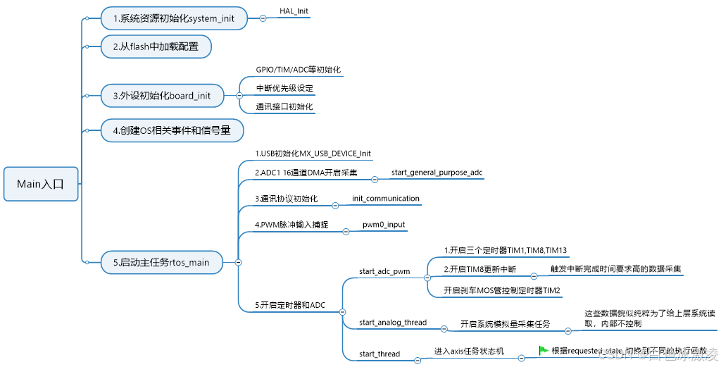
主要的程序脉络在上图中体现了,最终主流程会进入axis的状态机进行循环。
这里需要注意的是,系统把主要的逻辑分为两块:
一是任务部分的逻辑处理,这是在axis状态机里面进行的。
二是实时的闭环控制,这是在TIM8中断函数中进行的。
下面先看axis状态机的逻辑:
一个请求状态可能代表多个顺序执行的任务,通过一个任务数组来实现。
std::array<AxisState, 10> task_chain_ = { AXIS_STATE_UNDEFINED }; switch (current_state_) {
case AXIS_STATE_MOTOR_CALIBRATION: {
// These error checks are a hacky way to force legacy behavior
// when an error is raised. TODO: remove this when we overhaul
// the error architecture
// (https://github.com/madcowswe/ODrive/issues/526).
//if (odrv.any_error())
// goto invalid_state_label;
status = motor_.run_calibration();
} break;
case AXIS_STATE_ENCODER_INDEX_SEARCH: {
//if (odrv.any_error())
// goto invalid_state_label;
if (!motor_.is_calibrated_)
goto invalid_state_label;
status = encoder_.run_index_search();
} break;
case AXIS_STATE_ENCODER_DIR_FIND: {
//if (odrv.any_error())
// goto invalid_state_label;
if (!motor_.is_calibrated_)
goto invalid_state_label;
status = encoder_.run_direction_find();
// Help facilitate encoder.is_ready without reboot
if (status)
encoder_.apply_config(motor_.config_.motor_type);
} break;
case AXIS_STATE_ENCODER_HALL_POLARITY_CALIBRATION: {
if (!motor_.is_calibrated_)
goto invalid_state_label;
status = encoder_.run_hall_polarity_calibration();
} break;
case AXIS_STATE_ENCODER_HALL_PHASE_CALIBRATION: {
if (!motor_.is_calibrated_)
goto invalid_state_label;
if (!encoder_.config_.hall_polarity_calibrated) {
encoder_.set_error(ODriveIntf::EncoderIntf::ERROR_HALL_NOT_CALIBRATED_YET);
goto invalid_state_label;
}
status = encoder_.run_hall_phase_calibration();
} break;
case AXIS_STATE_HOMING: {
Controller::ControlMode stored_control_mode = controller_.config_.control_mode;
Controller::InputMode stored_input_mode = controller_.config_.input_mode;
status = run_homing();
controller_.config_.control_mode = stored_control_mode;
controller_.config_.input_mode = stored_input_mode;
} break;
case AXIS_STATE_ENCODER_OFFSET_CALIBRATION: {
//if (odrv.any_error())
// goto invalid_state_label;
if (!motor_.is_calibrated_)
goto invalid_state_label;
status = encoder_.run_offset_calibration();
} break;
case AXIS_STATE_LOCKIN_SPIN: {
//if (odrv.any_error())
// goto invalid_state_label;
if (!motor_.is_calibrated_ || encoder_.config_.direction==0)
goto invalid_state_label;
status = run_lockin_spin(config_.general_lockin, false);
} break;
case AXIS_STATE_CLOSED_LOOP_CONTROL: {
//if (odrv.any_error())
// goto invalid_state_label;
if (!motor_.is_calibrated_ || (encoder_.config_.direction==0 && !config_.enable_sensorless_mode))
goto invalid_state_label;
watchdog_feed();
status = run_closed_loop_control_loop();
} break;
case AXIS_STATE_IDLE: {
run_idle_loop();
status = true;
} break;
default:
invalid_state_label:
error_ |= ERROR_INVALID_STATE;
status = false; // this will set the state to idle
break;
}每次执行一个任务,执行完进行回滚,最终让数组中的任务全部执行完,代码如下:
        // If the state failed, go to idle, else advance task chain
        if (!status) {
            std::fill(task_chain_.begin(), task_chain_.end(), AXIS_STATE_UNDEFINED);
            current_state_ = AXIS_STATE_IDLE;
        } else {
            std::rotate(task_chain_.begin(), task_chain_.begin() + 1, task_chain_.end());
            task_chain_.back() = AXIS_STATE_UNDEFINED;
        }
再来看实时控制的逻辑
实时控制是在TIM8定时器中断中进行的。函数为:TIM8_UP_TIM13_IRQHandler
void TIM8_UP_TIM13_IRQHandler(void) {
    COUNT_IRQ(TIM8_UP_TIM13_IRQn);

    // Entry into this function happens at 21-23 clock cycles after the timer
    // update event.
    __HAL_TIM_CLEAR_IT(&htim8, TIM_IT_UPDATE);

    // If the corresponding timer is counting up, we just sampled in SVM vector 0, i.e. real current
    // If we are counting down, we just sampled in SVM vector 7, with zero current
    bool counting_down = TIM8->CR1 & TIM_CR1_DIR;

    bool timer_update_missed = (counting_down_ == counting_down);
    if (timer_update_missed) {
        motors[0].disarm_with_error(Motor::ERROR_TIMER_UPDATE_MISSED);
        motors[1].disarm_with_error(Motor::ERROR_TIMER_UPDATE_MISSED);
        return;
    }
    counting_down_ = counting_down;

    timestamp_ += TIM_1_8_PERIOD_CLOCKS * (TIM_1_8_RCR + 1);

    if (!counting_down) {
        TaskTimer::enabled = odrv.task_timers_armed_;
        // Run sampling handlers and kick off control tasks when TIM8 is
        // counting up.
        odrv.sampling_cb();
        NVIC->STIR = ControlLoop_IRQn;
    } else {
        // Tentatively reset all PWM outputs to 50% duty cycles. If the control
        // loop handler finishes in time then these values will be overridden
        // before they go into effect.
        TIM1->CCR1 =
        TIM1->CCR2 =
        TIM1->CCR3 =
        TIM8->CCR1 =
        TIM8->CCR2 =
        TIM8->CCR3 =
            TIM_1_8_PERIOD_CLOCKS / 2;
    }
}
这里每次进行PWM输出打开和关闭MOS管时,都会进行电流采样(打开MOS管时采相压和电源电压,关闭MOS管时采集电流用于标定),最终这些数据都会用于FOC控制。
注意这里的语句:NVIC->STIR = ControlLoop_IRQn;
这里会触发软中断进入ControlLoop_IRQHandler中断函数,大部分的处理都在是这个函数中完成的,在这个函数中会完成ADC的采集,三路PWM输出更新,实时的相电流标定。
void ControlLoop_IRQHandler(void) {
COUNT_IRQ(ControlLoop_IRQn);
uint32_t timestamp = timestamp_;
// Ensure that all the ADCs are done
std::optional<Iph_ABC_t> current0;
std::optional<Iph_ABC_t> current1;
//低侧电流采样,得到相电流
if (!fetch_and_reset_adcs(¤t0, ¤t1)) {
motors[0].disarm_with_error(Motor::ERROR_BAD_TIMING);
motors[1].disarm_with_error(Motor::ERROR_BAD_TIMING);
}
// If the motor FETs are not switching then we can't measure the current
// because for this we need the low side FET to conduct.
// So for now we guess the current to be 0 (this is not correct shortly after
// disarming and when the motor spins fast in idle). Passing an invalid
// current reading would create problems with starting FOC.
if (!(TIM1->BDTR & TIM_BDTR_MOE_Msk)) {
current0 = {0.0f, 0.0f};
}
if (!(TIM8->BDTR & TIM_BDTR_MOE_Msk)) {
current1 = {0.0f, 0.0f};
}
motors[0].current_meas_cb(timestamp - TIM1_INIT_COUNT, current0);
motors[1].current_meas_cb(timestamp, current1);
odrv.control_loop_cb(timestamp);
// By this time the ADCs for both M0 and M1 should have fired again. But
// let's wait for them just to be sure.
MEASURE_TIME(odrv.task_times_.dc_calib_wait) {
while (!(ADC2->SR & ADC_SR_EOC));
}
//电流采样,得到电流用于相电流标定
if (!fetch_and_reset_adcs(¤t0, ¤t1)) {
motors[0].disarm_with_error(Motor::ERROR_BAD_TIMING);
motors[1].disarm_with_error(Motor::ERROR_BAD_TIMING);
}
motors[0].dc_calib_cb(timestamp + TIM_1_8_PERIOD_CLOCKS * (TIM_1_8_RCR + 1) - TIM1_INIT_COUNT, current0);
motors[1].dc_calib_cb(timestamp + TIM_1_8_PERIOD_CLOCKS * (TIM_1_8_RCR + 1), current1);
motors[0].pwm_update_cb(timestamp + 3 * TIM_1_8_PERIOD_CLOCKS * (TIM_1_8_RCR + 1) - TIM1_INIT_COUNT);
motors[1].pwm_update_cb(timestamp + 3 * TIM_1_8_PERIOD_CLOCKS * (TIM_1_8_RCR + 1));
// If we did everything right, the TIM8 update handler should have been
// called exactly once between the start of this function and now.
if (timestamp_ != timestamp + TIM_1_8_PERIOD_CLOCKS * (TIM_1_8_RCR + 1)) {
motors[0].disarm_with_error(Motor::ERROR_CONTROL_DEADLINE_MISSED);
motors[1].disarm_with_error(Motor::ERROR_CONTROL_DEADLINE_MISSED);
}
odrv.task_timers_armed_ = odrv.task_timers_armed_ && !TaskTimer::enabled;
TaskTimer::enabled = false;
}这里存在两次电流采样,作用是不同的。一次是相电流,一次是元器件残留电流。然后控制的逻辑又是在odrv.control_loop_cb(timestamp)函数完成的。


 642
642

 被折叠的 条评论
为什么被折叠?
被折叠的 条评论
为什么被折叠?
 到【灌水乐园】发言


