


4LAN9252
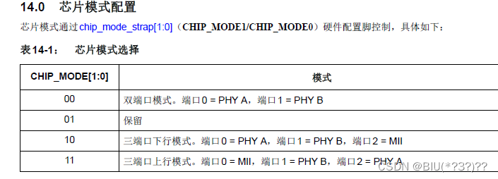
端口配置由硬件引脚决定
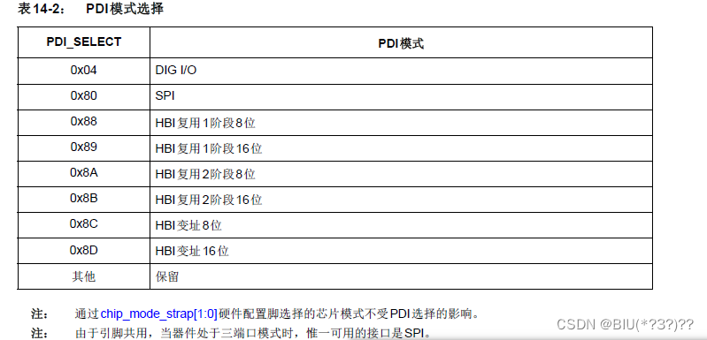
PDI接口模式由寄存器决定
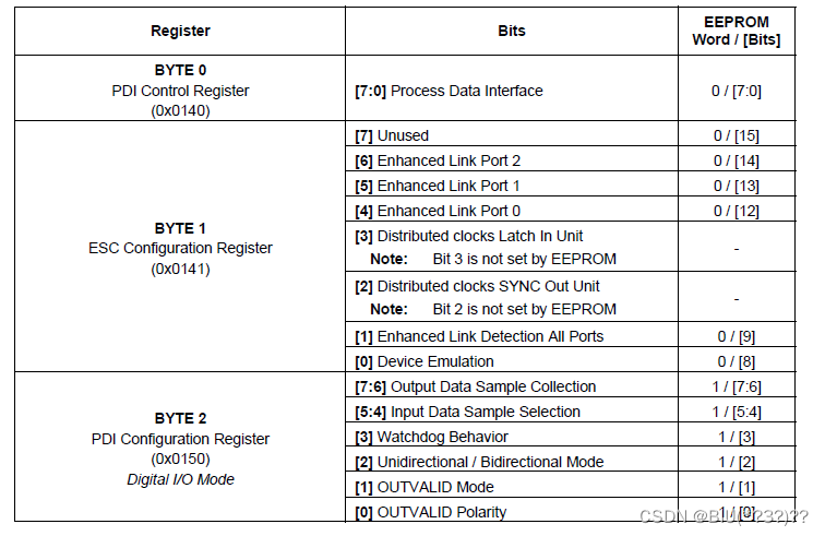
寄存器的配置从EEPROM中读取,EEPROM的配置由XML文件配置
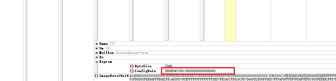
该配置的值由文档《![]() 》可得
》可得
设置为16位变址模式

去MicroChip官网下载 LAN9252-PIC32_SDK_V1.1 文件,里面有与LAN9252的通讯代码,基于该代码文件修改
pmpdrive.c
/*******************************************************************************
PIC32 Host Bus Interface Driver
Company:
Microchip Technology Inc.
File Name:
PMPDriver.c
Summary:
Contains the functional implementation of PIC32 Host Bus Interface Driver
Description:
This file contains the functional implementation of PIC32 Host Bus Interface Driver
Change History:
Version Changes
0.1 Initial version.
1.3 Re-arranged the functions.
*******************************************************************************/
/*******************************************************************************
Copyright (c) 2015 released Microchip Technology Inc. All rights reserved.
Microchip licenses to you the right to use, modify, copy and distribute
Software only when embedded on a Microchip microcontroller or digital signal
controller that is integrated into your product or third party product
(pursuant to the sublicense terms in the accompanying license agreement).
You should refer to the license agreement accompanying this Software for
additional information regarding your rights and obligations.
SOFTWARE AND DOCUMENTATION ARE PROVIDED AS IS WITHOUT WARRANTY OF ANY KIND,
EITHER EXPRESS OR IMPLIED, INCLUDING WITHOUT LIMITATION, ANY WARRANTY OF
MERCHANTABILITY, TITLE, NON-INFRINGEMENT AND FITNESS FOR A PARTICULAR PURPOSE.
IN NO EVENT SHALL MICROCHIP OR ITS LICENSORS BE LIABLE OR OBLIGATED UNDER
CONTRACT, NEGLIGENCE, STRICT LIABILITY, CONTRIBUTION, BREACH OF WARRANTY, OR
OTHER LEGAL EQUITABLE THEORY ANY DIRECT OR INDIRECT DAMAGES OR EXPENSES
INCLUDING BUT NOT LIMITED TO ANY INCIDENTAL, SPECIAL, INDIRECT, PUNITIVE OR
CONSEQUENTIAL DAMAGES, LOST PROFITS OR LOST DATA, COST OF PROCUREMENT OF
SUBSTITUTE GOODS, TECHNOLOGY, SERVICES, OR ANY CLAIMS BY THIRD PARTIES
(INCLUDING BUT NOT LIMITED TO ANY DEFENSE THEREOF), OR OTHER SIMILAR COSTS.
*******************************************************************************/
// *****************************************************************************
// *****************************************************************************
// Section: Included Files
// *****************************************************************************
// *****************************************************************************
#include "stm32f4xx.h"
#include "pmpdriver.h"
#include "string.h"
#define Bank1_SRAM1_ADDR ((uint32_t)0x60000000)
/*******************************************************************************
Function:
void PMPOpen(PMPMode pmpmode, RWType rwtype, Polarity pl)
Summary:
This function configures the PMP(Host Bus Interface) module of SOC.
Description:
This function configures the PMP(Host bus Interface) module of SOC. Refer HBI section of LAN9252 datasheet for more information.
Parameters:
pmpmode- Different modes(INDEXED_8BIT, INDEXED_16BIT, MDP_8BIT, MDP_16BIT, MSP_8BIT, MSP_16BIT)
rwtype - Read and Write on separate pins(MM2) or same pin(MM1)
pl - Different polarities.
*****************************************************************************/
void PMPOpen(void)
{
// FSMC_NORSRAMInitTypeDef FSMC_NORSRAMInitStructure;
// FSMC_NORSRAMTimingInitTypeDef p;
// GPIO_InitTypeDef GPIO_InitStructure;
//
// /* Enable GPIOs clock */
// RCC_AHB1PeriphClockCmd(RCC_AHB1Periph_GPIOD | RCC_AHB1Periph_GPIOE | RCC_AHB1Periph_GPIOF |
// RCC_AHB1Periph_GPIOG, ENABLE);
// /* Enable FSMC clock */
// RCC_AHB3PeriphClockCmd(RCC_AHB3Periph_FSMC, ENABLE);
/*-- GPIOs Configuration -----------------------------------------------------*/
/*
+-------------------+--------------------+------------------+------------------+
| PD0 <-> FSMC_D2 | | PF0 <-> FSMC_A0 | PG0 <-> FSMC_A10 |
| PD1 <-> FSMC_D3 | | PF1 <-> FSMC_A1 | PG1 <-> FSMC_A11 |
| PD4 <-> FSMC_NOE | | PF2 <-> FSMC_A2 | PG2 <-> FSMC_A12 |
| PD5 <-> FSMC_NWE | | PF3 <-> FSMC_A3 | PG3 <-> FSMC_A13 |
| PD8 <-> FSMC_D13 | | PF4 <-> FSMC_A4 | PG4 <-> FSMC_A14 |
| PD9 <-> FSMC_D14 | | PF5 <-> FSMC_A5 | |
| PD10 <-> FSMC_D15 | | PF12 <-> FSMC_A6 | |
| | PE7 <-> FSMC_D4 | PF13 <-> FSMC_A7 |------------------+
| | PE8 <-> FSMC_D5 | PF14 <-> FSMC_A8 |
| | PE9 <-> FSMC_D6 | PF15 <-> FSMC_A9 |
| PD14 <-> FSMC_D0 | PE10 <-> FSMC_D7 |------------------+
| PD15 <-> FSMC_D1 | PE11 <-> FSMC_D8 |
+-------------------| PE12 <-> FSMC_D9 |
PD6-> FSMC_NWAIT | PE13 <-> FSMC_D10 |
PD7 <-> FSMC_NE1 | PE14 <-> FSMC_D11 |
| PE15 <-> FSMC_D12 |
+--------------------+
*/
/* GPIOD configuration */
// GPIO_PinAFConfig(GPIOD, GPIO_PinSource0, GPIO_AF_FSMC);
// GPIO_PinAFConfig(GPIOD, GPIO_PinSource1, GPIO_AF_FSMC);
// GPIO_PinAFConfig(GPIOD, GPIO_PinSource4, GPIO_AF_FSMC);
// GPIO_PinAFConfig(GPIOD, GPIO_PinSource5, GPIO_AF_FSMC);
// GPIO_PinAFConfig(GPIOD, GPIO_PinSource6, GPIO_AF_FSMC);
// GPIO_PinAFConfig(GPIOD, GPIO_PinSource7, GPIO_AF_FSMC);
// GPIO_PinAFConfig(GPIOD, GPIO_PinSource8, GPIO_AF_FSMC);
// GPIO_PinAFConfig(GPIOD, GPIO_PinSource9, GPIO_AF_FSMC);
// GPIO_PinAFConfig(GPIOD, GPIO_PinSource10, GPIO_AF_FSMC);
// GPIO_PinAFConfig(GPIOD, GPIO_PinSource14, GPIO_AF_FSMC);
// GPIO_PinAFConfig(GPIOD, GPIO_PinSource15, GPIO_AF_FSMC);
// GPIO_InitStructure.GPIO_Pin = GPIO_Pin_0 | GPIO_Pin_1 | GPIO_Pin_4 | GPIO_Pin_5 |
// GPIO_Pin_6 | GPIO_Pin_7 | GPIO_Pin_8 | GPIO_Pin_9 |
// GPIO_Pin_10 | GPIO_Pin_14 | GPIO_Pin_15;
//
// GPIO_InitStructure.GPIO_Mode = GPIO_Mode_AF;
// GPIO_InitStructure.GPIO_Speed = GPIO_Speed_100MHz;
// GPIO_InitStructure.GPIO_OType = GPIO_OType_PP;
// GPIO_InitStructure.GPIO_PuPd = GPIO_PuPd_NOPULL;
// GPIO_Init(GPIOD, &GPIO_InitStructure);
// /* GPIOE configuration */
// GPIO_PinAFConfig(GPIOE, GPIO_PinSource7 , GPIO_AF_FSMC);
// GPIO_PinAFConfig(GPIOE, GPIO_PinSource8 , GPIO_AF_FSMC);
// GPIO_PinAFConfig(GPIOE, GPIO_PinSource9 , GPIO_AF_FSMC);
// GPIO_PinAFConfig(GPIOE, GPIO_PinSource10 , GPIO_AF_FSMC);
// GPIO_PinAFConfig(GPIOE, GPIO_PinSource11 , GPIO_AF_FSMC);
// GPIO_PinAFConfig(GPIOE, GPIO_PinSource12 , GPIO_AF_FSMC);
// GPIO_PinAFConfig(GPIOE, GPIO_PinSource13 , GPIO_AF_FSMC);
// GPIO_PinAFConfig(GPIOE, GPIO_PinSource14 , GPIO_AF_FSMC);
// GPIO_PinAFConfig(GPIOE, GPIO_PinSource15 , GPIO_AF_FSMC);
// GPIO_InitStructure.GPIO_Pin = GPIO_Pin_7 |
// GPIO_Pin_8 | GPIO_Pin_9 | GPIO_Pin_10 | GPIO_Pin_11|
// GPIO_Pin_12 | GPIO_Pin_13 | GPIO_Pin_14 | GPIO_Pin_15;
// GPIO_Init(GPIOE, &GPIO_InitStructure);
// /* GPIOF configuration */
// GPIO_PinAFConfig(GPIOF, GPIO_PinSource0 , GPIO_AF_FSMC);
// GPIO_PinAFConfig(GPIOF, GPIO_PinSource1 , GPIO_AF_FSMC);
// GPIO_PinAFConfig(GPIOF, GPIO_PinSource2 , GPIO_AF_FSMC);
// GPIO_PinAFConfig(GPIOF, GPIO_PinSource3 , GPIO_AF_FSMC);
// GPIO_PinAFConfig(GPIOF, GPIO_PinSource4 , GPIO_AF_FSMC);
// GPIO_PinAFConfig(GPIOF, GPIO_PinSource5 , GPIO_AF_FSMC);
// GPIO_PinAFConfig(GPIOF, GPIO_PinSource12 , GPIO_AF_FSMC);
// GPIO_PinAFConfig(GPIOF, GPIO_PinSource13 , GPIO_AF_FSMC);
// GPIO_PinAFConfig(GPIOF, GPIO_PinSource14 , GPIO_AF_FSMC);
// GPIO_PinAFConfig(GPIOF, GPIO_PinSource15 , GPIO_AF_FSMC);
// GPIO_InitStructure.GPIO_Pin = GPIO_Pin_0 | GPIO_Pin_1 | GPIO_Pin_2 | GPIO_Pin_3 |
// GPIO_Pin_4 | GPIO_Pin_5 | GPIO_Pin_12 | GPIO_Pin_13 |
// GPIO_Pin_14 | GPIO_Pin_15;
// GPIO_Init(GPIOF, &GPIO_InitStructure);
// /* GPIOG configuration */
// GPIO_PinAFConfig(GPIOG, GPIO_PinSource0 , GPIO_AF_FSMC);
// GPIO_PinAFConfig(GPIOG, GPIO_PinSource1 , GPIO_AF_FSMC);
// GPIO_PinAFConfig(GPIOG, GPIO_PinSource2 , GPIO_AF_FSMC);
// GPIO_PinAFConfig(GPIOG, GPIO_PinSource3 , GPIO_AF_FSMC);
// GPIO_PinAFConfig(GPIOG, GPIO_PinSource4 , GPIO_AF_FSMC);
// GPIO_InitStructure.GPIO_Pin = GPIO_Pin_0 | GPIO_Pin_1 | GPIO_Pin_2 | GPIO_Pin_3 |
// GPIO_Pin_4 ;
// GPIO_Init(GPIOG, &GPIO_InitStructure);
///*-- FSMC Configuration ------------------------------------------------------*/
// p.FSMC_AddressSetupTime = 2;//
// p.FSMC_AddressHoldTime = 4;//
// p.FSMC_DataSetupTime = 60;
// p.FSMC_BusTurnAroundDuration = 1;
// p.FSMC_CLKDivision = 1;
// p.FSMC_DataLatency = 0;
// p.FSMC_AccessMode = FSMC_AccessMode_A;
// FSMC_NORSRAMInitStructure.FSMC_Bank = FSMC_Bank1_NORSRAM1;
// FSMC_NORSRAMInitStructure.FSMC_DataAddressMux = FSMC_DataAddressMux_Disable;
// FSMC_NORSRAMInitStructure.FSMC_MemoryType = FSMC_MemoryType_SRAM;
// FSMC_NORSRAMInitStructure.FSMC_MemoryDataWidth = FSMC_MemoryDataWidth_16b;
// FSMC_NORSRAMInitStructure.FSMC_BurstAccessMode = FSMC_BurstAccessMode_Disable;
// FSMC_NORSRAMInitStructure.FSMC_AsynchronousWait = FSMC_AsynchronousWait_Disable;
// FSMC_NORSRAMInitStructure.FSMC_WaitSignalPolarity = FSMC_WaitSignalPolarity_Low;
// FSMC_NORSRAMInitStructure.FSMC_WrapMode = FSMC_WrapMode_Disable;
// FSMC_NORSRAMInitStructure.FSMC_WaitSignalActive = FSMC_WaitSignalActive_BeforeWaitState;
// FSMC_NORSRAMInitStructure.FSMC_WriteOperation = FSMC_WriteOperation_Enable;
// FSMC_NORSRAMInitStructure.FSMC_WaitSignal = FSMC_WaitSignal_Disable;
// FSMC_NORSRAMInitStructure.FSMC_ExtendedMode = FSMC_ExtendedMode_Disable;
// FSMC_NORSRAMInitStructure.FSMC_WriteBurst = FSMC_WriteBurst_Disable;
// FSMC_NORSRAMInitStructure.FSMC_ReadWriteTimingStruct = &p;
// FSMC_NORSRAMInitStructure.FSMC_WriteTimingStruct = &p;
// FSMC_NORSRAMInit(&FSMC_NORSRAMInitStructure);
// /*!< Enable FSMC Bank1_SRAM2 Bank */
// FSMC_NORSRAMCmd(FSMC_Bank1_NORSRAM1/*FSMC_Bank1_NORSRAM2*/, ENABLE);
}
/*******************************************************************************
Function:
uint32_t PMPReadDWord (uint16_t Address)
Summary:
This function readS 4 bytes of data from LAN9252 CSR register
Description:
This function readS 4 bytes of data from LAN9252 CSR register( not ESC register).
Refer HBI section of LAN9252 datasheet for more information.
Parameters:
Address - Address of LAN9252 CSR register( not ESC register).
*****************************************************************************/
uint32_t PMPReadDWord (uint16_t Address)
{
UINT32_VAL res;
res.w[0] = *(uint16_t *) (Bank1_SRAM1_ADDR + Address);
res.w[1] = *(uint16_t *) (Bank1_SRAM1_ADDR + Address + 0x02);
return res.Val;
}
/*******************************************************************************
Function:
void PMPWriteDWord (uint16_t Address, uint32_t Val)
Summary:
This function writes 4 bytes of data to the corresponding address of LAN9252 CSR register
Description:
This function writes 4 bytes of data to the corresponding address of LAN9252 CSR register ( not ESC register). Refer HBI section of LAN9252 datasheet for more information.
Parameters:
Address - Address of LAN9252 CSR register( not ESC register).
Val - 4 byte value.
*****************************************************************************/
void PMPWriteDWord (uint16_t Address, uint32_t Val) /****Enter****/
{
UINT32_VAL data;
data.Val=Val;
*(uint16_t *) (Bank1_SRAM1_ADDR + Address) = data.w[0];
*(uint16_t *) (Bank1_SRAM1_ADDR + Address + 0x02) = data.w[1];
}
/*******************************************************************************
Function:
void PMPReadRegUsingCSR(uint8_t *ReadBuffer, uint16_t Address, uint8_t Count)
Summary:
This function reads the EtherCAT core registers using LAN9252 CSR registers.
*****************************************************************************/
void PMPReadRegUsingCSR(uint8_t *ReadBuffer, uint16_t Address, uint8_t Count)
{
UINT32_VAL param32_1 = {0};
uint8_t i = 0;
param32_1.w[0] = Address;
param32_1.v[2] = Count;
param32_1.v[3] = PRAM_RW_BUSY_8B | PRAM_SET_READ;
#ifdef HBI_INDEXED_MODE
PMPWriteDWord (HBI_INDEXED_INDEX0_REG,CSR_CMD_REG);
PMPWriteDWord (HBI_INDEXED_DATA0_REG,param32_1.Val);
#else
PMPWriteDWord (CSR_CMD_REG, param32_1.Val);
#endif
do
{
#ifdef HBI_INDEXED_MODE
param32_1.Val = PMPReadDWord (HBI_INDEXED_DATA0_REG);
#else
param32_1.Val = PMPReadDWord (CSR_CMD_REG);
#endif
}while(param32_1.v[3] & PRAM_RW_BUSY_8B);
#ifdef HBI_INDEXED_MODE
PMPWriteDWord (HBI_INDEXED_INDEX0_REG,CSR_DATA_REG);
param32_1.Val = PMPReadDWord (HBI_INDEXED_DATA0_REG);
#else
param32_1.Val = PMPReadDWord (CSR_DATA_REG);
#endif
for(i=0;i<Count;i++)
ReadBuffer[i] = param32_1.v[i];
return;
}
/*******************************************************************************
Function:
void PMPWriteRegUsingCSR( uint8_t *WriteBuffer, uint16_t Address, uint8_t Count)
Summary:
This function writes the EtherCAT core registers using LAN9252 CSR registers.
*****************************************************************************/
void PMPWriteRegUsingCSR( uint8_t *WriteBuffer, uint16_t Address, uint8_t Count) /****Enter****/
{
UINT32_VAL param32_1 = {0};
uint8_t i = 0;
for(i=0;i<Count;i++)
param32_1.v[i] = WriteBuffer[i];
#ifdef HBI_INDEXED_MODE /****Enter****/
PMPWriteDWord (HBI_INDEXED_INDEX0_REG,CSR_DATA_REG);
PMPWriteDWord (HBI_INDEXED_DATA0_REG,param32_1.Val);
#else
PMPWriteDWord (CSR_DATA_REG, param32_1.Val);
#endif
param32_1.w[0] = Address;
param32_1.v[2] = Count;
param32_1.v[3] = PRAM_RW_BUSY_8B | PRAM_SET_WRITE;
#ifdef HBI_INDEXED_MODE /****Enter****/
PMPWriteDWord (HBI_INDEXED_INDEX0_REG,CSR_CMD_REG);
PMPWriteDWord (HBI_INDEXED_DATA0_REG,param32_1.Val);
#else
PMPWriteDWord (CSR_CMD_REG, param32_1.Val);
#endif
do /****Enter****/
{
#ifdef HBI_INDEXED_MODE /****Enter****/
param32_1.Val = PMPReadDWord (HBI_INDEXED_DATA0_REG);
#else
param32_1.Val = PMPReadDWord (CSR_CMD_REG);
#endif
}while(param32_1.v[3] & PRAM_RW_BUSY_8B);
return;
}
/*******************************************************************************
Function:
void PMPReadPDRamRegister(uint8_t *ReadBuffer, uint16_t Address, uint16_t Count)
Summary:
This function reads the PDRAM using LAN9252 FIFO.
*****************************************************************************/
void PMPReadPDRamRegister(uint8_t *ReadBuffer, uint16_t Address, uint16_t Count)
{
UINT32_VAL param32_1 = {0};
uint8_t i = 0,nlength, nBytePosition;
uint8_t nReadSpaceAvblCount;
// uint16_t RefAddr = Address;
/*Reset/Abort any previous commands.*/
param32_1.Val = PRAM_RW_ABORT_MASK;
/*Set index register 8 for PRAM_READ_CMD_REG.*/
PMPWriteDWord (HBI_INDEXED_INDEX1_REG,PRAM_READ_CMD_REG);
PMPWriteDWord (HBI_INDEXED_DATA1_REG,param32_1.Val);
/*The host should not modify this field unless the PRAM Read Busy
(PRAM_READ_BUSY) bit is a 0.*/
do
{
#ifdef HBI_INDEXED_MODE
param32_1.Val = PMPReadDWord (HBI_INDEXED_DATA1_REG);
#else
param32_1.Val = PMPReadDWord (PRAM_READ_CMD_REG);
#endif
}while((param32_1.v[3] & PRAM_RW_BUSY_8B));
/*Write address and length in the EtherCAT Process RAM Read Address and
* Length Register (ECAT_PRAM_RD_ADDR_LEN)*/
param32_1.w[0] = Address;
param32_1.w[1] = Count;
#ifdef HBI_INDEXED_MODE
/*Set index register 0x10 for PRAM_READ_ADDR_LEN_OFFSET*/
PMPWriteDWord (HBI_INDEXED_INDEX2_REG,PRAM_READ_ADDR_LEN_REG);
PMPWriteDWord (HBI_INDEXED_DATA2_REG,param32_1.Val);
#else
PMPWriteDWord (PRAM_READ_ADDR_LEN_REG, param32_1.Val);
#endif
param32_1.Val = PMPReadDWord (HBI_INDEXED_DATA2_REG );
/*Set PRAM Read Busy (PRAM_READ_BUSY) bit(-EtherCAT Process RAM Read Command Register)
* to start read operatrion*/
param32_1.Val = (uint32_t)PRAM_RW_BUSY_32B; /*TODO:replace with #defines*/
#ifdef HBI_INDEXED_MODE
PMPWriteDWord (HBI_INDEXED_DATA1_REG,param32_1.Val);
#else
PMPWriteDWord (PRAM_READ_CMD_REG, param32_1.Val);
#endif
/*Read PRAM Read Data Available (PRAM_READ_AVAIL) bit is set*/
do
{
#ifdef HBI_INDEXED_MODE
param32_1.Val = PMPReadDWord (HBI_INDEXED_DATA1_REG);
#else
param32_1.Val = PMPReadDWord (PRAM_READ_CMD_REG);
#endif
}while(!(param32_1.v[0] & IS_PRAM_SPACE_AVBL_MASK));
nReadSpaceAvblCount = param32_1.v[1] & PRAM_SPACE_AVBL_COUNT_MASK;
/*Fifo registers are aliased address. In indexed it will read indexed data reg 0x04, but it will point to reg 0
In other modes read 0x04 FIFO register since all registers are aliased*/
#ifdef HBI_INDEXED_MODE
param32_1.Val = PMPReadDWord (HBI_INDEXED_PRAM_READ_WRITE_FIFO);
#else
param32_1.Val = PMPReadDWord (PRAM_READ_FIFO_REG);
#endif
nReadSpaceAvblCount--;
nBytePosition = (Address & 0x03);
nlength = (4-nBytePosition) > Count ? Count:(4-nBytePosition);
memcpy(ReadBuffer+i ,¶m32_1.v[nBytePosition],nlength);
Count-=nlength;
i+=nlength;
while(Count && nReadSpaceAvblCount)
{
#ifdef HBI_INDEXED_MODE
param32_1.Val = PMPReadDWord (HBI_INDEXED_PRAM_READ_WRITE_FIFO);
#else
param32_1.Val = PMPReadDWord (PRAM_READ_FIFO_REG);
#endif
nlength = Count > 4 ? 4: Count;
memcpy((ReadBuffer+i) ,¶m32_1,nlength);
i+=nlength;
Count-=nlength;
nReadSpaceAvblCount --;
if (!nReadSpaceAvblCount)
{
#ifdef HBI_INDEXED_MODE
param32_1.Val = PMPReadDWord (HBI_INDEXED_DATA1_REG);
#else
param32_1.Val = PMPReadDWord (PRAM_READ_CMD_REG);
#endif
nReadSpaceAvblCount = param32_1.v[1] & PRAM_SPACE_AVBL_COUNT_MASK;
}
}
return;
}
/*******************************************************************************
Function:
void PMPWritePDRamRegister(uint8_t *WriteBuffer, uint16_t Address, uint16_t Count)
Summary:
This function writes the PDRAM using LAN9252 FIFO.
*****************************************************************************/
void PMPWritePDRamRegister(uint8_t *WriteBuffer, uint16_t Address, uint16_t Count)
{
UINT32_VAL param32_1 = {0};
uint8_t i = 0,nlength, nBytePosition,nWrtSpcAvlCount;
// uint16_t RefAddr = Address;
/*Reset or Abort any previous commands.*/
param32_1.Val = PRAM_RW_ABORT_MASK; /*TODO:replace with #defines*/
#ifdef HBI_INDEXED_MODE
/*Set index register 0x8 and HBI_INDEXED_DATA1_REG for PRAM_WRITE_CMD_REG*/
PMPWriteDWord (HBI_INDEXED_INDEX1_REG,PRAM_WRITE_CMD_REG);
PMPWriteDWord (HBI_INDEXED_DATA1_REG,param32_1.Val);
#else
PMPWriteDWord (PRAM_WRITE_CMD_REG, param32_1.Val);
#endif
/*Make sure there is no previous write is pending
(PRAM Write Busy) bit is a 0 */
do
{
#ifdef HBI_INDEXED_MODE
param32_1.Val = PMPReadDWord (HBI_INDEXED_DATA1_REG);
#else
param32_1.Val = PMPReadDWord (PRAM_WRITE_CMD_REG);
#endif
}while((param32_1.v[3] & PRAM_RW_BUSY_8B));
/*Write Address and Length Register (ECAT_PRAM_WR_ADDR_LEN) with the
starting byte address and length)*/
param32_1.w[0] = Address;
param32_1.w[1] = Count;
#ifdef HBI_INDEXED_MODE
/*Set index register 0x10 and 0x14 for PRAM_WRITE_ADDR_LEN_REG*/
PMPWriteDWord (HBI_INDEXED_INDEX2_REG,PRAM_WRITE_ADDR_LEN_REG);
PMPWriteDWord (HBI_INDEXED_DATA2_REG,param32_1.Val);
#else
PMPWriteDWord (PRAM_WRITE_ADDR_LEN_REG, param32_1.Val);
#endif
/*write to the EtherCAT Process RAM Write Command Register (ECAT_PRAM_WR_CMD) with the PRAM Write Busy
(PRAM_WRITE_BUSY) bit set*/
param32_1.Val = PRAM_RW_BUSY_32B;
#ifdef HBI_INDEXED_MODE
PMPWriteDWord (HBI_INDEXED_DATA1_REG,param32_1.Val);
#else
PMPWriteDWord (PRAM_WRITE_CMD_REG, param32_1.Val);
#endif
/*Read PRAM write Data Available (PRAM_READ_AVAIL) bit is set*/
do
{
#ifdef HBI_INDEXED_MODE
param32_1.Val = PMPReadDWord (HBI_INDEXED_DATA1_REG);
#else
param32_1.Val = PMPReadDWord (PRAM_WRITE_CMD_REG);
#endif
}while(!(param32_1.v[0] & IS_PRAM_SPACE_AVBL_MASK));
/*Check write data available count*/
nWrtSpcAvlCount = param32_1.v[1] & PRAM_SPACE_AVBL_COUNT_MASK;
/*Write data to Write FIFO) */
/*get the byte lenth for first read*/
nBytePosition = (Address & 0x03);
nlength = (4-nBytePosition) > Count ? Count:(4-nBytePosition);
param32_1.Val = 0;
memcpy(¶m32_1.v[nBytePosition],WriteBuffer+i, nlength);
#ifdef HBI_INDEXED_MODE
PMPWriteDWord (HBI_INDEXED_PRAM_READ_WRITE_FIFO,param32_1.Val);
#else
PMPWriteDWord (PRAM_WRITE_FIFO_REG,param32_1.Val);
#endif
nWrtSpcAvlCount--;
Count-=nlength;
i+=nlength;
while(nWrtSpcAvlCount && Count)
{
nlength = Count > 4 ? 4: Count;
param32_1.Val = 0;
memcpy(¶m32_1, (WriteBuffer+i), nlength);
#ifdef HBI_INDEXED_MODE
PMPWriteDWord (HBI_INDEXED_PRAM_READ_WRITE_FIFO,param32_1.Val);
#else
PMPWriteDWord (PRAM_WRITE_FIFO_REG,param32_1.Val);
#endif
i+=nlength;
Count-=nlength;
nWrtSpcAvlCount--;
if (!nWrtSpcAvlCount)
{
#ifdef HBI_INDEXED_MODE
param32_1.Val = PMPReadDWord (HBI_INDEXED_DATA1_REG);
#else
param32_1.Val = PMPReadDWord (PRAM_WRITE_CMD_REG);
#endif
/*Check write data available count*/
nWrtSpcAvlCount = param32_1.v[1] & PRAM_SPACE_AVBL_COUNT_MASK;
}
}
return;
}
/*******************************************************************************
Function:
void PDIReadReg(uint8_t *ReadBuffer, uint16_t Address, uint16_t Count)
Summary:
This function reads the ESC registers using LAN9252 CSR or FIFO.
*****************************************************************************/
void PMPReadDRegister(uint8_t *ReadBuffer, uint16_t Address, uint16_t Count) /****Enter****/
{
if (Address >= 0x1000)
{
/*Read using FIFO*/
PMPReadPDRamRegister(ReadBuffer, Address,Count);
}
else
{
PMPReadRegUsingCSR(ReadBuffer, Address,Count); /****Enter****/
}
}
/*******************************************************************************
Function:
void PDIWriteReg( uint8_t *WriteBuffer, uint16_t Address, uint16_t Count)
Summary:
This function writes the ESC registers using LAN9252 CSR or FIFO.
*****************************************************************************/
void PMPWriteRegister( uint8_t *WriteBuffer, uint16_t Address, uint16_t Count) /****Enter****/
{
if (Address >= 0x1000)
{
/*Write using FIFO*/
PMPWritePDRamRegister(WriteBuffer, Address,Count);
}
else
{
PMPWriteRegUsingCSR(WriteBuffer, Address,Count);
}
}
/*******************************************************************************
Function:
uint32_t PDIReadLAN9252DirectReg( uint16_t Address)
Summary:
This function reads the LAN9252 CSR registers(Not ESC registers).
*****************************************************************************/
uint32_t PDIReadLAN9252DirectReg( uint16_t Address)
{
uint32_t data;
#ifdef HBI_INDEXED_MODE
PMPWriteDWord (HBI_INDEXED_INDEX0_REG, Address);
data = PMPReadDWord (HBI_INDEXED_DATA0_REG);
#else
data = PMPReadDWord (Address);
#endif
return data;
}
/*******************************************************************************
Function:
void PDIWriteLAN9252DirectReg( uint32_t Val, uint16_t Address)
Summary:
This function writes the LAN9252 CSR registers(Not ESC registers).
*****************************************************************************/
void PDIWriteLAN9252DirectReg( uint32_t Val, uint16_t Address)
{
#ifdef HBI_INDEXED_MODE
/*Set index register 0x8 and HBI_INDEXED_DATA1_REG for PRAM_WRITE_CMD_REG*/
PMPWriteDWord (HBI_INDEXED_INDEX1_REG, Address);
PMPWriteDWord (HBI_INDEXED_DATA1_REG, Val);
#else
PMPWriteDWord (Address, Val);
#endif
}
//下面是个人风格写的,但为了保证移植不改变原有风格,且不出问题,还是使用原有风格
从变址寄存器读取32位数据
//uint32_t PMPReadDWord (uint16_t Address)
//{
// UINT32_VAL res;
//
// res.w[0] = *(uint16_t *) (Bank1_SRAM1_ADDR + Address);
// res.w[1] = *(uint16_t *) (Bank1_SRAM1_ADDR + Address + 0x02);
//
// return res.Val;
//}
从变址寄存器写入32位数据
//void PMPWriteDWord (uint16_t Address, uint32_t Data) /****Enter****/
//{
// UINT32_VAL data;
// data.Val=Data;
// *(uint16_t *) (Bank1_SRAM1_ADDR + Address) = data.w[0];
// *(uint16_t *) (Bank1_SRAM1_ADDR + Address + 0x02) = data.w[1];
//}
通过变址寄存器 读取直接寄存器数据
//uint32_t PDIReadLAN9252DirectReg(uint16_t Address ,uint32_t Index)
//{
// uint32_t TempData ;
//
// //选择使用的变址寄存器
// switch(Index)
// {
// case 0:
// PMPWriteDWord( HBI_ADD_REG0 , Address);
// TempData = PMPReadDWord( HBI_DATA_REG0);
// break;
//
// case 1:
// PMPWriteDWord( HBI_ADD_REG1 , Address);
// TempData = PMPReadDWord( HBI_DATA_REG1);
// break;
//
// case 2:
// PMPWriteDWord( HBI_ADD_REG2 , Address);
// TempData = PMPReadDWord( HBI_DATA_REG2);
// break;
//
// default:
// break;
// }
// return TempData;
//}
通过变址寄存器 写入直接寄存器数据
//void PDIWriteLAN9252DirectReg(uint16_t Address, uint32_t Data ,uint32_t Index)
//{
// //选择使用的变址寄存器
// switch(Index)
// {
// case 0:
// PMPWriteDWord( HBI_ADD_REG0 , Address);
// PMPWriteDWord( HBI_DATA_REG0 , Data);
// break;
//
// case 1:
// PMPWriteDWord( HBI_ADD_REG1 , Address);
// PMPWriteDWord( HBI_DATA_REG1 , Data);
// break;
//
// case 2:
// PMPWriteDWord( HBI_ADD_REG2 , Address);
// PMPWriteDWord( HBI_DATA_REG2 , Data);
// break;
//
// default:
// break;
// }
//}
通过写入CSR直接寄存器,读取EtherCAT寄存器;Count有效值为1,2,4
//void PMPReadRegUsingCSR(uint8_t *ReadBuffer, uint16_t Address, uint8_t Count)
//{
// UINT32_VAL param32_1 = {0};
// UINT8 i = 0,nlength, nBytePosition;
// UINT8 nReadSpaceAvblCount;
// param32_1.w[0] = Address;
// param32_1.v[2] = Count;
// param32_1.v[3] = PRAM_RW_BUSY_8B | PRAM_SET_READ;
// //写入读命令
// PDIWriteLAN9252DirectReg(CSR_CMD_REG,param32_1.Val,0);
// //等待读取命令执行完毕
// do
// {
// param32_1.Val = PDIReadLAN9252DirectReg(CSR_CMD_REG,0);
//
// }while(param32_1.v[3] & PRAM_RW_BUSY_8B);
// //读取数据
// param32_1.Val = PDIReadLAN9252DirectReg(CSR_DATA_REG,0);
//
// for(i=0;i<Count;i++)
// ReadBuffer[i] = param32_1.v[i];
//}
通过写入CSR寄存器,写入EtherCAT寄存器;Count有效值为1,2,4
//void PMPWriteRegUsingCSR( uint8_t *WriteBuffer, uint16_t Address, uint8_t Count) /****Enter****/
//{
// UINT32_VAL param32_1 = {0};
// UINT8 i = 0;
// for(i=0;i<Count;i++)
// param32_1.v[i] = WriteBuffer[i];
// //写入要写的数据
// PDIWriteLAN9252DirectReg(CSR_DATA_REG,param32_1.Val,0);
// param32_1.w[0] = Address;
// param32_1.v[2] = Count;
// param32_1.v[3] = PRAM_RW_BUSY_8B | PRAM_SET_WRITE;
// //写入写命令
// PDIWriteLAN9252DirectReg(CSR_CMD_REG,param32_1.Val,0);
// //等待写操作完成
// do
// {
// param32_1.Val = PDIReadLAN9252DirectReg(CSR_CMD_REG,0);
//
// }while(param32_1.v[3] & PRAM_RW_BUSY_8B);
// return;
//}
只允许以四个字节为单位读写FIFO,即使不需要四个字节也要读四个字节
//void PMPReadPDRamRegister(uint8_t *ReadBuffer, uint16_t Address, uint16_t Count)
//{
// UINT32_VAL param32_1 = {0};
// UINT8 i = 0,nlength, nBytePosition;
// UINT8 nReadSpaceAvblCount;
// //写入 中止读 命令
// param32_1.Val = PRAM_RW_ABORT_MASK;
// PDIWriteLAN9252DirectReg(PRAM_READ_CMD_REG,param32_1.Val,1);
// //等待EtherCAT内核空闲
// do
// {
// param32_1.Val = PDIReadLAN9252DirectReg(PRAM_READ_CMD_REG,1);
// }while((param32_1.v[3] & PRAM_RW_BUSY_8B));
// //写入要读的地址和大小
// param32_1.w[0] = Address;
// param32_1.w[1] = Count;
// PDIWriteLAN9252DirectReg(PRAM_READ_ADDR_LEN_REG,param32_1.Val,2);
// //写入开始读命令
// param32_1.Val = (uint32_t)PRAM_RW_BUSY_32B; /*TODO:replace with #defines*/
// PDIWriteLAN9252DirectReg(PRAM_READ_CMD_REG,param32_1.Val,1);
// //等待有数据可读取
// do
// {
// param32_1.Val = PDIReadLAN9252DirectReg(PRAM_READ_CMD_REG,1);
//
// }while(!(param32_1.v[0] & IS_PRAM_SPACE_AVBL_MASK));
// nReadSpaceAvblCount = param32_1.v[1] & PRAM_SPACE_AVBL_COUNT_MASK; //可读取数据长度(以双字为单位)
// param32_1.Val = PMPReadDWord (HBI_INDEXED_PRAM_READ_WRITE_FIFO); //读取数据
//
// nReadSpaceAvblCount--;
// nBytePosition = (Address & 0x03); //判断首次读的有效字节
// nlength = (4-nBytePosition) > Count ? Count:(4-nBytePosition); //首次读的有效字节长度,不超过count
// memcpy(ReadBuffer+i ,¶m32_1.v[nBytePosition],nlength); //将有效字节写入buffer
// Count-=nlength; //剩余要读的长度
// i+=nlength; //buffer读取位置索引
// while(Count && nReadSpaceAvblCount) //如果读完毕或无可读字节,退出循环
// {
// param32_1.Val = PMPReadDWord (HBI_INDEXED_PRAM_READ_WRITE_FIFO);
// nlength = Count > 4 ? 4: Count; //最大仅允许四个字节读取
// memcpy((ReadBuffer+i) ,¶m32_1,nlength);
// i+=nlength;
// Count-=nlength;
// nReadSpaceAvblCount --;
// if (!nReadSpaceAvblCount) //更新可读字节
// {
// param32_1.Val = PDIReadLAN9252DirectReg(PRAM_READ_CMD_REG,1);
// nReadSpaceAvblCount = param32_1.v[1] & PRAM_SPACE_AVBL_COUNT_MASK;
// }
// }
// return;
//}
//
只允许以四个字节为单位读写FIFO,即使不需要四个字节也要读四个字节
//void PMPWritePDRamRegister(uint8_t *WriteBuffer, uint16_t Address, uint16_t Count)
//{
// UINT32_VAL param32_1 = {0};
// UINT8 i = 0,nlength, nBytePosition,nWrtSpcAvlCount;
// //写入 中止写 操作命令
// param32_1.Val = PRAM_RW_ABORT_MASK; /*TODO:replace with #defines*/
// PDIWriteLAN9252DirectReg(PRAM_WRITE_CMD_REG,param32_1.Val,1);
// //等待EtherCAT内核空闲
// do
// {
// PDIReadLAN9252DirectReg(PRAM_WRITE_CMD_REG,1);
//
// }while((param32_1.v[3] & PRAM_RW_BUSY_8B));
// //写入要操作的地址和大小
// param32_1.w[0] = Address;
// param32_1.w[1] = Count;
// PDIWriteLAN9252DirectReg(PRAM_WRITE_ADDR_LEN_REG,param32_1.Val,2);
// //写入开始写操作
// param32_1.Val = PRAM_RW_BUSY_32B;
// PDIWriteLAN9252DirectReg(PRAM_WRITE_CMD_REG,param32_1.Val,1);
// //等待有可写的操作空间
// do
// {
// param32_1.Val = PDIReadLAN9252DirectReg(PRAM_WRITE_CMD_REG,1);
// }while(!(param32_1.v[0] & IS_PRAM_SPACE_AVBL_MASK));
// nWrtSpcAvlCount = param32_1.v[1] & PRAM_SPACE_AVBL_COUNT_MASK; //可写的数据长度(以双字为单位)
// nBytePosition = (Address & 0x03); //判断首次写的有效字节长度
// nlength = (4-nBytePosition) > Count ? Count:(4-nBytePosition); //首次写的有效字节长度,不超过count
// param32_1.Val = 0;
// memcpy(¶m32_1.v[nBytePosition],WriteBuffer+i, nlength); //将要写的数据写入buffer
// PMPWriteDWord (HBI_INDEXED_PRAM_READ_WRITE_FIFO,param32_1.Val); //写入数据
// nWrtSpcAvlCount--; //可写空间减一
// Count-=nlength; //要写的长度减少
// i+=nlength; //buffer写入位置索引
// while(nWrtSpcAvlCount && Count) //如果写完毕或无可写字节,退出循环
// {
// nlength = Count > 4 ? 4: Count; //单次最大可写4个字节
// param32_1.Val = 0;
// memcpy(¶m32_1, (WriteBuffer+i), nlength);
// PMPWriteDWord (HBI_INDEXED_PRAM_READ_WRITE_FIFO,param32_1.Val);
// i+=nlength;
// Count-=nlength;
// nWrtSpcAvlCount--;
// if (!nWrtSpcAvlCount) //更新可写字节
// {
// param32_1.Val = PDIReadLAN9252DirectReg(PRAM_WRITE_CMD_REG,1);
// nWrtSpcAvlCount = param32_1.v[1] & PRAM_SPACE_AVBL_COUNT_MASK;
// }
// }
// return;
//}
//void PMPReadRegister(uint8_t *ReadBuffer, uint16_t Address, uint16_t Count)
//{
// if (Address >= 0x1000)
// {
// /*Read using FIFO*/
// PMPReadPDRamRegister(ReadBuffer, Address,Count);
// }
// else
// {
// while(Count--)
// {
// PMPReadRegUsingCSR(ReadBuffer, Address, 1);
// ReadBuffer++;
// Address++;
// }
// }
//}
//void PMPWriteRegister( uint8_t *WriteBuffer, uint16_t Address, uint16_t Count)
//{
//
// if (Address >= 0x1000)
// {
// /*Write using FIFO*/
// PMPWritePDRamRegister(WriteBuffer, Address,Count);
// }
// else
// {
// while(Count--)
// {
// PMPWriteRegUsingCSR(WriteBuffer, Address, 1);
// WriteBuffer++;
// Address++;
// }
// }
//
//}
pmpdrive.h文件
/*******************************************************************************
 PIC32 Host Bus Interface Driver

  Company:
    Microchip Technology Inc.

  File Name:
    PMPDriver.h

  Summary:
    Contains the Header File of PIC32 Host Bus Interface Driver

  Description:
    This file contains the Header File of PIC32 Host Bus Interface Driver

  Change History:
    Version		Changes
	0.1			Initial version.
	1.3			Re-arranged the functions.
*******************************************************************************/

/*******************************************************************************
Copyright (c) 2015 released Microchip Technology Inc.  All rights reserved.

Microchip licenses to you the right to use, modify, copy and distribute
Software only when embedded on a Microchip microcontroller or digital signal
controller that is integrated into your product or third party product
(pursuant to the sublicense terms in the accompanying license agreement).

You should refer to the license agreement accompanying this Software for
additional information regarding your rights and obligations.

SOFTWARE AND DOCUMENTATION ARE PROVIDED AS IS WITHOUT WARRANTY OF ANY KIND,
EITHER EXPRESS OR IMPLIED, INCLUDING WITHOUT LIMITATION, ANY WARRANTY OF
MERCHANTABILITY, TITLE, NON-INFRINGEMENT AND FITNESS FOR A PARTICULAR PURPOSE.
IN NO EVENT SHALL MICROCHIP OR ITS LICENSORS BE LIABLE OR OBLIGATED UNDER
CONTRACT, NEGLIGENCE, STRICT LIABILITY, CONTRIBUTION, BREACH OF WARRANTY, OR
OTHER LEGAL EQUITABLE THEORY ANY DIRECT OR INDIRECT DAMAGES OR EXPENSES
INCLUDING BUT NOT LIMITED TO ANY INCIDENTAL, SPECIAL, INDIRECT, PUNITIVE OR
CONSEQUENTIAL DAMAGES, LOST PROFITS OR LOST DATA, COST OF PROCUREMENT OF
SUBSTITUTE GOODS, TECHNOLOGY, SERVICES, OR ANY CLAIMS BY THIRD PARTIES
(INCLUDING BUT NOT LIMITED TO ANY DEFENSE THEREOF), OR OTHER SIMILAR COSTS.
 *******************************************************************************/

// *****************************************************************************
// *****************************************************************************
// Section: Included Files
// *****************************************************************************
// *****************************************************************************

#ifndef PMPDRIVER_H
#define	PMPDRIVER_H

#ifdef	__cplusplus
extern "C" {
#endif

#include "stdint.h"


#define LAN9252_BYTE_ORDER_REG          0x64
#define LAN9252_CSR_INT_CONF            0x54
#define LAN9252_CSR_INT_EN              0x5C
#define LAN9252_CSR_INT_STS             0x58


typedef union
{
	uint32_t Val;
	uint8_t v[4];
	uint16_t w[2];
	struct
	{
		uint8_t LB;
		uint8_t HB;
		uint8_t UB;
		uint8_t MB;
	}byte;
}UINT32_VAL;


typedef union
{
	uint16_t Val;
	struct
	{
		uint8_t LB;
		uint8_t HB;
	}byte;
}UINT16_VAL;


#define	HBI_INDEXED_16BIT  1


#ifdef HBI_INDEXED_8BIT
    #define HBI_MODE INDEXED_8BIT
    #define HBI_INDEXED_MODE
#elif HBI_INDEXED_16BIT
    #define HBI_MODE INDEXED_16BIT
    #define HBI_INDEXED_MODE
#elif HBI_MDP_8BIT
    #define HBI_MODE MDP_8BIT
#elif HBI_MDP_16BIT
    #define HBI_MODE MDP_16BIT
#elif HBI_MSP_8BIT
    #define HBI_MODE MSP_8BIT
#elif HBI_MSP_16BIT
    #define HBI_MODE MSP_16BIT
#else
    #error "Set one of the HBI modes in project setting"
#endif

#define ECAT_REG_BASE_ADDR              0x0300

#define CSR_DATA_REG_OFFSET             0x00
#define CSR_CMD_REG_OFFSET              0x04
#define PRAM_READ_ADDR_LEN_OFFSET       0x08
#define PRAM_READ_CMD_OFFSET            0x0c
#define PRAM_WRITE_ADDR_LEN_OFFSET      0x10
#define PRAM_WRITE_CMD_OFFSET           0x14

#define PRAM_SPACE_AVBL_COUNT_MASK      0x1f
#define IS_PRAM_SPACE_AVBL_MASK         0x01


#define CSR_DATA_REG                    ECAT_REG_BASE_ADDR+CSR_DATA_REG_OFFSET
#define CSR_CMD_REG                     ECAT_REG_BASE_ADDR+CSR_CMD_REG_OFFSET
#define PRAM_READ_ADDR_LEN_REG          ECAT_REG_BASE_ADDR+PRAM_READ_ADDR_LEN_OFFSET
#define PRAM_READ_CMD_REG               ECAT_REG_BASE_ADDR+PRAM_READ_CMD_OFFSET
#define PRAM_WRITE_ADDR_LEN_REG         ECAT_REG_BASE_ADDR+PRAM_WRITE_ADDR_LEN_OFFSET
#define PRAM_WRITE_CMD_REG              ECAT_REG_BASE_ADDR+PRAM_WRITE_CMD_OFFSET

#define PRAM_READ_FIFO_REG              0x04
#define PRAM_WRITE_FIFO_REG             0x20

#define HBI_INDEXED_DATA0_REG           0x04
#define HBI_INDEXED_DATA1_REG           0x0c
#define HBI_INDEXED_DATA2_REG           0x14

#define HBI_INDEXED_INDEX0_REG          0x00
#define HBI_INDEXED_INDEX1_REG          0x08
#define HBI_INDEXED_INDEX2_REG          0x10

#define HBI_INDEXED_PRAM_READ_WRITE_FIFO    0x18

#define PRAM_RW_ABORT_MASK      (1 << 30)
#define PRAM_RW_BUSY_32B        (1 << 31)
#define PRAM_RW_BUSY_8B         (1 << 7)
#define PRAM_SET_READ           (1 << 6)
#define PRAM_SET_WRITE          0


void PMPOpen(void);
void PMPReadDRegister(uint8_t *ReadBuffer, uint16_t Address, uint16_t Count);
void PMPWriteRegister( uint8_t *WriteBuffer, uint16_t Address, uint16_t Count);
void PMPReadPDRamRegister(uint8_t *ReadBuffer, uint16_t Address, uint16_t Count);
void PMPWritePDRamRegister(uint8_t *WriteBuffer, uint16_t Address, uint16_t Count);
uint32_t PDIReadLAN9252DirectReg(uint16_t Address);
void PDIWriteLAN9252DirectReg( uint32_t Val, uint16_t Address);
void PMPWriteDWord (uint16_t Address, uint32_t Val);
uint32_t PMPReadDWord (uint16_t Address);


#ifdef	__cplusplus
}
#endif


#endif	/* PMPDRIVER_H */


//所有寄存器地址
HBI模式配置为16位变址模式
变址模式下,读取/写入直接寄存器需要将地址先写入变址寄存器,再通过数据寄存器读取/写入
///************************ 变址寄存器 Index Read Register ***************/
//#define HBI_ADD_REG0				0x00	//控制直接寄存器的地址寄存器
//#define HBI_DATA_REG0				0x04	//控制直接寄存器的数据寄存器

//#define HBI_ADD_REG1				0x08
//#define HBI_DATA_REG1				0x0C

//#define HBI_ADD_REG2				0x10
//#define HBI_DATA_REG2				0x14

//#define ADD_PROCESS_RAM_FIFO		0x18	//0x18~0x1B 没有理解到怎么用这个FIFO
//#define ADD_HBI_CFG					0x1C
///************************ 变址寄存器 Index Read Register ***************/


///************************ 直接寄存器 Direct Read Register ***************/
系统控制和状态寄存器
//#define ECAT_PRAM_RD_DATA_REG	0x00
//#define ECAT_PRAM_WR_DATA_REG	0x20
//#define ID_REG					0x50
//#define IRQ_CFG_REG				0x54
//#define INT_STS_REG				0x58
//#define INT_EN_REG				0x5C
//#define BYTE_TEST_REG			0x64
//#define HW_CFG_REG				0x74
//#define PMT_CTRL_REG			0x84
//#define GPT_CFG_REG				0x8C
//#define GPT_CNT_REG				0x90
//#define FREE_RUN_REG			0x9C

复位寄存器
//#define RESET_CTL_REG			0x01F8

EtherCAT寄存器
//#define ECAT_CSR_DATA			0x0300		//控制EtherCAT间接寄存器的数据
//#define ECAT_CSR_CMD			0x0304		//控制EtherCAT间接寄存器的指令
//#define ECAT_PRAM_RD_ADDR_LEN	0x0308
//#define ECAT_PRAM_RD_CMD		0x030C
//#define ECAT_PRAM_WR_ADDR_LEN	0x0310
//#define ECAT_PRAM_WR_CMD		0x0314
///************************ 直接寄存器 Direct Read Register ***************/


ECAT CSR间接寄存器需要通过直接寄存器的ECAT_CSR_DATA和ECAT_CSR_CMD进行访问
///********** 间接寄存器 Direct Read Register (ECAT CSR寄存器) ***********/\
ESC信息
//#define TYPE_REG					0x0000
//#define VERSION_REG					0x0001
//#define BUILD_REG					0x0002
//#define FMMU_SUPPORT_REG			0x0004
//#define	SM_SUPPORT_REG				0x0005
//#define RAM_SIZE_REG				0x0006
//#define PORT_REG					0x0007
//#define ESC_FUNCTION_REG			0x0008

站地址
//#define CONFIGUERD_REG				0x0010
//#define CONFIGURED_ALIAS_REG		0x0012

写保护
//#define WR_EN_REG					0x0020
//#define WR_PROTECT_REG				0x0021
//#define	ESC_WR_EN_REG				0x0030
//#define ESC_WR_PROTECT_REG			0x0031

数据链路层
//#define	ESC_RESET_ECAT_REG			0x0040
//#define ESC_RESET_PDI_REG			0x0041
//#define ESC_DL_CTL_REG				0x0100
//#define PHYSICS_RW_OFFSET_REG		0x0108
//#define ESC_DL_STA_REG				0x0110

应用层
//#define AL_CTL_REG					0x0120
//#define AL_STA_REG					0x0130
//#define AL_STA_CODE_REG				0x0134
//#define	RUN_LED_MODFIY_REG			0x0138

PDI(过程数据接口)
//#define PDI_CTL_REG					0x0140
//#define ESC_CFG_REG					0x0141
//#define	ASIC_CFG_REG				0x0142
//#define	PDI_CFG_REG					0x0150
//#define SYNC_PDI_CFG_REG			0x0151
//#define	EXTEND_CFG_REG				0x0152

中断
//#define	ECAT_EVENT_MASK_REG			0x0200
//#define AL_EVENT_MASK_REG			0x0204
//#define ECAT_EVENT_REQUEST_REG		0x0210
//#define AL_EVENT_REQUEST_REG		0x0220

错误计数器
//#define ERROR_RECV_CNT_REG			0x0300
//#define TRAN_ERROR_RECV_CNT_REG		0x0308
//#define ECAT_ERROR_CNT_REG			0x030C
//#define PDI_ERROR_CNT_REG			0x030D
//#define PDI_ERROR_CODE_REG			0x030E
//#define LOSE_LINK_CNT_REG			0x0310

看门狗
//#define WDT_PSC_REG					0x0400
//#define WDT_TIMER_PDI_REG			0x0410
//#define WDT_TIMER_PDO_REG			0x0420
//#define WDT_STA_PDO_REG				0x0440
//#define WDT_CNT_PDO_REG				0x0442
//#define WDT_CNT_PDI_REG				0x0443

EEPROM接口
//#define EEPROM_CFG_REG				0x0500
//#define EEPROM_PDI_RD_STA_REG		0x0501
//#define EEPROM_CTL_STA_REG			0x0502
//#define EEPROM_ADD_REG				0x0504
//#define EEPROM_DATA_REG				0x0508

MII管理接口
//#define MII_MANGE_CTL_STA_REG		0x0510
//#define PHY_ADD_REG					0x0512
//#define PHY_REG_ADD_REG				0x0513
//#define PHY_DATA_REG				0x0514
//#define MII_MANGE_ECAT_RD_STA_REG	0x0516
//#define MII_MANGE_PDI_RD_STA_REG	0x0517
//#define PHY_PORT_STA_REG			0x0518
//#define FMMU_LOGIC_START_ADD_REG	0x0600
//#define FMMU_LENGTH_REG				0x0604
//#define FMMU_LOGIC_START_BIT_REG	0x0606
//#define FMMU_LOGIC_STOP_BIT_REG		0x0607
//#define FMMU_PHYSICS_START_ADD_REG	0x0608
//#define FMMU_PHYSICS_START_BIT_REG	0x060A
//#define FMMU_TYPE_REG				0x060B
//#define FMMU_ACTIVE_REG				0x060C
//#define FMMU_REVERSE_REG			0x060D
//#define SM_PHYSICS_START_ADD_REG	0x0800
//#define SM_LENGTH_REG				0x0802
//#define SM_CTL_REG					0x0804
//#define SM_STA_REG					0x0805
//#define SM_ACT_REG					0x0806
//#define SM_PDI_CTL_REG				0x0807

分布式时钟--接收时间
//#define RECV_TIME_PORT0_REG			0x0900
//#define RECV_TIME_PORT1_REG			0x0904
//#define RECV_TIME_PORT2_REG			0x0908

分布式时钟--时间环路控制单元
//#define SYS_TIME_REG				0x0910
//#define RECV_REG_ECAT_REG			0x0918
//#define SYS_TIME_OFFSET_REG			0x0920
//#define SYS_TIME_DELAY_REG			0x0928
//#define SYS_TIME_DIFF_VALUE_REG		0x092C
//#define SPEED_COUNT_START_VALUE_REG	0x0930
//#define SPEED_COUNT_DIFF_VALUE_REG	0x0932
//#define SYS_TIME_FILTER_DEEP_REG	0x0934
//#define SPEED_COUNT_FILTER_DEEP_REG	0x0935

分布式时钟--循环单元控制
//#define CIRCLE_CTL_REG				0x0980

分布式时钟--SYNC输出单元
//#define ACTIVE_REG					0x0981
//#define SYNC_SIGN_REG_PILSE_LENGTH	0x0982
//#define ACTIVE_STA_REG				0x0984
//#define SYNC0_STA_REG				0x098E
//#define SYNC1_STA_REG				0x098F
//#define START_TIME_CIRCLE_OP_REG	0x0990
//#define NEXT_SYNC1_PULSE_REG		0x0998
//#define SYNC0_PERIOD_TIME_REG		0x09A0
//#define SYNC1_PERIOD_TIME_REG		0x09A4

分布式时钟--锁存输入单元
//#define LATCH0_CTL_REG				0x09A8
//#define LATCH1_CTL_REG				0x09A9
//#define LATCH0_STA_REG				0x09AE
//#define LATCH1_STA_REG				0x09AF
//#define LATCH0_TIME_RISE_EDGE_REG	0x09B0
//#define LATCH0_TIME_DOWN_EDGE_REG	0x09B8
//#define LATCH1_TIME_RISE_EDGE_REG	0x09C0
//#define LATCH1_TIME_DOWN_EDGE_REG	0x09C8

分布式时钟--SM事件时间
//#define ECAT_BUF_CHAN_EVT_TIME_REG	0x09F0
//#define PDI_BUF_START_TIME_EVT_REG	0x09F8
//#define PDI_BUF_CHAN_EVT_TIME_REG	0x09FC

ESC特定
//#define PRODUCT_ID_REG				0x0E00
//#define SUPPLIER_ID_REG				0x0E08

数字输入/输出
//#define IO_OUTPUT_DATA_REG			0x0F00
//#define GPOUT_REG					0x0F10
//#define GPIN_REG					0x0F18

用户RAM
//#define USER_RAM_REG				0x0F80

过程数据RAM
//#define IO_INPUT_DATA_REG			0x1000
//#define PDO_RAM_REG					0x1000	//0x1000-0x1FFF
///********** 间接寄存器 Direct Read Register (ECAT CSR寄存器) ***********/
el9800hw.c
LAN9252是需要配置寄存器产生中断的
/*
* This source file is part of the EtherCAT Slave Stack Code licensed by Beckhoff Automation GmbH & Co KG, 33415 Verl, Germany.
* The corresponding license agreement applies. This hint shall not be removed.
*/

/**
\addtogroup EL9800_HW EL9800 Platform (Serial ESC Access)
@{
*/

/**
\file    el9800hw.c
\author EthercatSSC@beckhoff.com
\brief Implementation
Hardware access implementation for EL9800 onboard PIC18/PIC24 connected via SPI to ESC

\version 5.12

<br>Changes to version V5.11:<br>
V5.12 EL9800 1: improve the SPI access<br>
<br>Changes to version V5.10:<br>
V5.11 ECAT10: change PROTO handling to prevent compiler errors<br>
V5.11 EL9800 2: change PDI access test to 32Bit ESC access and reset AL Event mask after test even if AL Event is not enabled<br>
<br>Changes to version V5.01:<br>
V5.10 ESC5: Add missing swapping<br>
V5.10 HW3: Sync1 Isr added<br>
V5.10 HW4: Add volatile directive for direct ESC DWORD/WORD/BYTE access<br>
           Add missing swapping in mcihw.c<br>
           Add "volatile" directive vor dummy variables in enable and disable SyncManger functions<br>
           Add missing swapping in EL9800hw files<br>
<br>Changes to version V5.0:<br>
V5.01 HW1: Invalid ESC access function was used<br>
<br>Changes to version V4.40:<br>
V5.0 ESC4: Save SM disable/Enable. Operation may be pending due to frame handling.<br>
<br>Changes to version V4.30:<br>
V4.40 : File renamed from spihw.c to el9800hw.c<br>
<br>Changes to version V4.20:<br>
V4.30 ESM: if mailbox Syncmanger is disabled and bMbxRunning is true the SyncManger settings need to be revalidate<br>
V4.30 EL9800: EL9800_x hardware initialization is moved to el9800.c<br>
V4.30 SYNC: change synchronisation control function. Add usage of 0x1C32:12 [SM missed counter].<br>
Calculate bus cycle time (0x1C32:02 ; 0x1C33:02) CalcSMCycleTime()<br>
V4.30 PDO: rename PDO specific functions (COE_xxMapping -> PDO_xxMapping and COE_Application -> ECAT_Application)<br>
V4.30 ESC: change requested address in GetInterruptRegister() to prevent acknowledge events.<br>
(e.g. reading an SM config register acknowledge SM change event)<br>
GENERIC: renamed several variables to identify used SPI if multiple interfaces are available<br>
V4.20 MBX 1: Add Mailbox queue support<br>
V4.20 SPI 1: include SPI RxBuffer dummy read<br>
V4.20 DC 1: Add Sync0 Handling<br>
V4.20 PIC24: Add EL9800_4 (PIC24) required source code<br>
V4.08 ECAT 3: The AlStatusCode is changed as parameter of the function AL_ControlInd<br>
<br>Changes to version V4.02:<br>
V4.03 SPI 1: In ISR_GetInterruptRegister the NOP-command should be used.<br>
<br>Changes to version V4.01:<br>
V4.02 SPI 1: In HW_OutputMapping the variable u16OldTimer shall not be set,<br>
             otherwise the watchdog might exceed too early.<br>
<br>Changes to version V4.00:<br>
V4.01 SPI 1: DI and DO were changed (DI is now an input for the uC, DO is now an output for the uC)<br>
V4.01 SPI 2: The SPI has to operate with Late-Sample = FALSE on the Eva-Board<br>
<br>Changes to version V3.20:<br>
V4.00 ECAT 1: The handling of the Sync Manager Parameter was included according to<br>
              the EtherCAT Guidelines and Protocol Enhancements Specification<br>
V4.00 APPL 1: The watchdog checking should be done by a microcontroller<br>
                 timer because the watchdog trigger of the ESC will be reset too<br>
                 if only a part of the sync manager data is written<br>
V4.00 APPL 4: The EEPROM access through the ESC is added

*/


/*--------------------------------------------------------------------------------------
------
------    Includes
------
--------------------------------------------------------------------------------------*/
#include "ecat_def.h"

#include "ecatslv.h"


#define    _EL9800HW_ 1
#include "el9800hw.h"
#undef    _EL9800HW_
/*remove definition of _EL9800HW_ (#ifdef is used in el9800hw.h)*/

#include "ecatappl.h"

#include "stm32f4xx.h"
#include "pmpdriver.h"
#include "tim.h"

/*--------------------------------------------------------------------------------------
------
------    internal Types and Defines
------
--------------------------------------------------------------------------------------*/

typedef union
{
    unsigned short    Word;
    unsigned char    Byte[2];
} UBYTETOWORD;

typedef union
{
    UINT8           Byte[2];
    UINT16          Word;
}
UALEVENT;

/*-----------------------------------------------------------------------------------------
------
------    SPI defines/macros
------
-----------------------------------------------------------------------------------------*/

/*-----------------------------------------------------------------------------------------
------
------    Global Interrupt setting
------
-----------------------------------------------------------------------------------------*/

/*-----------------------------------------------------------------------------------------
------
------    ESC Interrupt
------
-----------------------------------------------------------------------------------------*/


/*-----------------------------------------------------------------------------------------
------
------    SYNC0 Interrupt
------
-----------------------------------------------------------------------------------------*/
#define     ENABLE_SYNC0_INT	NVIC_EnableIRQ(EXTI1_IRQn)
#define     ENABLE_SYNC1_INT	NVIC_EnableIRQ(EXTI2_IRQn)

#define 	START_ECAT_TIMER	{NVIC_EnableIRQ(TIM2_IRQn);}

/*-----------------------------------------------------------------------------------------
------
------    Hardware timer
------
-----------------------------------------------------------------------------------------*/

/*-----------------------------------------------------------------------------------------
------
------    Configuration Bits
------
-----------------------------------------------------------------------------------------*/

/*-----------------------------------------------------------------------------------------
------
------    LED defines
------
-----------------------------------------------------------------------------------------*/

/*--------------------------------------------------------------------------------------
------
------    internal Variables
------
--------------------------------------------------------------------------------------*/
UALEVENT         EscALEvent;            //contains the content of the ALEvent register (0x220), this variable is updated on each Access to the Esc
/*--------------------------------------------------------------------------------------
------
------    internal functions
------
--------------------------------------------------------------------------------------*/

/*ECATCHANGE_START(V5.12) EL9800 1*/
//static UINT8 RxTxSpiData(UINT8 MosiByte)
//{
//    VARVOLATILE UINT8 MisoByte = 0;
//
//    if((SPI1_STAT & 0x1) != 0)
//    {
//        /*read buffer to prevent buffer overrun error*/
//        MisoByte = SPI1_BUF;
//    }
//
//
//    SPI1_IF = 0;

//    SPI1_BUF = MosiByte;
//
//    /* wait until the transmission of the byte is finished */
//    WAIT_SPI_IF;

//    MisoByte = SPI1_BUF;

//    /* reset transmission flag */
//    SPI1_IF = 0;
//
//    return MisoByte;
//}

/
/**
 \param Address     EtherCAT ASIC address ( upper limit is 0x1FFF )    for access.
 \param Command    ESC_WR performs a write access; ESC_RD performs a read access.

 \brief The function addresses the EtherCAT ASIC via SPI for a following SPI access.
*
//static void AddressingEsc( UINT16 Address, UINT8 Command )
//{
//    VARVOLATILE UBYTETOWORD tmp;
//    tmp.Word = ( Address << 3 ) | Command;


//    /* select the SPI */
//    SELECT_SPI;

//    /* send the first address/command byte to the ESC
//       receive the first AL Event Byte*/
//    EscALEvent.Byte[0] = RxTxSpiData(tmp.Byte[1]);

//    EscALEvent.Byte[1] = RxTxSpiData(tmp.Byte[0]);
//}

/
/**
 \brief  The function operates a SPI access without addressing.

        The first two bytes of an access to the EtherCAT ASIC always deliver the AL_Event register (0x220).
        It will be saved in the global "EscALEvent"
*
static void GetInterruptRegister(void)
{
	DISABLE_AL_EVENT_INT;
	HW_EscReadIsr((MEM_ADDR *)&EscALEvent.Word, 0x220, 2);
	ENABLE_AL_EVENT_INT;
}

/
/**
 \brief  The function operates a SPI access without addressing.
        Shall be implemented if interrupts are supported else this function is equal to "GetInterruptRegsiter()"

        The first two bytes of an access to the EtherCAT ASIC always deliver the AL_Event register (0x220).
        It will be saved in the global "EscALEvent"
*
static void ISR_GetInterruptRegister(void)
{
    HW_EscReadIsr((MEM_ADDR *)&EscALEvent.Word, 0x220, 2);
}
/*ECATCHANGE_END(V5.12) EL9800 1*/

/*--------------------------------------------------------------------------------------
------
------    exported hardware access functions
------
--------------------------------------------------------------------------------------*/


/
/**
\return     0 if initialization was successful

 \brief    This function intialize the Process Data Interface (PDI) and the host controller.
*
UINT8 HW_Init(void)
{
    UINT32 intMask;
	UINT32 data;
	PMPOpen();


    do
    {
        data = PDIReadLAN9252DirectReg( LAN9252_BYTE_ORDER_REG);
    }while(0x87654321 != data);


    do
    {
        intMask = 0x93;
        HW_EscWriteDWord(intMask, ESC_AL_EVENTMASK_OFFSET);
        intMask = 0;
        HW_EscReadDWord(intMask, ESC_AL_EVENTMASK_OFFSET);
    } while (intMask != 0x93);

    intMask = 0x00;

    HW_EscWriteDWord(intMask, ESC_AL_EVENTMASK_OFFSET);

	#if defined(HBI_INDEXED_16BIT) | defined(HBI_INDEXED_8BIT)			/****Enter****/
        PMPWriteDWord (0,0x54);
        PMPWriteDWord (4,data);
    #else
        PMPWriteDWord (0x54, data);
    #endif

	data = 0x00000001;


	#if defined(HBI_INDEXED_16BIT) | defined(HBI_INDEXED_8BIT)			/****Enter****/
        PMPWriteDWord (0,0x5C);
        PMPWriteDWord (4,data);
    #else
        PMPWriteDWord (0x5C, data);
    #endif


	 #if defined(HBI_INDEXED_16BIT) | defined(HBI_INDEXED_8BIT)			/****Enter****/
        PMPWriteDWord (0,0x58);
        data = PMPReadDWord (4);
    #else
        data = PMPReadDWord(0x58);
    #endif


//    INIT_ESC_INT();

//    INIT_SYNC0_INT();
//    INIT_SYNC1_INT();

    ENABLE_SYNC0_INT;
    ENABLE_SYNC1_INT;

//    INIT_ECAT_TIMER();
    START_ECAT_TIMER;
	HAL_TIM_Base_Start_IT(&htim2);

    /* enable all interrupts */
    ENABLE_GLOBAL_INT;

    return 0;
}


/
/**
 \brief    This function shall be implemented if hardware resources need to be release
        when the sample application stops
*
void HW_Release(void)
{
}

/
/**
 \return    first two Bytes of ALEvent register (0x220)

 \brief  This function gets the current content of ALEvent register
*
UINT16 HW_GetALEventRegister(void)
{
    GetInterruptRegister();
    return EscALEvent.Word;
}

/
/**
 \return    first two Bytes of ALEvent register (0x220)

 \brief  The SPI PDI requires an extra ESC read access functions from interrupts service routines.
        The behaviour is equal to "HW_GetALEventRegister()"
*
UINT16 HW_GetALEventRegister_Isr(void)
{
     ISR_GetInterruptRegister();
    return EscALEvent.Word;
}


/*ECATCHANGE_START(V5.12) EL9800 1*/
/
/**
 \param pData        Pointer to a byte array which holds data to write or saves read data.
 \param Address     EtherCAT ASIC address ( upper limit is 0x1FFF )    for access.
 \param Len            Access size in Bytes.

 \brief  This function operates the SPI read access to the EtherCAT ASIC.
*
void HW_EscRead( MEM_ADDR *pData, UINT16 Address, UINT16 Len )
{
    /* HBu 24.01.06: if the SPI will be read by an interrupt routine too the
                     mailbox reading may be interrupted but an interrupted
                     reading will remain in a SPI transmission fault that will
                     reset the internal Sync Manager status. Therefore the reading
                     will be divided in 1-byte reads with disabled interrupt */
    UINT16 i;
    UINT8 *pTmpData = (UINT8 *)pData;

    /* loop for all bytes to be read */
	while ( Len > 0 )
	{
		if (Address >= 0x1000)
		{
			i = Len;
		}
		else
		{
			i= (Len > 4) ? 4 : Len;

			if(Address & 01)
			{
				i=1;
			}
			else if (Address & 02)
			{
				i= (i&1) ? 1:2;
			}
			else if (i == 03)
			{
				i=1;
			}
		}

		DISABLE_AL_EVENT_INT;

		PMPReadDRegister(pTmpData,Address,i);

		ENABLE_AL_EVENT_INT;

		Len -= i;
		pTmpData += i;
		Address += i;
	}
}

/
/**
 \param pData        Pointer to a byte array which holds data to write or saves read data.
 \param Address     EtherCAT ASIC address ( upper limit is 0x1FFF )    for access.
 \param Len            Access size in Bytes.

\brief  The SPI PDI requires an extra ESC read access functions from interrupts service routines.
        The behaviour is equal to "HW_EscRead()"
*
void HW_EscReadIsr( MEM_ADDR *pData, UINT16 Address, UINT16 Len )
{
       UINT16 i;
    UINT8 *pTmpData = (UINT8 *)pData;

    /* loop for all bytes to be read */
	while ( Len > 0 )
	{
		if (Address >= 0x1000)
		{
			i = Len;
		}
		else
		{
			i= (Len > 4) ? 4 : Len;

			if(Address & 01)
			{
				i=1;
			}
			else if (Address & 02)
			{
				i= (i&1) ? 1:2;
			}
			else if (i == 03)
			{
				i=1;
			}
		}

		PMPReadDRegister(pTmpData,Address,i);

		Len -= i;
		pTmpData += i;
		Address += i;
	}
}

/
/**
 \param pData        Pointer to a byte array which holds data to write or saves write data.
 \param Address     EtherCAT ASIC address ( upper limit is 0x1FFF )    for access.
 \param Len            Access size in Bytes.

  \brief  This function operates the SPI write access to the EtherCAT ASIC.
*
void HW_EscWrite( MEM_ADDR *pData, UINT16 Address, UINT16 Len )
{
	UINT16 i;
	UINT8 *pTmpData = (UINT8 *)pData;

	/* loop for all bytes to be written */
	while ( Len )
	{

		if (Address >= 0x1000)
		{
			i = Len;
		}
		else
		{
			i= (Len > 4) ? 4 : Len;

			if(Address & 01)
			{
				i=1;
			}
			else if (Address & 02)
			{
				i= (i&1) ? 1:2;
			}
			else if (i == 03)
			{
				i=1;
			}
		}

		DISABLE_AL_EVENT_INT;

		PMPWriteRegister(pTmpData, Address, i);

		ENABLE_AL_EVENT_INT;

		/* next address */
		Len -= i;
		pTmpData += i;
		Address += i;

	}
}


/
/**
 \param pData        Pointer to a byte array which holds data to write or saves write data.
 \param Address     EtherCAT ASIC address ( upper limit is 0x1FFF )    for access.
 \param Len            Access size in Bytes.

 \brief  The SPI PDI requires an extra ESC write access functions from interrupts service routines.
        The behaviour is equal to "HW_EscWrite()"
*
void HW_EscWriteIsr( MEM_ADDR *pData, UINT16 Address, UINT16 Len )
{
    UINT16 i;
	UINT8 *pTmpData = (UINT8 *)pData;

	/* loop for all bytes to be written */
	while ( Len )
	{

		if (Address >= 0x1000)
		{
			i = Len;
		}
		else
		{
			i= (Len > 4) ? 4 : Len;

			if(Address & 01)
			{
				i=1;
			}
			else if (Address & 02)
			{
				i= (i&1) ? 1:2;
			}
			else if (i == 03)
			{
				i=1;
			}
		}

		PMPWriteRegister(pTmpData, Address, i);

		/* next address */
		Len -= i;
		pTmpData += i;
		Address += i;

	}
}
/*ECATCHANGE_END(V5.12) EL9800 1*/

void HAL_GPIO_EXTI_Callback(uint16_t GPIO_Pin)
{
	if(GPIO_Pin == GPIO_PIN_0)
	{
		PDI_Isr();
	}else if(GPIO_Pin == GPIO_PIN_1)
	{
		DISABLE_ESC_INT();
		Sync0_Isr();
		ENABLE_ESC_INT();
	}else if(GPIO_Pin == GPIO_PIN_2)
	{
		DISABLE_ESC_INT();
		Sync1_Isr();
		ENABLE_ESC_INT();
	}else
	{
	}
}

void HAL_TIM_PeriodElapsedCallback(TIM_HandleTypeDef *htim)
{
	if(htim == &htim2)
	{
		ECAT_CheckTimer();
	}
}


//void EXTI0_IRQHandler(void)				//EXTI0_IRQHandler
//{
//
//	PDI_Isr();
//   /* reset the interrupt flag */
//    EXTI_ClearITPendingBit(EXTI_Line0);
//

//}


//void EXTI1_IRQHandler(void)				//EXTI1_IRQHandler
//{
//	DISABLE_ESC_INT();

//	Sync0_Isr();

//	/* reset the interrupt flag */
//	EXTI_ClearITPendingBit(EXTI_Line1);

//	ENABLE_ESC_INT();
//}

//void EXTI2_IRQHandler(void)				//EXTI2_IRQHandler
//{
//	DISABLE_ESC_INT();
//	Sync1_Isr();

//	/* reset the interrupt flag */
//	EXTI_ClearITPendingBit(EXTI_Line2);

//	ENABLE_ESC_INT();
//}

//void TIM2_IRQHandler(void)			//TIM1_BRK_TIM9_IRQHandler
//{
//	ECAT_CheckTimer();

//	TIM_ClearITPendingBit(TIM2 , TIM_FLAG_Update);
//
//}


//void __attribute__ ((__interrupt__, no_auto_psv)) EscIsr(void)
//{
//     PDI_Isr();

//    /* reset the interrupt flag */
//    ACK_ESC_INT;

//}


///
///**
// \brief    Interrupt service routine for the interrupts from SYNC0
//*
//void __attribute__((__interrupt__, no_auto_psv)) Sync0Isr(void)
//{
//    Sync0_Isr();

//    /* reset the interrupt flag */
//    ACK_SYNC0_INT;
//}
///
///**
// \brief    Interrupt service routine for the interrupts from SYNC1
//*
//void __attribute__((__interrupt__, no_auto_psv)) Sync1Isr(void)
//{
//    Sync1_Isr();

//    /* reset the interrupt flag */
//    ACK_SYNC1_INT;
//}


/** @} */
el9800hw.h
/*
* This source file is part of the EtherCAT Slave Stack Code licensed by Beckhoff Automation GmbH & Co KG, 33415 Verl, Germany.
* The corresponding license agreement applies. This hint shall not be removed.
*/

/**
 * \addtogroup EL9800_HW EL9800 Platform (Serial ESC Access)
 * @{
 */

/**
\file el9800hw.h
\author EthercatSSC@beckhoff.com
\brief Defines to access the EL9800 specific periphery and ESC (via SPI)

\version 5.11

<br>Changes to version V5.01:<br>
V5.11 ECAT10: change PROTO handling to prevent compiler errors<br>
<br>Changes to version - :<br>
V5.01 : Start file change log
 */

#ifndef _EL9800HW_H_
#define _EL9800HW_H_


/*-----------------------------------------------------------------------------------------
------
------    Includes
------
-----------------------------------------------------------------------------------------*/
#include  "esc.h"
#include "stm32f4xx.h"


/*-----------------------------------------------------------------------------------------
------
------    Defines and Types
------
-----------------------------------------------------------------------------------------*/
#define ESC_RD                    0x02 /**< \brief Indicates a read access to ESC or EEPROM*/
#define ESC_WR                    0x04 /**< \brief Indicates a write access to ESC or EEPROM.*/


/*---------------------------------------------
-    Microcontroller definitions
-----------------------------------------------*/
#if    defined(_18F242) || defined(_18F252) || defined(_18F442) || defined(_18F452)
#define  ADREG                ADCON1
#define  ADREG_ALL_DIG_IO     0x07
#elif    defined(_18F2420) || defined(_18F2520) || defined(_18F4420) || defined(_18F4520)
#define  ADREG                ADCON1
#define  ADREG_ALL_DIG_IO     0x0F
#elif    defined(_18F23K20) || defined(_18F24K20) || defined(_18F25K20) || defined(_18F43K20) || defined(_18F44K20) || defined(_18F45K20)
#define  ADREG                ANSEL
#define  ADREG_ALL_DIG_IO     0x00
#endif


/*---------------------------------------------
-    hardware timer settings
-----------------------------------------------*/


/*---------------------------------------------
-    Interrupt and Timer defines
-----------------------------------------------*/
#define 	DISABLE_GLOBAL_INT 			__disable_irq()
#define 	ENABLE_GLOBAL_INT 			__enable_irq()
#define		DISABLE_AL_EVENT_INT		DISABLE_GLOBAL_INT
#define		ENABLE_AL_EVENT_INT 		ENABLE_GLOBAL_INT

#ifndef		DISABLE_ESC_INT
#define		DISABLE_ESC_INT()           NVIC_DisableIRQ(EXTI0_IRQn)		//  /**< \brief Disable interrupt source INT1*/
#endif
#ifndef		ENABLE_ESC_INT
#define		ENABLE_ESC_INT()            NVIC_EnableIRQ(EXTI0_IRQn)			//  /**< \brief Enable interrupt source INT1*/
#endif


#define LAN9252_BYTE_ORDER_REG          0x64
#define LAN9252_CSR_INT_CONF            0x54
#define LAN9252_CSR_INT_EN              0x5C
#define LAN9252_CSR_INT_STS             0x58


#ifndef HW_GetTimer
#define HW_GetTimer()       		TIM2->CNT		// /**< \brief Access to the hardware timer*/
#endif

#ifndef HW_ClearTimer
#define HW_ClearTimer()         	((TIM2->CNT)=0); // /**< \brief Clear the hardware timer*/
#endif


#define ECAT_REG_BASE_ADDR              0x0300

#define CSR_DATA_REG_OFFSET             0x00
#define CSR_CMD_REG_OFFSET              0x04
#define PRAM_READ_ADDR_LEN_OFFSET       0x08
#define PRAM_READ_CMD_OFFSET            0x0c
#define PRAM_WRITE_ADDR_LEN_OFFSET      0x10
#define PRAM_WRITE_CMD_OFFSET           0x14

#define PRAM_SPACE_AVBL_COUNT_MASK      0x1f
#define IS_PRAM_SPACE_AVBL_MASK         0x01


#define CSR_DATA_REG                    ECAT_REG_BASE_ADDR+CSR_DATA_REG_OFFSET
#define CSR_CMD_REG                     ECAT_REG_BASE_ADDR+CSR_CMD_REG_OFFSET
#define PRAM_READ_ADDR_LEN_REG          ECAT_REG_BASE_ADDR+PRAM_READ_ADDR_LEN_OFFSET
#define PRAM_READ_CMD_REG               ECAT_REG_BASE_ADDR+PRAM_READ_CMD_OFFSET
#define PRAM_WRITE_ADDR_LEN_REG         ECAT_REG_BASE_ADDR+PRAM_WRITE_ADDR_LEN_OFFSET
#define PRAM_WRITE_CMD_REG              ECAT_REG_BASE_ADDR+PRAM_WRITE_CMD_OFFSET

#define PRAM_READ_FIFO_REG              0x04
#define PRAM_WRITE_FIFO_REG             0x20

#define HBI_INDEXED_DATA0_REG           0x04
#define HBI_INDEXED_DATA1_REG           0x0c
#define HBI_INDEXED_DATA2_REG           0x14

#define HBI_INDEXED_INDEX0_REG          0x00
#define HBI_INDEXED_INDEX1_REG          0x08
#define HBI_INDEXED_INDEX2_REG          0x10

#define HBI_INDEXED_PRAM_READ_WRITE_FIFO    0x18

#define PRAM_RW_ABORT_MASK      (1 << 30)
#define PRAM_RW_BUSY_32B        (1 << 31)
#define PRAM_RW_BUSY_8B         (1 << 7)
#define PRAM_SET_READ           (1 << 6)
#define PRAM_SET_WRITE          0


#define HW_EscReadWord(WordValue, Address) HW_EscRead(((MEM_ADDR *)&(WordValue)),((UINT16)(Address)),2) /**< \brief 16Bit ESC read access*/
#define HW_EscReadDWord(DWordValue, Address) HW_EscRead(((MEM_ADDR *)&(DWordValue)),((UINT16)(Address)),4) /**< \brief 32Bit ESC read access*/
#define HW_EscReadMbxMem(pData,Address,Len) HW_EscRead(((MEM_ADDR *)(pData)),((UINT16)(Address)),(Len)) /**< \brief The mailbox data is stored in the local uC memory therefore the default read function is used.*/

#define HW_EscReadWordIsr(WordValue, Address) HW_EscReadIsr(((MEM_ADDR *)&(WordValue)),((UINT16)(Address)),2) /**< \brief Interrupt specific 16Bit ESC read access*/
#define HW_EscReadDWordIsr(DWordValue, Address) HW_EscReadIsr(((MEM_ADDR *)&(DWordValue)),((UINT16)(Address)),4) /**< \brief Interrupt specific 32Bit ESC read access*/


#define HW_EscWriteWord(WordValue, Address) HW_EscWrite(((MEM_ADDR *)&(WordValue)),((UINT16)(Address)),2) /**< \brief 16Bit ESC write access*/
#define HW_EscWriteDWord(DWordValue, Address) HW_EscWrite(((MEM_ADDR *)&(DWordValue)),((UINT16)(Address)),4) /**< \brief 32Bit ESC write access*/
#define HW_EscWriteMbxMem(pData,Address,Len) HW_EscWrite(((MEM_ADDR *)(pData)),((UINT16)(Address)),(Len)) /**< \brief The mailbox data is stored in the local uC memory therefore the default write function is used.*/

#define HW_EscWriteWordIsr(WordValue, Address) HW_EscWriteIsr(((MEM_ADDR *)&(WordValue)),((UINT16)(Address)),2) /**< \brief Interrupt specific 16Bit ESC write access*/
#define HW_EscWriteDWordIsr(DWordValue, Address) HW_EscWriteIsr(((MEM_ADDR *)&(DWordValue)),((UINT16)(Address)),4) /**< \brief Interrupt specific 32Bit ESC write access*/

#endif //_EL9800HW_H_

#if defined(_EL9800HW_) && (_EL9800HW_ == 1)
    #define PROTO
#else
    #define PROTO extern
#endif


/*-----------------------------------------------------------------------------------------
------
------    Global variables
------
-----------------------------------------------------------------------------------------*/

/*-----------------------------------------------------------------------------------------
------
------    Global functions
------
-----------------------------------------------------------------------------------------*/
PROTO UINT8 HW_Init(void);
PROTO void HW_Release(void);
PROTO UINT16 HW_GetALEventRegister(void);

PROTO UINT16 HW_GetALEventRegister_Isr(void);


PROTO void HW_EscRead( MEM_ADDR * pData, UINT16 Address, UINT16 Len );
PROTO void HW_EscReadIsr( MEM_ADDR *pData, UINT16 Address, UINT16 Len );

PROTO void HW_EscWrite( MEM_ADDR *pData, UINT16 Address, UINT16 Len );

PROTO void HW_EscWriteIsr( MEM_ADDR *pData, UINT16 Address, UINT16 Len );


#undef    PROTO
/** @}*/
myapp.c
/*
* This source file is part of the EtherCAT Slave Stack Code licensed by Beckhoff Automation GmbH & Co KG, 33415 Verl, Germany.
* The corresponding license agreement applies. This hint shall not be removed.
*/

/**
\addtogroup MHS_IO MHS_IO
@{
*/

/**
\file MHS_IO.c
\brief Implementation

\version 1.0.0.11
*/


/*-----------------------------------------------------------------------------------------
------
------    Includes
------
-----------------------------------------------------------------------------------------*/
#include "ecat_def.h"

#include "applInterface.h"

#define _MHS__IO_ 1
#include "MHS_IO.h"
#undef _MHS__IO_
/*--------------------------------------------------------------------------------------
------
------    local types and defines
------
--------------------------------------------------------------------------------------*/

/*-----------------------------------------------------------------------------------------
------
------    local variables and constants
------
-----------------------------------------------------------------------------------------*/

/*-----------------------------------------------------------------------------------------
------
------    application specific functions
------
-----------------------------------------------------------------------------------------*/

/*-----------------------------------------------------------------------------------------
------
------    generic functions
------
-----------------------------------------------------------------------------------------*/

/
/**
 \brief    The function is called when an error state was acknowledged by the master

*

void    APPL_AckErrorInd(UINT16 stateTrans)
{

}

/
/**
 \return    AL Status Code (see ecatslv.h ALSTATUSCODE_....)

 \brief    The function is called in the state transition from INIT to PREOP when
             all general settings were checked to start the mailbox handler. This function
             informs the application about the state transition, the application can refuse
             the state transition when returning an AL Status error code.
            The return code NOERROR_INWORK can be used, if the application cannot confirm
            the state transition immediately, in that case this function will be called cyclically
            until a value unequal NOERROR_INWORK is returned

*

UINT16 APPL_StartMailboxHandler(void)
{
    return ALSTATUSCODE_NOERROR;
}

/
/**
 \return     0, NOERROR_INWORK

 \brief    The function is called in the state transition from PREEOP to INIT
             to stop the mailbox handler. This functions informs the application
             about the state transition, the application cannot refuse
             the state transition.

*

UINT16 APPL_StopMailboxHandler(void)
{
    return ALSTATUSCODE_NOERROR;
}

/
/**
 \param    pIntMask    pointer to the AL Event Mask which will be written to the AL event Mask
                        register (0x204) when this function is succeeded. The event mask can be adapted
                        in this function
 \return    AL Status Code (see ecatslv.h ALSTATUSCODE_....)

 \brief    The function is called in the state transition from PREOP to SAFEOP when
           all general settings were checked to start the input handler. This function
           informs the application about the state transition, the application can refuse
           the state transition when returning an AL Status error code.
           The return code NOERROR_INWORK can be used, if the application cannot confirm
           the state transition immediately, in that case the application need to be complete
           the transition by calling ECAT_StateChange.
*

UINT16 APPL_StartInputHandler(UINT16 *pIntMask)
{
    return ALSTATUSCODE_NOERROR;
}

/
/**
 \return     0, NOERROR_INWORK

 \brief    The function is called in the state transition from SAFEOP to PREEOP
             to stop the input handler. This functions informs the application
             about the state transition, the application cannot refuse
             the state transition.

*

UINT16 APPL_StopInputHandler(void)
{
    return ALSTATUSCODE_NOERROR;
}

/
/**
 \return    AL Status Code (see ecatslv.h ALSTATUSCODE_....)

 \brief    The function is called in the state transition from SAFEOP to OP when
             all general settings were checked to start the output handler. This function
             informs the application about the state transition, the application can refuse
             the state transition when returning an AL Status error code.
           The return code NOERROR_INWORK can be used, if the application cannot confirm
           the state transition immediately, in that case the application need to be complete
           the transition by calling ECAT_StateChange.
*

UINT16 APPL_StartOutputHandler(void)
{
    return ALSTATUSCODE_NOERROR;
}

/
/**
 \return     0, NOERROR_INWORK

 \brief    The function is called in the state transition from OP to SAFEOP
             to stop the output handler. This functions informs the application
             about the state transition, the application cannot refuse
             the state transition.

*

UINT16 APPL_StopOutputHandler(void)
{
    return ALSTATUSCODE_NOERROR;
}

UINT32 * temp1,*temp2,*temp3;
UINT16 intemp,outtemp;
/
/**
\return     0(ALSTATUSCODE_NOERROR), NOERROR_INWORK
\param      pInputSize  pointer to save the input process data length
\param      pOutputSize  pointer to save the output process data length

\brief    This function calculates the process data sizes from the actual SM-PDO-Assign
            and PDO mapping
*
UINT16 APPL_GenerateMapping(UINT16 *pInputSize,UINT16 *pOutputSize)
{
    UINT16 result = ALSTATUSCODE_NOERROR;
    UINT16 InputSize = 0;
    UINT16 OutputSize = 0;

#if COE_SUPPORTED
    UINT16 PDOAssignEntryCnt = 0;
    OBJCONST TOBJECT OBJMEM * pPDO = NULL;
    UINT16 PDOSubindex0 = 0;
    UINT32 *pPDOEntry = NULL;
    UINT16 PDOEntryCnt = 0;

    /*Scan object 0x1C12 RXPDO assign*/
    for(PDOAssignEntryCnt = 0; PDOAssignEntryCnt < sRxPDOassign.u16SubIndex0; PDOAssignEntryCnt++)
    {
        pPDO = OBJ_GetObjectHandle(sRxPDOassign.aEntries[PDOAssignEntryCnt]);
        if(pPDO != NULL)
        {
            PDOSubindex0 = *((UINT16 *)pPDO->pVarPtr);
            for(PDOEntryCnt = 0; PDOEntryCnt < PDOSubindex0; PDOEntryCnt++)
            {
                pPDOEntry = (UINT32 *)((UINT16 *)pPDO->pVarPtr + (OBJ_GetEntryOffset((PDOEntryCnt+1),pPDO)>>3)/2 );    //goto PDO entry
                // we increment the expected output size depending on the mapped Entry
                OutputSize += (UINT16) ((*pPDOEntry) & 0xFF);
				outtemp = OutputSize;
				temp1 = pPDOEntry;
				temp2 = pPDOEntry;

            }
        }
        else
        {
            /*assigned PDO was not found in object dictionary. return invalid mapping*/
            OutputSize = 0;
            result = ALSTATUSCODE_INVALIDOUTPUTMAPPING;
            break;
        }
    }
	outtemp = OutputSize;
    OutputSize = (OutputSize + 7) >> 3;
	outtemp = OutputSize;

    if(result == 0)
    {
        /*Scan Object 0x1C13 TXPDO assign*/
        for(PDOAssignEntryCnt = 0; PDOAssignEntryCnt < sTxPDOassign.u16SubIndex0; PDOAssignEntryCnt++)
        {
            pPDO = OBJ_GetObjectHandle(sTxPDOassign.aEntries[PDOAssignEntryCnt]);
            if(pPDO != NULL)
            {
                PDOSubindex0 = *((UINT16 *)pPDO->pVarPtr);
                for(PDOEntryCnt = 0; PDOEntryCnt < PDOSubindex0; PDOEntryCnt++)
                {
                    pPDOEntry = (UINT32 *)((UINT16 *)pPDO->pVarPtr + (OBJ_GetEntryOffset((PDOEntryCnt+1),pPDO)>>3)/2 );    //goto PDO entry
                    // we increment the expected output size depending on the mapped Entry
                    InputSize += (UINT16) ((*pPDOEntry) & 0xFF);
					intemp = InputSize;
					temp1 = pPDOEntry;
					temp2 = pPDOEntry;
                }
            }
            else
            {
                /*assigned PDO was not found in object dictionary. return invalid mapping*/
                InputSize = 0;
                result = ALSTATUSCODE_INVALIDINPUTMAPPING;
                break;
            }
        }
    }

	intemp = InputSize;
    InputSize = (InputSize + 7) >> 3;
	intemp = InputSize;

#else
#if _WIN32
   #pragma message ("Warning: Define 'InputSize' and 'OutputSize'.")
#else
    #warning "Define 'InputSize' and 'OutputSize'."
#endif
#endif

    *pInputSize = InputSize;
    *pOutputSize = OutputSize;
	outtemp = OutputSize;
	intemp = InputSize;

    return result;
}

/
/**
\param      pData  pointer to input process data

\brief      This function will copies the inputs from the local memory to the ESC memory
            to the hardware
*
void APPL_InputMapping(UINT16* pData)
{
#if _WIN32
   #pragma message ("Warning: Implement input (Slave -> Master) mapping")
#else
    #warning "Implement input (Slave -> Master) mapping"
#endif

	UINT16 j = 0;
	UINT16 *pTmpData = (UINT16 *)pData;


	/* we go through all entries of the TxPDO Assign object to get the assigned TxPDOs */
	for (j = 0; j < sTxPDOassign.u16SubIndex0; j++)
	{
		switch (sTxPDOassign.aEntries[j])
		{
		/* TxPDO 1 */ //
		case 0x1A00:		//模拟量传输
			for(int i=0;i < Input_Control_Word0x6000.u16SubIndex0 ; i++)
				*pTmpData++ = SWAPWORD(((UINT16 *) &Input_Control_Word0x6000)[i+1]);	//跳过索引,从第一个16位数据开始传输
			break;
		case 0x1A01:		//模拟量传输
			for(int i=0;i < Input_Public0x6010.u16SubIndex0; i++)
				*pTmpData++ = SWAPWORD(((UINT16 *) &Input_Public0x6010)[i+1]);	//跳过索引,从第一个16位数据开始传输
			break;
		case 0x1A02:		//模拟量传输
			for(int i=0;i < Input_Specific0x6020.u16SubIndex0; i++)
				*pTmpData++ = SWAPWORD(((UINT16 *) &Input_Specific0x6020)[i+1]);	//跳过索引,从第一个16位数据开始传输
			break;
		default:

			break;
		}
	}


}

/
/**
\param      pData  pointer to output process data

\brief    This function will copies the outputs from the ESC memory to the local memory
            to the hardware
*
void APPL_OutputMapping(UINT16* pData)
{
#if _WIN32
   #pragma message ("Warning: Implement output (Master -> Slave) mapping")
#else
    #warning "Implement output (Master -> Slave) mapping"
#endif

UINT16 j = 0;
	UINT16 *pTmpData = (UINT16 *)pData;

	/* we go through all entries of the RxPDO Assign object to get the assigned RxPDOs */
	for (j = 0; j < sRxPDOassign.u16SubIndex0; j++)
	{
		switch (sRxPDOassign.aEntries[j])
		{
			/* RxPDO 2 */
			case 0x1600:		//模拟量传输
				for(int i=0;i < Holding_Control_Word0x7000.u16SubIndex0 ; i++)
					((UINT16 *) &Holding_Control_Word0x7000)[i+1] = SWAPWORD(*pTmpData++);	//跳过索引,从第一个16位数据开始传输
				break;
			case 0x1601:		//模拟量传输
				for(int i=0;i < Holding_Public0x7010.u16SubIndex0 ; i++)
					((UINT16 *) &Holding_Public0x7010)[i+1] = SWAPWORD(*pTmpData++);		//跳过索引,从第一个16位数据开始传输
				break;
			case 0x1602:		//模拟量传输
				for(int i=0;i < Holding_Specific0x7020.u16SubIndex0 ; i++)
					((UINT16 *) &Holding_Specific0x7020)[i+1] = SWAPWORD(*pTmpData++);		//跳过索引,从第一个16位数据开始传输
				break;
			case 0x1610:		//模拟量传输
				for(int i=0;i < Holding_Profile0x7100.u16SubIndex0 ; i++)
					((UINT16 *) &Holding_Profile0x7100)[i+1] = SWAPWORD(*pTmpData++);		//跳过索引,从第一个16位数据开始传输
				break;
			default:

				break;
		}
	}

}

/
/**
\brief    This function will called from the synchronisation ISR
            or from the mainloop if no synchronisation is supported
*
void APPL_Application(void)
{
//#if _WIN32
//   #pragma message ("Warning: Implement the slave application")
//#else
//    #warning "Implement the slave application"
//#endif

	//	//	将AO的值赋给AI
	for(int i= 0 ;i < Input_Control_Word0x6000.u16SubIndex0;i++)
		((UINT16 *) &Input_Control_Word0x6000)[i+1] = ((UINT16 *) &Holding_Control_Word0x7000)[i+1];

	for(int i=0;i < Holding_Public0x7010.u16SubIndex0; i++)
		((UINT16 *) &Input_Public0x6010)[i+1] = ((UINT16 *) &Holding_Public0x7010)[i+1];
}

#if EXPLICIT_DEVICE_ID
/
/**
 \return    The Explicit Device ID of the EtherCAT slave

 \brief     Calculate the Explicit Device ID
*
UINT16 APPL_GetDeviceID()
{
#if _WIN32
   #pragma message ("Warning: Implement explicit Device ID latching")
#else
    #warning "Implement explicit Device ID latching"
#endif
    /* Explicit Device 5 is expected by Explicit Device ID conformance tests*/
    return 0x5;
}
#endif


#if USE_DEFAULT_MAIN
/
/**

 \brief    This is the main function

*
#if _PIC24
int main(void)
#else
void main01(void)
#endif
{
    /* initialize the Hardware and the EtherCAT Slave Controller */
#if FC1100_HW
    if(HW_Init())
    {
        HW_Release();
        return;
    }
#else
    HW_Init();
#endif
    MainInit();

    bRunApplication = TRUE;
    do
    {
        MainLoop();

    } while (bRunApplication == TRUE);

    HW_Release();
#if _PIC24
    return 0;
#endif
}
#endif //#if USE_DEFAULT_MAIN
/** @} */


 427
427

 被折叠的 条评论
为什么被折叠?
被折叠的 条评论
为什么被折叠?
 到【灌水乐园】发言


