


目录
0 实验预期效果
让LED闪烁(每秒钟内:亮0.5s,再暗0.5s)。
1 相关原理图

2 定时器TIM2与时钟树

2.1 TIM2 简介与特性
关于通用定时器TIM2,查STM32F407中文手册392页可知:
① TIM2 到 TIM5 简介:
通用定时器包含一个16 位或 32 位自动重载计数器,该计数器由可编程预分频器驱动。
它们可用于多种用途,包括测量输入信号的脉冲宽度(输入捕获)或生成输出波形(输出比较和 PWM)。
使用定时器预分频器和 RCC 时钟控制器预分频器,可将脉冲宽度和波形周期从几微秒调制到几毫秒。
这些定时器彼此完全独立,不共享任何资源。
② TIM2 到 TIM5 主要特性:
通用 TIMx 定时器具有以下特性:
● 16 位(TIM3 和 TIM4)或 32 位(TIM2 和 TIM5) 递增、递减和递增/递减自动重载计数器。
● 16 位可编程预分频器,用于对计数器时钟频率进行分频 (即运行时修改),分频系数介于 1 到 65536 之间。
● 多达 4 个独立通道,可用于:
— 输入捕获
— 输出比较
— PWM 生成(边沿和中心对齐模式)
— 单脉冲模式输出
● 使用外部信号控制定时器且可实现多个定时器互连的同步电路。
● 发生如下事件时生成中断/DMA 请求:
— 更新:计数器上溢/下溢、计数器初始化(通过软件或内部/外部触发)
— 触发事件(计数器启动、停止、初始化或通过内部/外部触发计数)
— 输入捕获
— 输出比较
● 支持定位用增量(正交)编码器和霍尔传感器电路
● 外部时钟触发输入或逐周期电流管理
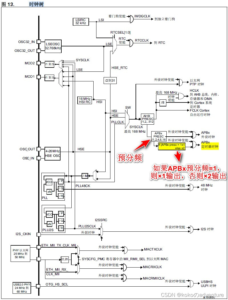
2.2 时钟树
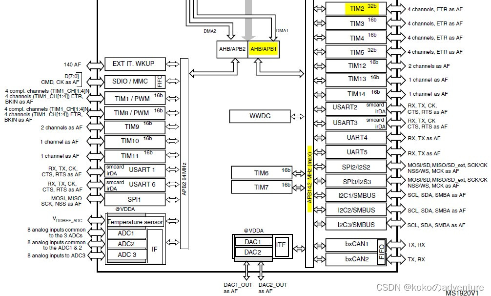
查STM32F407中文手册392页可找到如下图片:
| 系统时钟频率=168MHz | ||
| 时钟总线 | 时钟总线的时钟标记名 | 允许最大频率 |
| AHB | HCLK | 168MHz |
| APB1(低速) | PCLK1 | 42MHz |
| APB2(高速) | PCLK2 | 84MHz |
从图中可以看出,定时器的时钟不是直接来自APB1或APB2,而是来自于输入为APB1或APB2的一个倍频器。
下面以定时器2~7的时钟说明这个倍频器的作用:
① 当APB1的预分频系数为1时,这个倍频器不起作用,定时器的时钟频率等于APB1的频率;
② 当APB1的预分频系数为其它数值(即预分频系数为2、4、8或16)时,这个倍频器起作用,定时器的时钟频率等于APB1的频率两倍。
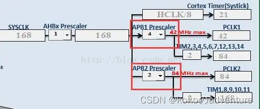
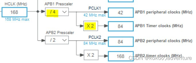
通过调整预分频系数:
我们发现:
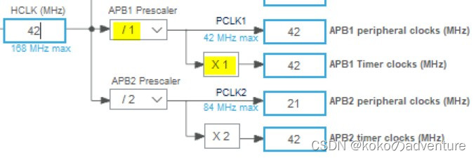
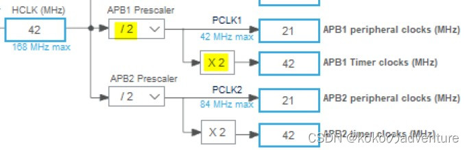
假定AHB = 42MHz,因为APB1允许的最大频率为42MHz,所以APB1的预分频系数可以取任意数值:当预分频系数 = 1时,APB1 = 42MHz,TIM2~7的时钟频率 = 42MHz(倍频器不起作用);当预分频系数 = 2时,APB1 = 21MHz,在倍频器的作用下,TIM2~7的时钟频率 = 42MHz。
有人会问,既然需要TIM2~7的时钟频率 = 42MHz,为什么不直接取APB1的预分频系数=1呢?答案是:APB1不但要为TIM2~7提供时钟,而且还要为其它外设提供时钟;设置这个倍频器可以在保证其它外设使用较低时钟频率时,TIM2~7仍能得到较高的时钟频率。
再举个例子:当AHB = 84MHz时,APB1的预分频系数必须大于等于2,因为APB1的最大频率只能为42MHz。如果APB1的预分频系数 = 2,则因为这个倍频器,TIM2~7仍然能够得到72MHz的时钟频率。能够使用更高的时钟频率,无疑提高了定时器的分辨率,这也正是设计这个倍频器的初衷。
STM32F407VET6数据手册17页可看到图片如下:
下方有英文说明:The timers connected to APB2 are clocked from TIMxCLK up to 168 MHz, while the timers connected to APB1 are clocked from TIMxCLK up to 84 MHz.
翻译知:连接到APB2的定时器由TIMxCLK提供时钟,最高可达168MHz,而连接到APB1的定时器由TIMxCLK提供时钟,最高可达84MHz。
名词解释
PRESC (Prescaler):预分频器,用来将定时器时钟源进行分频输出
AHB (Advanced High Performance Bus):高级高性能总线
APB (Advanced Peripheral Bus):(高级)外围总线
【另:RCC(Reset clock Control 复位时钟控制器)、时钟总线、Sys Tick时钟(系统定时器)、系统时钟源、PLL配置、相关常用函数(标准库)等概念知识见博客STM32的时钟系统学习笔记(基于STM32F407)_我电子贼菜的博客-CSDN博客
、基于STM32F407时钟配置学习 - 爱码网 (likecs.com)及STM32学习笔记(五)RCC(Reset and Clock Control) - 简书 (jianshu.com)】
3 软件配置
STM32CubeMX配置
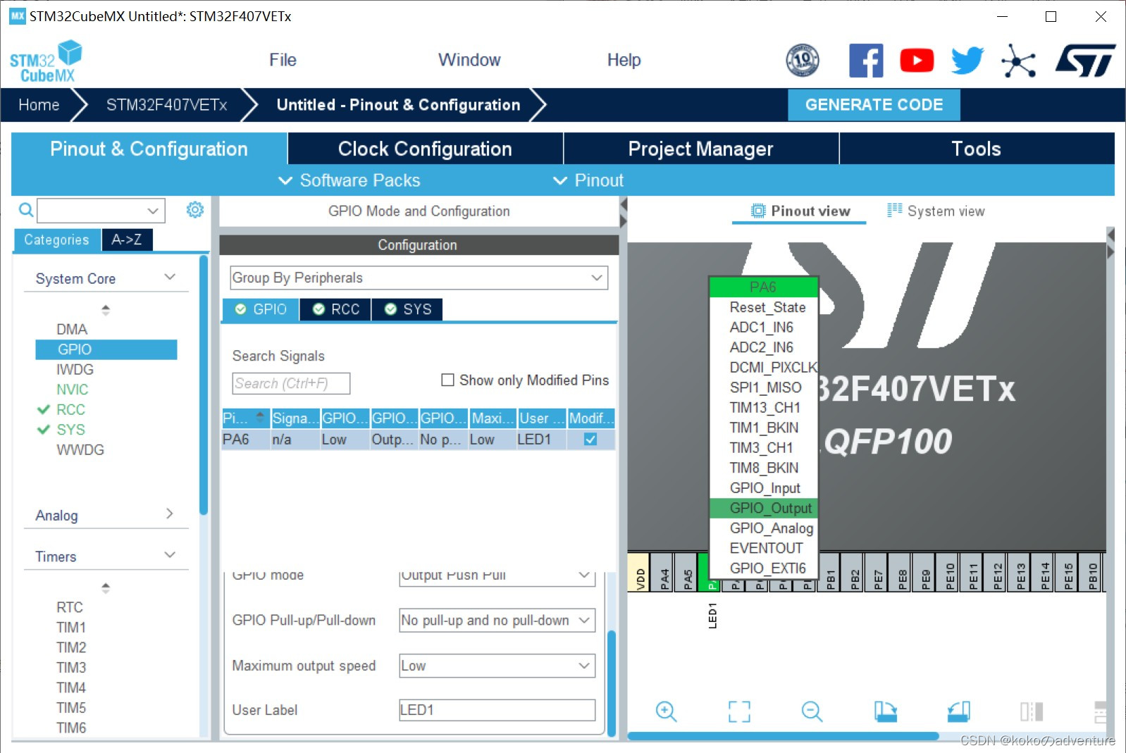
3.1 配置GPIO
选择PA6
3.2 配置定时器TIM2
由2.2分析可知,TIM2内部时钟来源是PCLK1 = 84MHz,预分频系数(PSC)设置为:83(即84 - 1),则84 000 000 / 84 = 1MHz,即每秒计数1M次,即每秒产生个脉冲。
为使每0.5s产生1次中断,则经过(即0.5/1 *
)次脉冲就应重新开始计数,则自动重装值(AutoReload Register,简称ARR)为499999(即
)。
可进行公式推导:
所以有公式归纳如下:
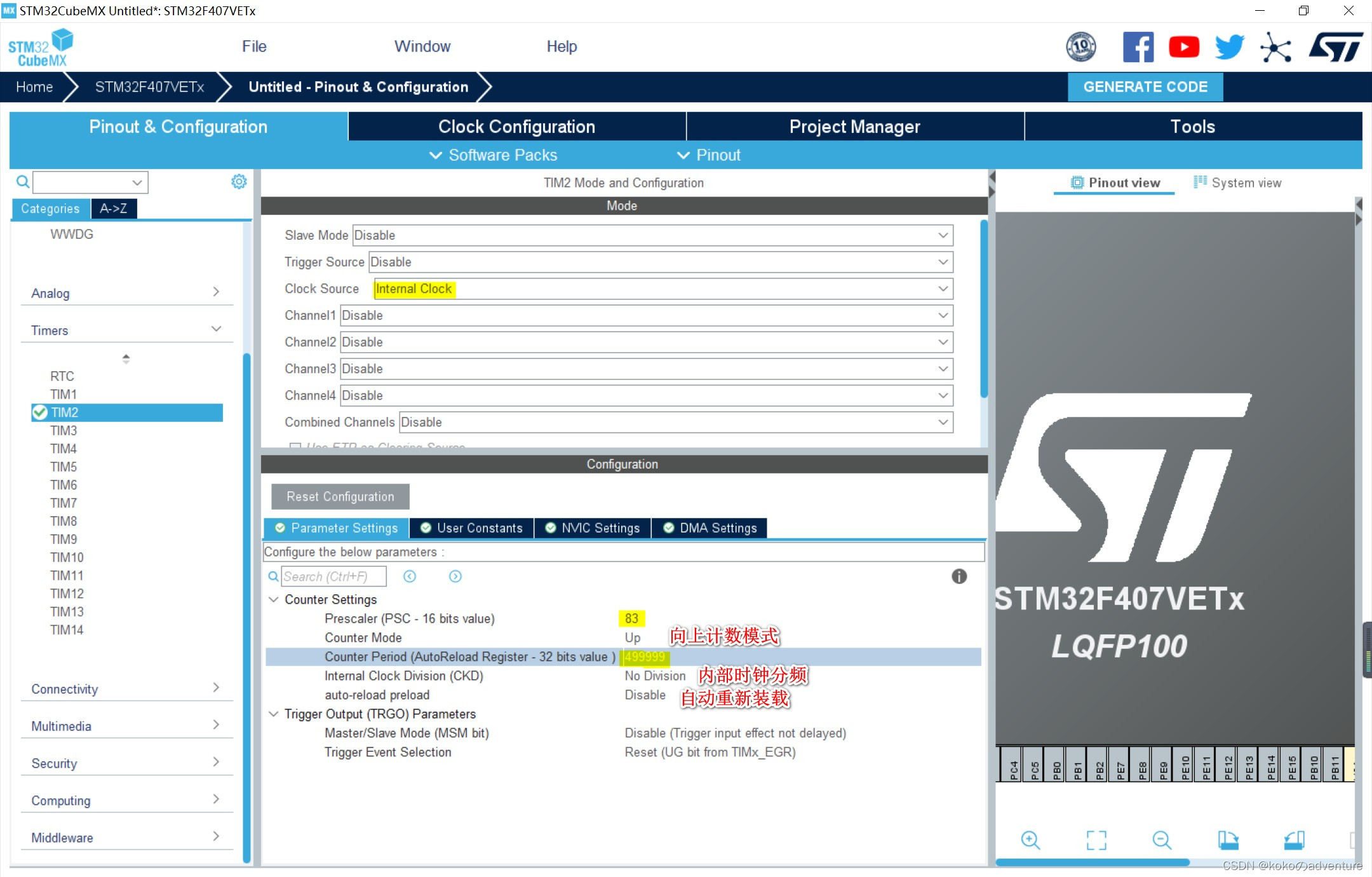
预分频系数设置为83,自动重载值为499999,得到的计时器更新中断频率即为2Hz。
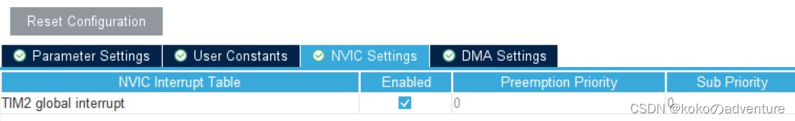
打开中断:
4 代码编写
【该部分摘自博客【STM32Cube_11】使用通用定时器闪烁LED_Mculover666的博客】
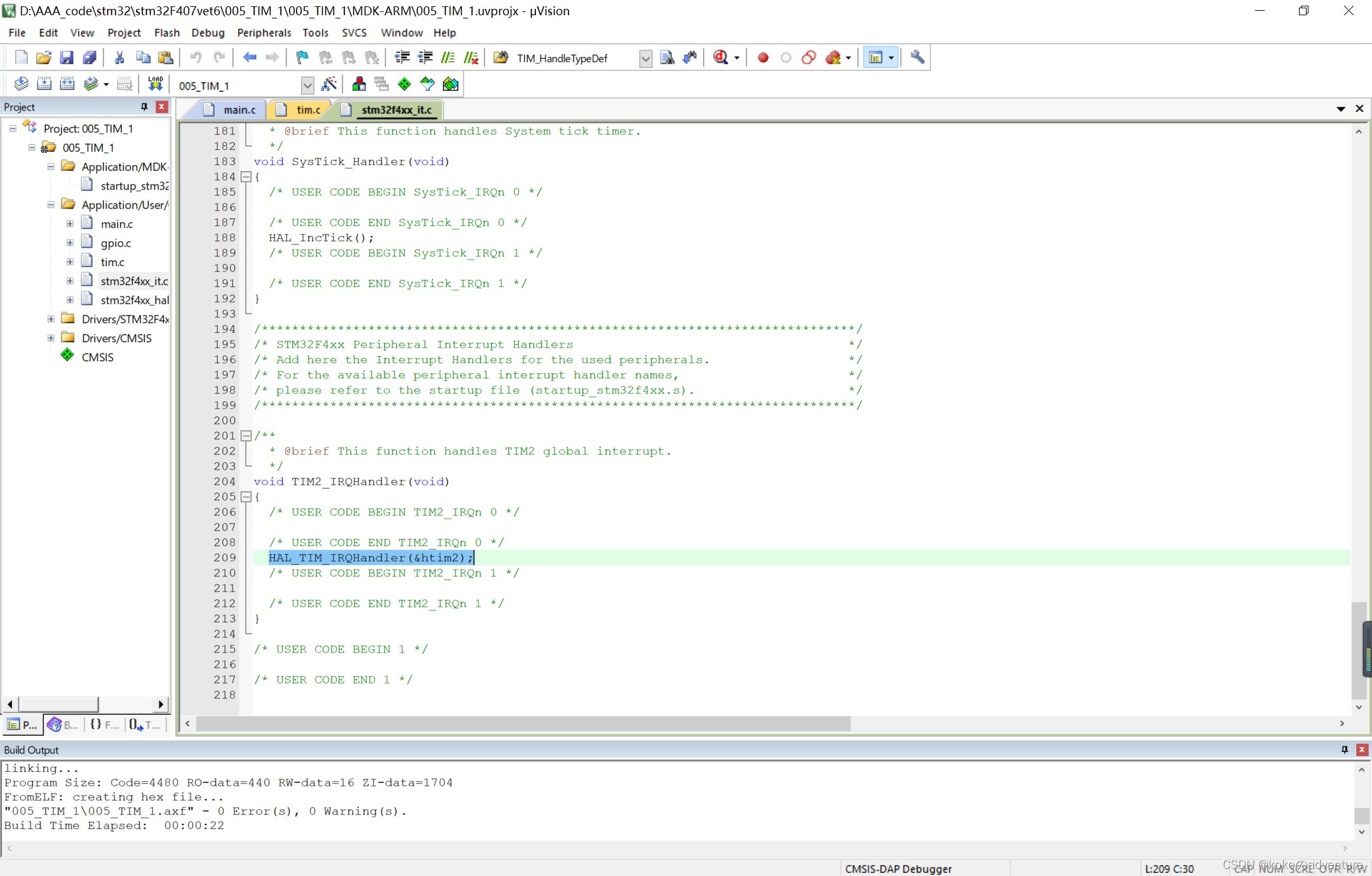
在stm32f4xx_it.c中生成的中断处理函数如下,定时器TIM2所有的中断都会调用该中断服务函数TIM2_IRQHandler:
/**
*@brief 这个函数处理TIM中断请求。
* @param htim TIM handle
* @retval 无
*/void HAL_TIM_IRQHandler(TIM_HandleTypeDef *htim)
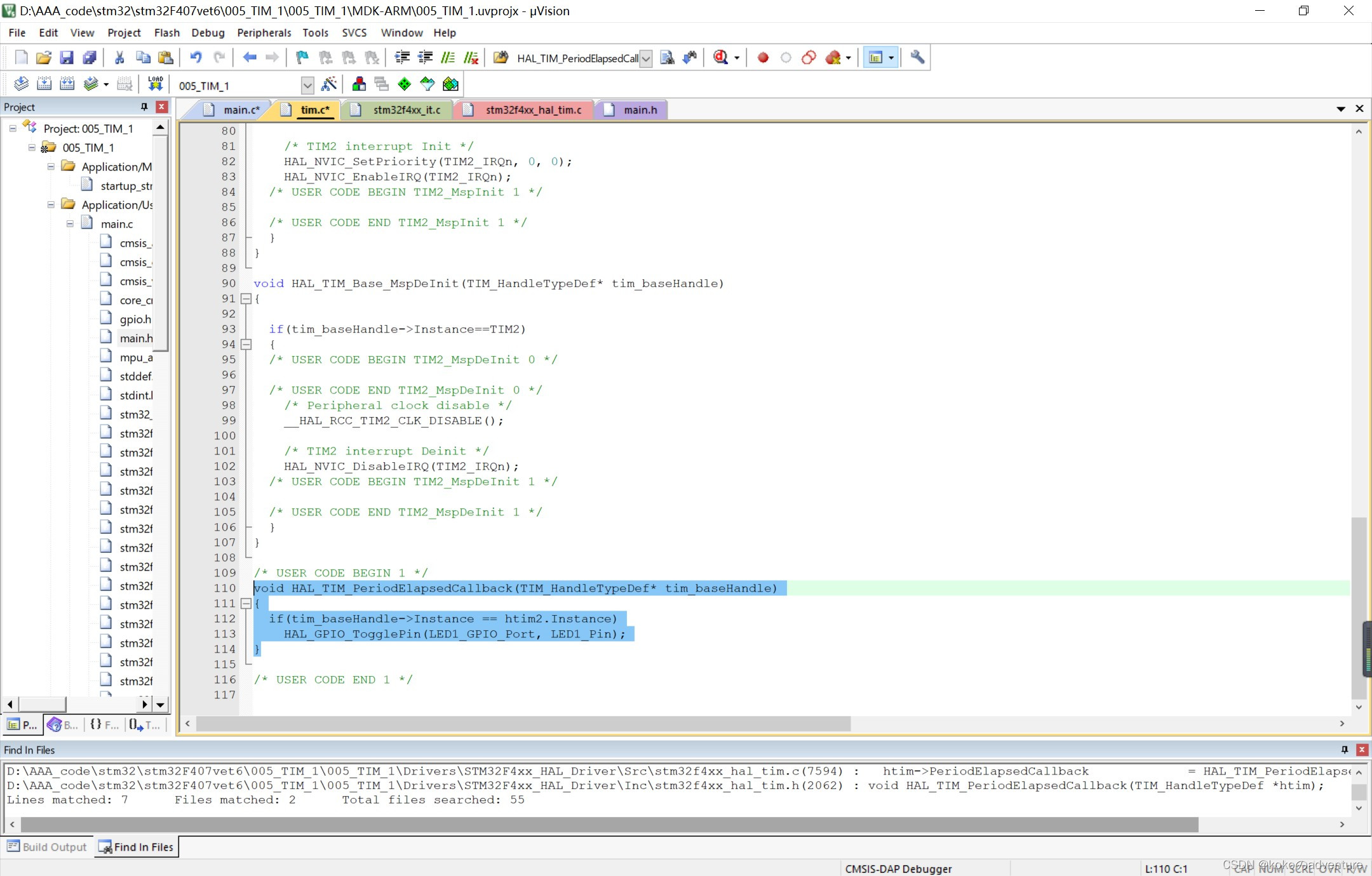
在中断处理函数中自动生成了HAL_TIM_IRQHandler(&htim2)代码,该代码会自动根据中断事件回调相应的函数,这里我们需要处理更新中断的事件,回调函数默认是__weak定义的,所以在tim.c中重新定义该回调函数,并且在该函数中添加功能的时候,因为该回调函数会被所有的定时器共用,所以需要先判断是哪个定时器在调用:
void HAL_TIM_PeriodElapsedCallback(TIM_HandleTypeDef* tim_baseHandle)
{
	if(tim_baseHandle->Instance == htim2.Instance)
		HAL_GPIO_TogglePin(LED1_GPIO_Port, LED1_Pin);
}
最后在main函数中开启TIM2并使能其中断(TIM2初始化代码之后,while之前):
HAL_TIM_Base_Start_IT(&htim2);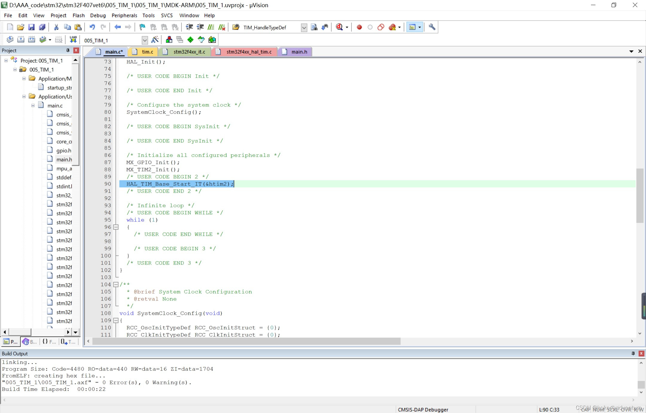 最后编译下载
【相关库函数见【STM32】HAL库学习 3—hal_time_kokoのadventure的博客-CSDN博客】
总代码如下:
main.c
/* USER CODE BEGIN Header */
/**
  ******************************************************************************
  * @file           : main.c
  * @brief          : Main program body
  ******************************************************************************
  * @attention
  *
  * Copyright (c) 2022 STMicroelectronics.
  * All rights reserved.
  *
  * This software is licensed under terms that can be found in the LICENSE file
  * in the root directory of this software component.
  * If no LICENSE file comes with this software, it is provided AS-IS.
  *
  ******************************************************************************
  */
/* USER CODE END Header */
/* Includes ------------------------------------------------------------------*/
#include "main.h"
#include "tim.h"
#include "gpio.h"

/* Private includes ----------------------------------------------------------*/
/* USER CODE BEGIN Includes */

/* USER CODE END Includes */

/* Private typedef -----------------------------------------------------------*/
/* USER CODE BEGIN PTD */

/* USER CODE END PTD */

/* Private define ------------------------------------------------------------*/
/* USER CODE BEGIN PD */
/* USER CODE END PD */

/* Private macro -------------------------------------------------------------*/
/* USER CODE BEGIN PM */

/* USER CODE END PM */

/* Private variables ---------------------------------------------------------*/

/* USER CODE BEGIN PV */

/* USER CODE END PV */

/* Private function prototypes -----------------------------------------------*/
void SystemClock_Config(void);
/* USER CODE BEGIN PFP */

/* USER CODE END PFP */

/* Private user code ---------------------------------------------------------*/
/* USER CODE BEGIN 0 */

/* USER CODE END 0 */

/**
  * @brief  The application entry point.
  * @retval int
  */
int main(void)
{
  /* USER CODE BEGIN 1 */

  /* USER CODE END 1 */

  /* MCU Configuration--------------------------------------------------------*/

  /* Reset of all peripherals, Initializes the Flash interface and the Systick. */
  HAL_Init();

  /* USER CODE BEGIN Init */

  /* USER CODE END Init */

  /* Configure the system clock */
  SystemClock_Config();

  /* USER CODE BEGIN SysInit */

  /* USER CODE END SysInit */

  /* Initialize all configured peripherals */
  MX_GPIO_Init();
  MX_TIM2_Init();
  /* USER CODE BEGIN 2 */
	HAL_TIM_Base_Start_IT(&htim2);
  /* USER CODE END 2 */

  /* Infinite loop */
  /* USER CODE BEGIN WHILE */
  while (1)
  {
    /* USER CODE END WHILE */

    /* USER CODE BEGIN 3 */
  }
  /* USER CODE END 3 */
}

/**
  * @brief System Clock Configuration
  * @retval None
  */
void SystemClock_Config(void)
{
  RCC_OscInitTypeDef RCC_OscInitStruct = {0};
  RCC_ClkInitTypeDef RCC_ClkInitStruct = {0};

  /** Configure the main internal regulator output voltage
  */
  __HAL_RCC_PWR_CLK_ENABLE();
  __HAL_PWR_VOLTAGESCALING_CONFIG(PWR_REGULATOR_VOLTAGE_SCALE1);

  /** Initializes the RCC Oscillators according to the specified parameters
  * in the RCC_OscInitTypeDef structure.
  */
  RCC_OscInitStruct.OscillatorType = RCC_OSCILLATORTYPE_HSI;
  RCC_OscInitStruct.HSIState = RCC_HSI_ON;
  RCC_OscInitStruct.HSICalibrationValue = RCC_HSICALIBRATION_DEFAULT;
  RCC_OscInitStruct.PLL.PLLState = RCC_PLL_ON;
  RCC_OscInitStruct.PLL.PLLSource = RCC_PLLSOURCE_HSI;
  RCC_OscInitStruct.PLL.PLLM = 8;
  RCC_OscInitStruct.PLL.PLLN = 168;
  RCC_OscInitStruct.PLL.PLLP = RCC_PLLP_DIV2;
  RCC_OscInitStruct.PLL.PLLQ = 4;
  if (HAL_RCC_OscConfig(&RCC_OscInitStruct) != HAL_OK)
  {
    Error_Handler();
  }

  /** Initializes the CPU, AHB and APB buses clocks
  */
  RCC_ClkInitStruct.ClockType = RCC_CLOCKTYPE_HCLK|RCC_CLOCKTYPE_SYSCLK
                              |RCC_CLOCKTYPE_PCLK1|RCC_CLOCKTYPE_PCLK2;
  RCC_ClkInitStruct.SYSCLKSource = RCC_SYSCLKSOURCE_PLLCLK;
  RCC_ClkInitStruct.AHBCLKDivider = RCC_SYSCLK_DIV1;
  RCC_ClkInitStruct.APB1CLKDivider = RCC_HCLK_DIV4;
  RCC_ClkInitStruct.APB2CLKDivider = RCC_HCLK_DIV2;

  if (HAL_RCC_ClockConfig(&RCC_ClkInitStruct, FLASH_LATENCY_5) != HAL_OK)
  {
    Error_Handler();
  }
}

/* USER CODE BEGIN 4 */

/* USER CODE END 4 */

/**
  * @brief  This function is executed in case of error occurrence.
  * @retval None
  */
void Error_Handler(void)
{
  /* USER CODE BEGIN Error_Handler_Debug */
  /* User can add his own implementation to report the HAL error return state */
  __disable_irq();
  while (1)
  {
  }
  /* USER CODE END Error_Handler_Debug */
}

#ifdef  USE_FULL_ASSERT
/**
  * @brief  Reports the name of the source file and the source line number
  *         where the assert_param error has occurred.
  * @param  file: pointer to the source file name
  * @param  line: assert_param error line source number
  * @retval None
  */
void assert_failed(uint8_t *file, uint32_t line)
{
  /* USER CODE BEGIN 6 */
  /* User can add his own implementation to report the file name and line number,
     ex: printf("Wrong parameters value: file %s on line %d\r\n", file, line) */
  /* USER CODE END 6 */
}
#endif /* USE_FULL_ASSERT */
main.h:
/* USER CODE BEGIN Header */
/**
  ******************************************************************************
  * @file           : main.h
  * @brief          : Header for main.c file.
  *                   This file contains the common defines of the application.
  ******************************************************************************
  * @attention
  *
  * Copyright (c) 2022 STMicroelectronics.
  * All rights reserved.
  *
  * This software is licensed under terms that can be found in the LICENSE file
  * in the root directory of this software component.
  * If no LICENSE file comes with this software, it is provided AS-IS.
  *
  ******************************************************************************
  */
/* USER CODE END Header */

/* Define to prevent recursive inclusion -------------------------------------*/
#ifndef __MAIN_H
#define __MAIN_H

#ifdef __cplusplus
extern "C" {
#endif

/* Includes ------------------------------------------------------------------*/
#include "stm32f4xx_hal.h"

/* Private includes ----------------------------------------------------------*/
/* USER CODE BEGIN Includes */

/* USER CODE END Includes */

/* Exported types ------------------------------------------------------------*/
/* USER CODE BEGIN ET */

/* USER CODE END ET */

/* Exported constants --------------------------------------------------------*/
/* USER CODE BEGIN EC */

/* USER CODE END EC */

/* Exported macro ------------------------------------------------------------*/
/* USER CODE BEGIN EM */

/* USER CODE END EM */

/* Exported functions prototypes ---------------------------------------------*/
void Error_Handler(void);

/* USER CODE BEGIN EFP */

/* USER CODE END EFP */

/* Private defines -----------------------------------------------------------*/
#define LED1_Pin GPIO_PIN_6
#define LED1_GPIO_Port GPIOA
/* USER CODE BEGIN Private defines */

/* USER CODE END Private defines */

#ifdef __cplusplus
}
#endif

#endif /* __MAIN_H */
tim.c:
/* USER CODE BEGIN Header */
/**
  ******************************************************************************
  * @file    tim.c
  * @brief   This file provides code for the configuration
  *          of the TIM instances.
  ******************************************************************************
  * @attention
  *
  * Copyright (c) 2022 STMicroelectronics.
  * All rights reserved.
  *
  * This software is licensed under terms that can be found in the LICENSE file
  * in the root directory of this software component.
  * If no LICENSE file comes with this software, it is provided AS-IS.
  *
  ******************************************************************************
  */
/* USER CODE END Header */
/* Includes ------------------------------------------------------------------*/
#include "tim.h"

/* USER CODE BEGIN 0 */

/* USER CODE END 0 */

TIM_HandleTypeDef htim2;

/* TIM2 init function */
void MX_TIM2_Init(void)
{

  /* USER CODE BEGIN TIM2_Init 0 */

  /* USER CODE END TIM2_Init 0 */

  TIM_ClockConfigTypeDef sClockSourceConfig = {0};
  TIM_MasterConfigTypeDef sMasterConfig = {0};

  /* USER CODE BEGIN TIM2_Init 1 */

  /* USER CODE END TIM2_Init 1 */
  htim2.Instance = TIM2;
  htim2.Init.Prescaler = 83;
  htim2.Init.CounterMode = TIM_COUNTERMODE_UP;
  htim2.Init.Period = 499999;
  htim2.Init.ClockDivision = TIM_CLOCKDIVISION_DIV1;
  htim2.Init.AutoReloadPreload = TIM_AUTORELOAD_PRELOAD_DISABLE;
  if (HAL_TIM_Base_Init(&htim2) != HAL_OK)
  {
    Error_Handler();
  }
  sClockSourceConfig.ClockSource = TIM_CLOCKSOURCE_INTERNAL;
  if (HAL_TIM_ConfigClockSource(&htim2, &sClockSourceConfig) != HAL_OK)
  {
    Error_Handler();
  }
  sMasterConfig.MasterOutputTrigger = TIM_TRGO_RESET;
  sMasterConfig.MasterSlaveMode = TIM_MASTERSLAVEMODE_DISABLE;
  if (HAL_TIMEx_MasterConfigSynchronization(&htim2, &sMasterConfig) != HAL_OK)
  {
    Error_Handler();
  }
  /* USER CODE BEGIN TIM2_Init 2 */

  /* USER CODE END TIM2_Init 2 */

}

void HAL_TIM_Base_MspInit(TIM_HandleTypeDef* tim_baseHandle)
{

  if(tim_baseHandle->Instance==TIM2)
  {
  /* USER CODE BEGIN TIM2_MspInit 0 */

  /* USER CODE END TIM2_MspInit 0 */
    /* TIM2 clock enable */
    __HAL_RCC_TIM2_CLK_ENABLE();

    /* TIM2 interrupt Init */
    HAL_NVIC_SetPriority(TIM2_IRQn, 0, 0);
    HAL_NVIC_EnableIRQ(TIM2_IRQn);
  /* USER CODE BEGIN TIM2_MspInit 1 */

  /* USER CODE END TIM2_MspInit 1 */
  }
}

void HAL_TIM_Base_MspDeInit(TIM_HandleTypeDef* tim_baseHandle)
{

  if(tim_baseHandle->Instance==TIM2)
  {
  /* USER CODE BEGIN TIM2_MspDeInit 0 */

  /* USER CODE END TIM2_MspDeInit 0 */
    /* Peripheral clock disable */
    __HAL_RCC_TIM2_CLK_DISABLE();

    /* TIM2 interrupt Deinit */
    HAL_NVIC_DisableIRQ(TIM2_IRQn);
  /* USER CODE BEGIN TIM2_MspDeInit 1 */

  /* USER CODE END TIM2_MspDeInit 1 */
  }
}

/* USER CODE BEGIN 1 */
void HAL_TIM_PeriodElapsedCallback(TIM_HandleTypeDef* tim_baseHandle)
{
	if(tim_baseHandle->Instance == htim2.Instance)
		HAL_GPIO_TogglePin(LED1_GPIO_Port, LED1_Pin);
}

/* USER CODE END 1 */
tim.h:
/* USER CODE BEGIN Header */
/**
  ******************************************************************************
  * @file    tim.h
  * @brief   This file contains all the function prototypes for
  *          the tim.c file
  ******************************************************************************
  * @attention
  *
  * Copyright (c) 2022 STMicroelectronics.
  * All rights reserved.
  *
  * This software is licensed under terms that can be found in the LICENSE file
  * in the root directory of this software component.
  * If no LICENSE file comes with this software, it is provided AS-IS.
  *
  ******************************************************************************
  */
/* USER CODE END Header */
/* Define to prevent recursive inclusion -------------------------------------*/
#ifndef __TIM_H__
#define __TIM_H__

#ifdef __cplusplus
extern "C" {
#endif

/* Includes ------------------------------------------------------------------*/
#include "main.h"

/* USER CODE BEGIN Includes */

/* USER CODE END Includes */

extern TIM_HandleTypeDef htim2;

/* USER CODE BEGIN Private defines */

/* USER CODE END Private defines */

void MX_TIM2_Init(void);

/* USER CODE BEGIN Prototypes */

/* USER CODE END Prototypes */

#ifdef __cplusplus
}
#endif

#endif /* __TIM_H__ */
【本文主要参考博客:
① 【STM32Cube_11】使用通用定时器闪烁LED_Mculover666的博客-CSDN博客
② STM32普通定时器(TIM2-7)的时钟源_Dream_Chaser2015的博客-CSDN博客
③ 6.STM32F407之HAL库——定时器中断_并非凑巧的博客-CSDN博客
】
【本文仅作为个人学习记录,不出于任何商业目的。】


 1064
1064

 被折叠的 条评论
为什么被折叠?
被折叠的 条评论
为什么被折叠?
 到【灌水乐园】发言


