目录
一.操作GPIO的三个步骤
1.使用RCC开启GPIO的时钟
2.使用GPIO_Init函数初始化GPIO
3.使用输出或输入函数控制GPIO口
二.RCC函数外设时钟控制函数
1.void RCC_AHBPeriphClockCmd(uint32_t RCC_AHBPeriph, FunctionalState NewState);
2.void RCC_APB2PeriphClockCmd(uint32_t RCC_APB2Periph, FunctionalState NewState);
3.void RCC_APB1PeriphClockCmd(uint32_t RCC_APB1Periph, FunctionalState NewState);
4.FunctionalState Newstate 处选择ENABLE/DISANBLE来控制使能或失能
三.GPIO库函数
- void GPIO_DeInit(GPIO_TypeDef* GPIOx);//指定GPIO外设会被复位
- void GPIO_AFIODeInit(void);//复位AFIO外设
- void GPIO_Init(GPIO_TypeDef* GPIOx, GPIO_InitTypeDef* GPIO_InitStruct);//初始化GPIO外设
- void GPIO_StructInit(GPIO_InitTypeDef* GPIO_InitStruct);//结构体变量赋一个默认值
- uint8_t GPIO_ReadInputDataBit(GPIO_TypeDef* GPIOx, uint16_t GPIO_Pin);
- uint16_t GPIO_ReadInputData(GPIO_TypeDef* GPIOx);
- uint8_t GPIO_ReadOutputDataBit(GPIO_TypeDef* GPIOx, uint16_t GPIO_Pin);
- uint16_t GPIO_ReadOutputData(GPIO_TypeDef* GPIOx);
- void GPIO_SetBits(GPIO_TypeDef* GPIOx, uint16_t GPIO_Pin);
- void GPIO_ResetBits(GPIO_TypeDef* GPIOx, uint16_t GPIO_Pin);
- void GPIO_WriteBit(GPIO_TypeDef* GPIOx, uint16_t GPIO_Pin, BitAction BitVal);
- void GPIO_Write(GPIO_TypeDef* GPIOx, uint16_t PortVal);
* 5~8为读取函数 9~12为写入函数
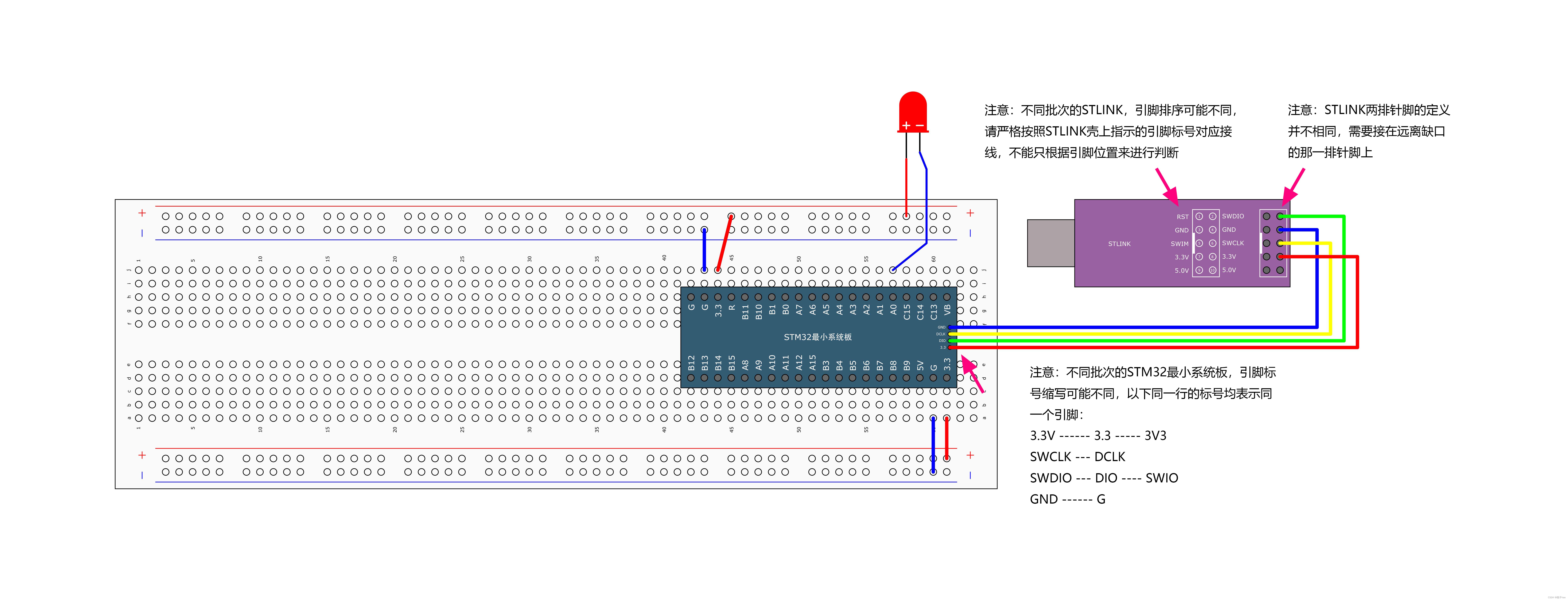
四.实验:LED闪烁

接线图
#include "stm32f10x.h"                  // Device header
#include "Delay.h"

int main(void)
{
	RCC_APB2PeriphClockCmd(RCC_APB2Periph_GPIOA,ENABLE);//RCC控制APB2外设时钟

	GPIO_InitTypeDef GPIO_InitStructure;//定义GPIO结构体变量
	GPIO_InitStructure.GPIO_Pin = GPIO_Pin_0;//选择引脚
	GPIO_InitStructure.GPIO_Speed = GPIO_Speed_50MHz;//选择输出速率
	GPIO_InitStructure.GPIO_Mode = GPIO_Mode_Out_PP;//选择输出模式

    GPIO_Init(GPIOA,&GPIO_InitStructure);
	//读取结构体 取地址符别忘

	while(1)
	{
		GPIO_WriteBit (GPIOA,GPIO_Pin_0,(BitAction)0);
		Delay_ms(100);
		GPIO_WriteBit (GPIOA,GPIO_Pin_0,(BitAction)1);
		Delay_ms(100);
	}
}
五.GPIO工作模式函数
- GPIO_Mode_AIN = 0x0 //模拟输入
- GPIO_Mode_IN_FLOATING = 0x04 //浮空输入
- GPIO_Mode_IPD = 0x28 //下拉输入
- GPIO_Mode_IPU = 0x48 //上拉输入
- GPIO_Mode_Out_OD = 0x14 //开漏输出
- GPIO_Mode_Out_PP = 0x10 //推挽输出
- GPIO_Mode_AF_OD = 0x1C //复用开漏
- GPIO_Mode_AF_PP = 0x18 //复用推挽
六.GPIO的输出函数
1.void GPIO_SetBits(GPIO_TypeDef* GPIOx, uint16_t GPIO_Pin);
将指定函数输出高电平
GPIO_Setbits(GPIOA,GPIO_Pin_0);此时PA0输出高电平 以LED闪烁为例 此时LED被熄灭。
2. void GPIO_ResetBits(GPIO_TypeDef* GPIOx, uint16_t GPIO_Pin);
将指定函数输出低电平
GPIO_ResetBit(GPIOA,GPIO_Pin_0);此时PA0输出低电平 以LED闪烁为例 此时LED被点亮。
3.void GPIO_WriteBit(GPIO_TypeDef* GPIOx, uint16_t GPIO_Pin, BitAction BitVal);
GPIO_WriteBit (GPIOA,GPIO_Pin_0,(BitAction)1);GPIO_WriteBit (GPIOA,GPIO_Pin_0,Bit_SET);以上两种功能相同 都是使PA0口输出高电平
GPIO_WriteBit (GPIOA,GPIO_Pin_0,(BitAction)0);GPIO_WriteBit (GPIOA,GPIO_Pin_0,Bit_RESET);以上两种功能相同 都是使PA0口输出低电平
(BitAction)强制类型转换
根据第三个参数的值来设置指定端口输出特定电平
4.void GPIO_Write(GPIO_TypeDef* GPIOx, uint16_t PortVal);
可以同时对16个端口进行写入操作,可参考流水灯实验
七.实验:LED流水灯

接线图
#include "stm32f10x.h"                  // Device header
#include "Delay.h"

int main(void)
{
	RCC_APB2PeriphClockCmd(RCC_APB2Periph_GPIOA,ENABLE);
	GPIO_InitTypeDef GPIO_InitStructure;
	GPIO_InitStructure.GPIO_Pin = GPIO_Pin_All;//选择全部端口
    //GPIO_InitStructure.GPIO_Pin = GPIO_Pin_0 | GPIO_Pin_1 | GPIO_Pin_2;
	GPIO_InitStructure.GPIO_Speed = GPIO_Speed_50MHz;
	GPIO_InitStructure.GPIO_Mode = GPIO_Mode_Out_PP;
	GPIO_Init(GPIOA,&GPIO_InitStructure);
	//读取结构体 取地址符别忘

	while(1)
	{
		GPIO_Write(GPIOA,~0x0001);//0000 0000 0000 0001
		Delay_ms(500);
		GPIO_Write(GPIOA,~0x0002);//0000 0000 0000 0010
		Delay_ms(500);
		GPIO_Write(GPIOA,~0x0004);
		Delay_ms(500);
		GPIO_Write(GPIOA,~0x0008);
		Delay_ms(500);
		GPIO_Write(GPIOA,~0x0010);
		Delay_ms(500);
		GPIO_Write(GPIOA,~0x0020);
		Delay_ms(500);
	}
}
我实际点亮的是6个LED 并非接线图中的8个LED
八.实验:蜂鸣器

接线图
*A15 B3 B4默认为JTAG的调试端口 不能直接使用
#include "stm32f10x.h"                  // Device header
#include "Delay.h"

int main(void)
{
	//RCC_APB2PeriphClockCmd(RCC_APB2Periph_GPIOA,ENABLE);
	RCC_APB2PeriphClockCmd(RCC_APB2Periph_GPIOB,ENABLE);

	GPIO_InitTypeDef GPIO_InitStructure;
	GPIO_InitStructure.GPIO_Pin = GPIO_Pin_12;
	GPIO_InitStructure.GPIO_Speed = GPIO_Speed_50MHz;
	GPIO_InitStructure.GPIO_Mode = GPIO_Mode_Out_PP;
	GPIO_Init(GPIOB,&GPIO_InitStructure);
	//取地址符别忘

	while(1)
	{
		GPIO_WriteBit (GPIOB,GPIO_Pin_12,(BitAction)0);
		Delay_ms(100);
		GPIO_WriteBit (GPIOB,GPIO_Pin_12,(BitAction)1);
		Delay_ms(100);
	}
}
九.补充
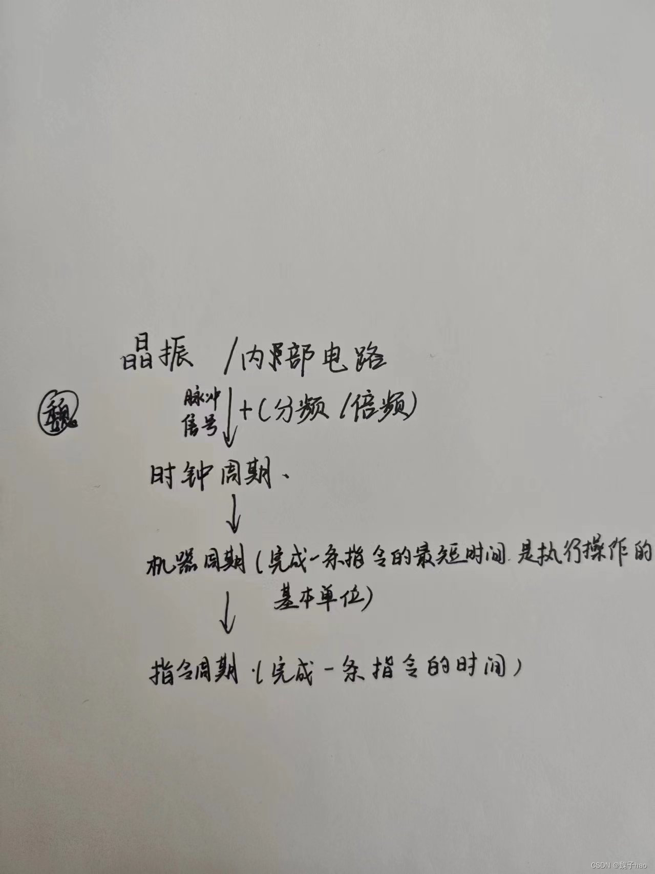
以下是借助网络,纯个人对于时钟理解 如有错误麻烦指出

时钟周期是读取存储器的时间,它在告诉单片机多少时间执行一条指令,什么时候跳向下一条指令,如果不给单片机设置时钟周期,单片机就会像“聋子”一样,不知道多久可以往下执行程序。因此说时钟是“单片机的心脏”也是可以理解的。


 1638
1638


 被折叠的 条评论
为什么被折叠?


