


 本文概述了光学器件中关键的生产规格如直径公差、中心厚度公差,以及表面规格如表面质量、表面平面度等。了解这些参数对设计和制造光学元件至关重要,影响性能和成本控制。还介绍了材料规格如折射率和色散系数,以及激光损伤阈值等重要指标。
由于近来工作需要,需要接触很多光学器件,如透镜,滤波片等等,里面很多的光学参数看得一头雾水,幸好在网上找到了一篇由光学器件大厂Edmund提供的科普文,特记录下来,以备后续参考查阅。原文是英文的,Edmund提供了中文翻译版,个人感觉,如果想要准确把握含义,需以英文为准,英文有些单词和语法的含义非常微妙,翻译成中文时会有不可避免的信息遗漏,但是中文可以快速了解,节省时间。不过Edmund网站做的很人性化,如果不改变网站提供的区域选项,默认都是提供中文版,所以文章下面贴出了中英文对照。
原文地址如下:了解光学参数规格
在元件或系统的设计和生产过程中利用光学参数规格可使该元件或系统精确达到特定的性能要求。 光学参数规格非 常有用,原因有以下两点: 首先,它们可以指定决定系统性能的可接受的关键参数限值;其次,它们能够确定应花在生产上的资源的数量(即时间和成本)。
Optical specifications are utilized throughout the design and manufacturing of a component or system to characterize how well it meets certain performance requirements. They are useful for two reasons: first, they specify the acceptable limits of key parameters that govern system performance; second, they specify the amount of resources (i.e. time and cost) that should be spent on manufacturing.
光学系统的参数规格过低或过高都会影响其性能,从而造成不必要的资源浪费。如果未正确设定所有必要的参数,则会导致规格过低,从而使性能降低。 如果过于严格地定义系统参数而不考虑光学或机械要求中的任 何变化,则会导致规格过高,从而使成本和生产难度增加。
An optical system can suffer from either under-specification or over-specification, both of which can result in unnecessary expenditure of resources. Under-specification occurs when not all of the necessary parameters are properly defined, resulting in inadequate performance. Over-specification occurs when a system is defined too tightly without any consideration for changes in optical or mechanical requirements, resulting in higher cost and increased manufacturing difficulty.
为了了解光学规格,首先弄清楚它们的含义是非常重要的。 为了简化日益繁多的数字,请考虑为透镜、 反射镜和窗口片使用最常用的生产规格、表面规格和材料规格。 滤光片、偏振片、棱镜、分光镜、光栅和 光纤也具有许多这类光学规格,因此了解最常用的规格将为 您了解几乎所有光学产品的规格提供最坚实的基础。
In order to understand optical specifications, it is important to first review what they mean. To simplify the ever-growing number, consider the most common manufacturing, surface, and material specifications for lenses, mirrors, and windows. Filters, polarizers, prisms, beamsplitters, gratings, and fiber optics also share many of these optical specifications, so understanding the most common specifications will provide a great baseline for understanding nearly all optical products.
生产规格 (Manufacturing Specifications)
直径公差 (Diameter Tolerance)
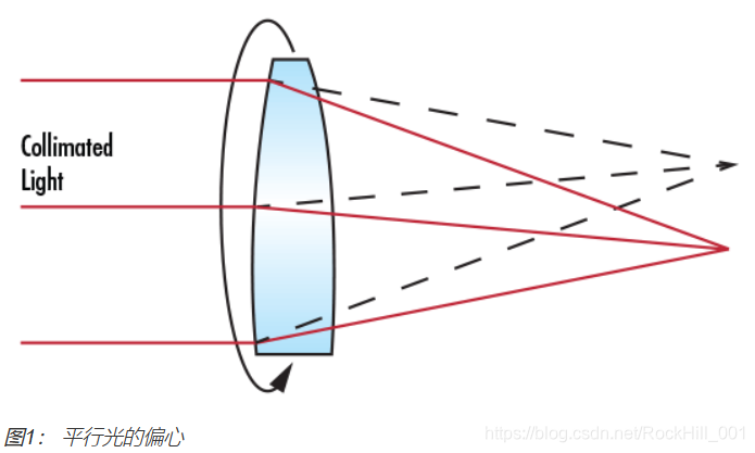
圆形光学元件的直径公差提供了一个可接受的直径值范围。 此生产规格会因制作光学产品的某些光学加工公司的技术水平和能力而有所不同。虽然直径公差不会对光学产品本身的光学性能产生任何影响,但如果要在任何一种固定器上安装光学产品,则它是您必须考虑的一种非常重要的机械公差。 例如,如果透镜的直径与其标称值存有偏差,则有可能使已安装的组件中的机械轴偏离光学轴,从而导致光的偏心(图1)。 通常,直径的生产公差为:+0.00/-0.10 mm表示一般质量,+0.00/-0.050 mm表示精密质量,+0.000/-0.010 mm则为高质量.
The diameter tolerance of a circular optical component provides the acceptable range of values for the diameter. This manufacturing specification can vary based on the skill and capabilities of the particular optical shop that is fabricating the optic. Although diameter tolerance does not have any effect on the optical performance of the optic itself, it is a very important mechanical tolerance that must be considered if the optic is going to be mounted in any type of holder. For instance, if the diameter of an optical lens deviates from its nominal value it is possible that the mechanical axis can be displaced from the optical axis in a mounted assembly, thus causing decenter (Figure 1). Typical manufacturing tolerances for diameter are: +0.00/-0.10 mm for typical quality, +0.00/-0.050 mm for precision quality, and +0.000/-0.010 mm for high quality.
中心厚度公差 (Center Thickness Tolerance)
光学元件(最典型的是透镜)的中心厚度,测量的是光学元件中心部分的材料厚度。中心厚度是通过透镜的机械轴来测量的,该机械轴是作为透镜外部边缘之间的轴来定义的。 透镜中心厚度的变化会影响光学性 能,这是因为中心厚度及其曲率半径会决定光线穿过透镜的光学路径长度。通常,中心厚度的生产公差为: +/-0.20 mm表示一般质量,+/-0.050 mm表示精密质量,+/-0.010 mm则为高质量.
The center thickness of an optical component, most notably a lens, is the material thickness of the component measured at the center. Center thickness is measured across the mechanical axis of the lens, defined as the axis exactly between its outer edges. Variation of the center thickness of a lens can affect the optical performance because center thickness, along with radius of curvature, determines the optical path length of rays passing through the lens. Typical manufacturing tolerances for center thickness are: +/-0.20 mm for typical quality, +/-0.050 mm for precision quality, and +/-0.010 mm for high quality.
曲率半径 (Radius of Curvature)
曲率半径是指光学元件的顶点与曲率中心之间的距离。该半径可以为正值、零或负值,具体要取决于该表面是凸面、平面还是凹面。如果知道曲率半径值,则可以确定光线穿过透镜或反射镜的光学路径长度,同时还对表面功率起着重要的决定作用。 曲率半径的生产容差通常为+/-0.5,但在精确应用中也可低至+/-0.1%,或在需要极高的质量情况下为+/-0.01%。
The radius of curvature is defined as the distance between an optical component’s vertex and the center of curvature. It can be positive, zero, or negative depending on whether the surface is convex, plano, or concave, respectfully. Knowing the value of the radius of curvature allows one to determine the optical path length of rays passing through the lens or mirror, but it also plays a large role in determining the power of the surface. Manufacturing tolerances for radius of curvature are typically +/-0.5, but can be as low as +/-0.1% in precision applications or +/-0.01% for extremely high quality needs.
中心(Centering)
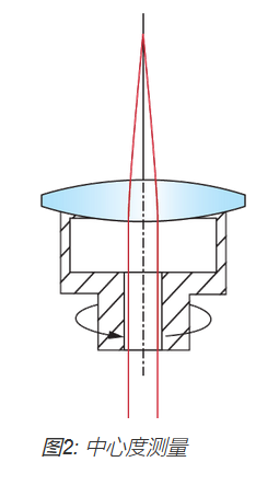
透镜的中心也称为向心性或离心性,是根据光束偏差δ(方程式1)而指定的。一旦给定了光束偏差,则可以通过一种简单的关系来计算楔角W(方程式2)。 透镜的离心量是机械轴与光学轴物理偏离的距离。透镜的机械轴仅为透镜的几何轴,是由其外部的柱面来定义的。 透镜的光学轴是由光学表面来定义的,它是连接各表面曲率中心的线。要进行向心性测试,请将透镜置于茶杯中,对其施压。 对透镜施加的压力会自动聚集在茶杯中心第一个表面的曲率中心,并且该中心还会与 旋转轴对齐(图2)。沿着此旋转轴射入的平行光将会穿过透镜,到达后焦平面的焦点处。当透镜随着茶杯的旋转而旋转时,透镜中的任何离心性都会使聚焦光束分散,并在后焦平面形成一个半径为 Δ 的圆轨迹(图1)。
Centering, also known by centration or decenter, of a lens is specified in terms of beam deviation δ (Equation 1). Once beam deviation is known, wedge angle W can be calculated by a simple relation (Equation 2). The amount of decenter in a lens is the physical displacement of the mechanical axis from the optical axis. The mechanical axis of a lens is simply the geometric axis of the lens and is defined by its outer cylinder. The optical axis of a lens is defined by the optical surfaces and is the line that connects the centers of curvature of the surfaces. To test for centration, a lens is placed into a cup upon which pressure is applied. The pressure applied to the lens automatically situates the center of curvature of the first surface in the center of the cup, which is also aligned with the axis of rotation (Figure 2). Collimated light directed along this axis of rotation is sent through the lens and comes to a focus at the rear focal plane. As the lens is rotated by rotating the cup, any decenter in the lens will cause the focusing beam to diverge and trace out a circle of radius Δ at the rear focal plane (Figure 1).
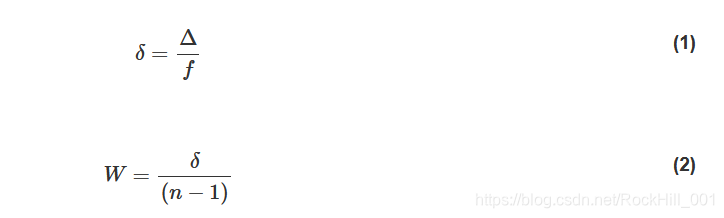 其中W表示楔角,通常报告为弧分,n表示折射率。
where W is the wedge angle, often reported as arcminutes, and n is the index of refraction.
平行度(Parallelism)
平行度描述的是两个平行表面之间的相互关系。它在指定窗口片和偏振片等元件时很有用,其中平行表面是提高系统性能的理想平面,这是因为它们可以最大限度地减少畸变,否则该畸变会降低图像或光的 质量。通常,该容差范围从5弧分直至几弧秒。
Parallelism describes how parallel two surfaces are with respect to each other. It is useful in specifying components such as windows and polarizers where parallel surfaces are ideal for system performance because they minimize distortion that can otherwise degrade image or light quality. Typical tolerances range from 5 arcminutes down to a few arcseconds.
角度公差(Angle Tolerance)
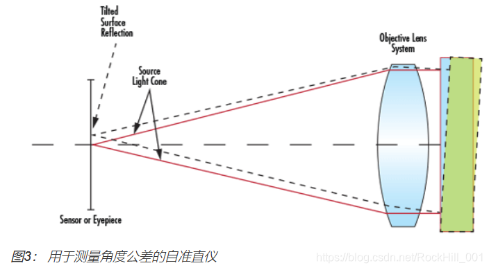
在棱镜和分光镜等元件中,各表面之间所产生的角度对光学产品的性能具有重要的影响。角度公差通常使用准直望远镜组件进行测量,其光源系统会发射平行光。 准直望远镜将围绕光学产品的表面进行旋转,直至所产生的菲涅尔反射回到该表面,在检测的表面顶部产生一个光点。这就验证了平行光束正好垂直入射到该表面。然后,整个准直望远镜组件会绕着光学产品旋转至下一个光学表面,并且会重复此过程。图3显示了用于测量角度公差的通用准直望远镜设置。可以使用两个测量位置之间的角度差来计算两个光学表面的公差。 角度公差的范围可以从几弧分降至几弧秒。
In components such as prisms and beamsplitters, the angles between surfaces are critical to the performance of the optic. This angle tolerance is typically measured using an autocollimator assembly, whose light source system emits collimated light. The autocollimator is rotated about the surface of the optic until the resultant Fresnel reflection back into it produces a spot on top of the surface under inspection. This verifies that the collimated beam is hitting the surface at exactly normal incidence. The entire autocollimator assembly is then rotated around the optic to the next optical surface and the same procedure is repeated. Figure 3 shows a typical autocollimator setup measuring angle tolerance. The difference in angle between the two measured positions is used to calculate the tolerance between the two optical surfaces. Angle tolerance can be held to tolerances of a few arcminutes all the way down to a few arcseconds.
倒角(Bevel)
玻璃角非常易碎,因此,在处理或安装元件时保护好它们非常重要。保护这些玻璃角的最常用方法是将这些边缘斜切成倒角。倒角可作为保护槽来防止边缘出现缺口。它们由其表面的宽度和角度来定义(图4)。
Glass corners can be very fragile, therefore, it is important to protect them when handling or mounting a component. The most common way of protecting these corners is to bevel the edges. Bevels serve as protective chamfers and prevent edge chips. They are defined by their face width and angle (Figure 4).
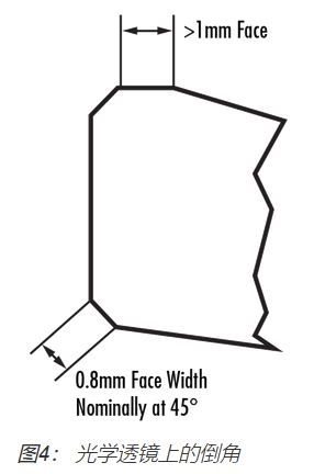
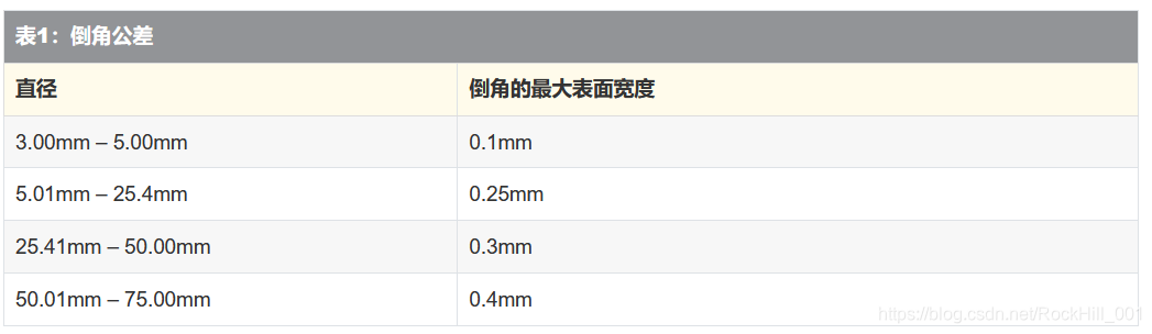
倒角的最常见切割角度为45°,并且该表面宽度是由光学产品的直径来确定的。 其直径小于3.00mm的光学产品(如微透镜或微棱镜)通常不需要切成倒角,这是因为很可能会在切削的过程中产生边缘缺口。值得注意的是,对于很小的曲率半径,例如,当透镜的直径大于等于0.85 x曲率半径时,无需切成倒角,这是因为透镜表面和边缘之间会形成很大的角度。对于所有其他直径,表1提供了最大的表面宽度。
Bevels are most commonly cut at 45° and the face width is determined by the diameter of the optic. Optics with diameters less than 3.00mm, such as micro-lenses or micro-prisms, are typically not beveled due to the likelihood of creating edge chips in the process. It is important to note that for small radii of curvature, for example, lenses where the diameter is ≥ 0.85 x radius of curvature, no bevel is needed due to the large angle between the surface and edge of the lens. For all other diameters, the maximum face widths are provided in Table 1.
通光孔径 (Clear Aperture)
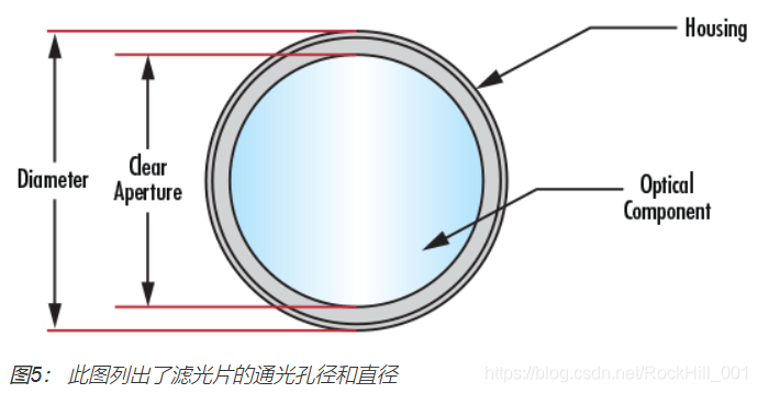
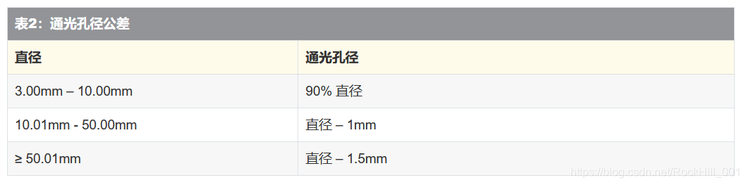
通光孔径是指光学元件的直径或必须满足各种规格的光学元件的尺寸。除通光孔径以外,制造商并不能确保光学产品符合指定的规格。由于生产的限制,实际上是不可能生产出完全等同于光学产品的直径或长乘以宽的通光孔径。表2显示了透镜的一般通光孔径。
Clear aperture is defined as the diameter or size of an optical component that must meet specifications. Outside of it, manufacturers do not guarantee the optic will adhere to the stated specifications. Due to manufacturing constraints, it is virtually impossible to produce a clear aperture exactly equal to the diameter, or the length by width, of an optic. Typical clear apertures for lenses are show in Table 2.
表面规格(Surface Specifications)
表面质量(Surface Quality)
光学表面的质量用来衡量光学产品表面特性,并且涵盖了一些划痕和坑点等瑕疵。这些表面的大部分瑕疵纯粹是表面上的瑕疵,并不会对系统性能产生很大的影响,虽然,它们可能会使系统通光量出现微小的下滑,使散射光出现更细微的散射。然而,有些表面会对这些影响更敏感,如:(1)图像平面的表面,因为这些瑕疵会产生聚焦,以及(2)具有高功率级别的表面,因为这些瑕疵会增加能量吸收并毁坏光学产品。表面质量最常用的规格是由MIL-PRF-13830B说明的划痕和坑点规格。通过将表面的划痕与在受控的照明条件下提供的一系列标准划痕进行对比,来确定划痕名称。因此,划痕名称不是描述其实际的划痕,而是根据MIL规格将其与标准的划痕进行比较。然而,坑点名称直接与表面的点或小坑有关。坑点名称是通过以微米计的坑点直径除以10来计算的,通常划痕坑点规格在80至50之间将视为标准质量,在60至40之间为精确质量,而在20至10之间将视为高精度质量。
The surface quality of an optical surface describes its cosmetic appearance and includes such defects as scratches and pits, or digs. In most cases, these surface defects are purely cosmetic and do not significantly affect system performance, though, they can cause a small loss in system throughput and a small increase in scattered light. However, certain surfaces, however, are more sensitive to these effects such as: (1) surfaces at image planes because these defects are in focus and (2) surfaces that see high power levels because these defects can cause increased absorption of energy and damage the optic. The most common specification used for surface quality is the scratch-dig specification described by MIL-PRF-13830B. The scratch designation is determined by comparing the scratches on a surface to a set of standard scratches under controlled lighting conditions. Therefore the scratch designation does not describe the actual scratch itself, but rather compares it to a standardized scratch according to the MIL-Spec. The dig designation, however, does directly relate to the dig, or small pit in the surface. The dig designation is calculated at the diameter of the dig in microns divided by 10. Scratch-dig specifications of 80-50 are typically considered standard quality, 60-40 precision quality, and 20-10 high precision quality. Learn more about surface quality here.
表面平面度(Surface Flatness)
表面平面度是一种测量表面精度的规格类型,它用于测量反射镜、窗口片、棱镜或平光镜等平面的偏差。您可以使用光学平晶来测量此偏差,该平晶是一种高质量、高精度的参考平面,用于比较试样的平滑度。当所测试的光学产品的平面靠着光学平晶放置时,会出现条纹,其形状表示所检测的光学产品的表面平滑度。如果这些条纹间隔相等,并且是平行的直线,那么被检测的光学表面至少像参考光学平晶一样平展。如果条纹是弯曲的,则两个虚线(一个虚线与条纹中点相切,另一个虚线穿过同一个条纹的端点)之间的条纹数量会指出平滑度错误。平滑度的偏差通常是按波纹值(λ)来测量的,它们是由多个波长的测试源组成。一个条纹对应½的波长。平滑度为1λ,则表示一般的质量级别;平滑度为λ/4,则表示精确的质量级别;平滑度为λ/20,表示高精度的质量级别。
Surface flatness is a type of surface accuracy specification that measures the deviation of a flat surface such as that of a mirror, window, prism, or plano-lens. This deviation can be measured using an optical flat, which is a high quality, highly precise flat reference surface used to compare the flatness of a test piece. When the flat surface of the test optic is placed against the optical flat, fringes appear whose shape dictates the surface flatness of the optic under inspection. If the fringes are evenly spaced, straight, and parallel, then the optical surface under test is at least as flat as the reference optical flat. If the fringes are curved, the number of fringes between two imaginary lines, one tangent to the center of a fringe and one through the ends of that same fringe, indicate the flatness error. The deviations in flatness are often measured in values of waves (λ), which are multiples of the wavelength of the testing source. One fringe corresponds to ½ of a wave. 1λ flatness is considered typical grade, λ/4 flatness is considered precision grade, and λ/20 is considered high precision grade.
光圈数 (Power)
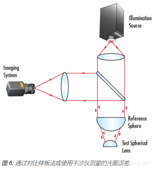
光圈数是一种测量表面精确性的规格类型,它适用于弯曲的光学表面或带有功率的表面。光圈数的测试类似于平面度测试,会将曲面与具有高校准的曲率半径的参考面进行比较。使用这两个表面空隙所产生的相同干涉原则, 条纹干涉图案用于表示测试表面与参考表面的偏差(图 6). 与参考件产生的偏差将会产生一系列的圆环,称为牛顿环. 呈现的环越多,偏差越大。暗环或亮环的数 量,而不是暗环和亮环两者的总数,等于波长误差的2倍.
Power, a type of surface accuracy specification, applies to curved optical surfaces, or surfaces with power. It is tested in a fashion similar to flatness, in that a curved surface is compared against a reference surface with a highly calibrated radius of curvature. Using the same principle of interference caused by the air gaps between the two surfaces, the interference’s pattern of fringes is used to describe the deviation of the test surface from the reference surface (Figure 6). A deviation from the reference piece will create a series of rings, known as Newton’s Rings. The more rings present, the larger the deviation. The number of dark or light rings, not the sum of both light and dark, corresponds to twice the number of waves of error.
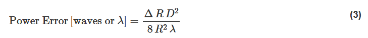
 光圈误差与曲率半径误差有关,其中 ∆R 是半径误差, D 是透镜的直径误差, R 是表面半径, 而 λ 是指波长(通常为 632.8nm):
Power error is related to the error in the radius of curvature by the following equation where ∆R is the radius error, D is the lens diameter, R is the surface radius, and λ is the wavelength (typically 632.8nm):
不规则度(Irregularity)
不规则度是一种测量表面精确性的规格类型,它描述的是表面形状与参考表面形状之间的偏差。不规则度的测量方式与光圈数相同。规则度是指将测试表面与参考表面进行比较形成的球形的圆形条纹。当表面的光圈数超过5个条纹时,将很难检测到小于1个条纹的小型不规则形状。因此,通常的做法是指定表面的光圈数与不规则度的比率,使其大约为5:1。有关光学平晶以及说明测试平面度、光圈数和不规则度的条纹图样的更多详细信息,请参阅"光学平晶"。
Irregularity, a type of surface accuracy specification, describes how the shape of a surface deviates from the shape of a reference surface. It is obtained from the same measurement as power. Regularity refers to the sphericity of the circular fringes that are formed from the comparison of the test surface to the reference surface. When the power of a surface is more than 5 fringes, it is difficult to detect small irregularities of less than 1 fringe. Therefore it is common practice to specify surfaces with a ratio of power to irregularity of approximately 5:1. For more detailed information on optical flats and interpreting fringe patterns to test surface flatness, power and irregularity, view Optical Flats
表面加工(Surface Finish)
表面加工也称为表面粗糙度,用于测量表面的一些小型不规则度。它们通常是因抛光工艺所引起的不良后果。粗糙表面往往要比光滑表面更加耐磨,并且可能不适用于某些应用,特别是在使用激光或过热环境的应用中,这是因为成核位置有可能出现细微的破裂或瑕疵。表面加工的生产容差为50Å RMS时表示一般质量,在20Å RMS时表示精确质量,而在5Å RMS时表示高质量。
Surface finish, also known as surface roughness, measures small scale irregularities on a surface. They are usually an unfortunate by-product of the polishing process. Rough surfaces tend to wear faster than smooth surfaces and may not be suitable for some applications, especially those with lasers or intense heat, due to possible nucleation sites that can appear in small cracks or imperfections. Manufacturing tolerances for surface finish range from 50Å RMS for typical quality, 20Å RMS for precision quality, and 5Å RMS for high quality.
材料规格(Material Specifications)
折射率(Index of Refraction)
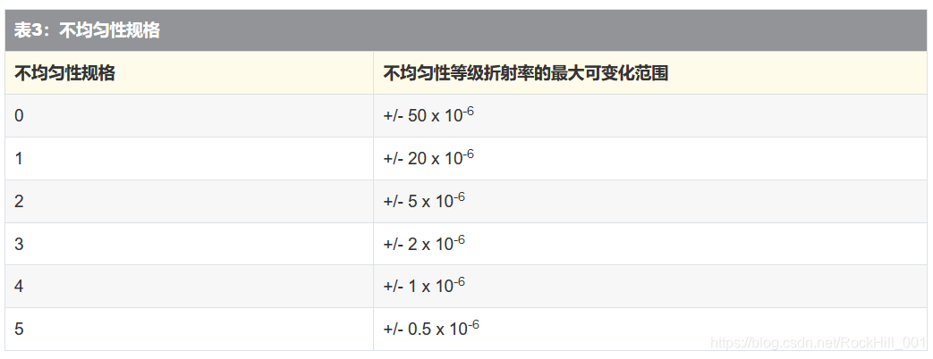
某种介质的折射率是指光在真空中的速度与光在介质中的速度之比。玻璃的折射率范围一般在1.4-4.0之间,与针对红外线优化的玻璃相比,可视玻璃的折射率范围要小一些。例如,N-BK7(一种通用的可视玻璃)的折射率为1.517,然而锗(一种通用的红外玻璃)的折射率为4.003。有关红外材料的更多信息,请参阅“红外 (IR) 应用领域使用的正确材料”。光学玻璃的折射率是一种重要属性,因为光学表面的功率是从表面的曲率半径和表面任意一侧上的介质折射率之差得来的。玻璃制造商指定的不均匀性是指玻璃折射率的变化。不均匀性是根据不同的等级来指定的,其中等级和不均匀性是互为相反关系的,随着等级的增加,不均匀性则会减少(表3)。
The index of refraction of a medium is the ratio of the speed of light in vacuum to the speed of light in the medium. Typical indices of refraction for glass range from 1.4 - 4.0; visible glasses have lower ranges than those optimized for the infrared. For example, N-BK7 (a popular visible glass) has an index of 1.517, whereas, germanium (a popular IR glass) has an index of 4.003. For more information on infrared materials, view The Correct Material for Infrared (IR) Applications. The index of refraction of an optical glass is an important property because the power of an optical surface is derived from both the radius of curvature of the surface and the difference in the index of refraction of the media on either side of the surface. Inhomogeneity, specified by the glass manufacturer, describes the variation of index of refraction in a glass. It is specified according to different classes, where class and inhomogeneity are inversely related – as class increases, inhomogeneity decreases (Table 3).
色散系数(Abbe Number)
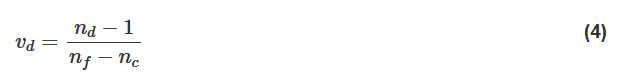
玻璃的另一种材料属性是色散系数,用于量化玻璃呈现的色散量。它是材料在f (486.1nm)、d (587.6nm) 和c (656.3nm)波长时的折射率(方程式3)。
Another material property of glasses is the Abbe number, which quantifies the amount of dispersion that a glass exhibits. It is a function of the refractive index of a material at the f (486.1nm), d (587.6nm), and c (656.3nm) wavelengths (Equation 3),
色散系数值的范围通常在25至65之间。当玻璃的色散系数大于55(较小色散)时,会将该玻璃视为冕牌玻璃,而那些色散系数小于50(较多色散)的玻璃会视为火石玻璃。由于色散性,玻璃的折射率会因波长而有所不同。色散产生的最显著结果就是系统的焦距会因不同的光波长而稍有不同。有关折射率和色散系数等重要材料规格的更多详细信息,请参阅"光学玻璃"。
Typical values of Abbe number range from 25 – 65. Glasses with an Abbe number greater than 55 (less dispersive) are considered crown glasses and those with an Abbe number less than 50 (more dispersive) are considered flint glasses. Due to dispersion, the index of refraction of a glass varies with wavelength. The most notable consequence of this is the fact that a system will have slightly different focal lengths for different wavelengths of light. For more detailed information on important material specifications such as index of refraction and Abbe number, please view Optical Glass.
激光损伤阈值(Laser Damage Threshold)
激光损伤阈值是指激光损伤前每一区域的表面可耐受的最大激光功率量。脉冲激光和连续波(CW)激光都具有相应的激光损伤阈值。激光损伤阈值是反射镜的一个非常重要的材料规格,这是因为它们与激光产品而不是任何其他光学产品一同使用,然而,任何激光级光学产品将提供阈值。例如,考虑一下Ti:蓝宝石激光反射镜的损伤额定阈值为0.5 J/cm2 @ 150飞秒脉冲和100kW/cm2 CW。这就说明反射镜每平方厘米可耐受的高重复飞秒脉冲激光射入的能量密度为0.5J,或每平方厘米可耐受的大功率CW 激光射入的能量密度为100kW。如果激光束集中在更小的区域内,则必须考虑采取相应的措施以确保整体阈值不超过指定的值。
Laser damage threshold indicates the maximum amount of laser power per area that a surface can withstand before it is damaged. Values are provided for pulsed lasers and continuous wave (CW) lasers. Laser damage threshold is a very important material specification for mirrors since they are used in conjunction with laser products more than any other optic; however, any laser-grade optic will provide a threshold. For example, consider a Ti: Sapphire Laser Mirror with damage threshold ratings of 0.5 J/cm2 @ 150 femtosecond pulses and 100kW/cm2 CW. This means that the mirror can withstand energy densities of 0.5J per square centimeter from a high repetition femtosecond pulsed laser or 100kW per square centimeter from a high power CW laser. If the laser is concentrated on a smaller region, then the proper consideration must be taken to ensure the overall threshold does not exceed the specified values.
虽然具有一系列的其他生产规格、表面规格和材料规格,但如果了解了最常用的光学规格,则可以显著地避免混淆。透镜、反射镜、窗口片、滤光片、偏振片、棱镜、分光镜、光栅、and 光纤共同具有各种属性,因此,了解它们之间的关系以及它们将如何影响整体系统性能,将有助于您选择最佳的元件以集成到光学、成像或光电子应用中。
Though a host of additional manufacturing, surface, and material specifications exist, understanding the most common optical specifications can greatly alleviate confusion. Lenses, mirrors, windows, filters, polarizers, prisms, beamsplitters, gratings, and fiber optics share a variety of attributes, therefore, knowledge of how they relate to each other and can affect overall system performance helps to choose the best components for integration into optics, imaging, or photonics applications.


 725
725

 被折叠的 条评论
为什么被折叠?
被折叠的 条评论
为什么被折叠?
 到【灌水乐园】发言


