


In Depth: Custom Shader Effects
深度:自定义着色器效果
September 05, 2022 by Eskil Abrahamsen Blomfeldt | Comments
2022年9月5日作者:艾斯基尔·阿布拉罕森·布隆费尔德 评论
Introduction
介绍
Qt Graphical Effects was one of the modules left out from the original Qt 6.0 release, unfortunately without a direct replacement at the time. There was a port available as source, but it wasn't built or included in the official releases.
Qt图形效果是最初Qt 6.0版本中遗漏的模块之一,不幸的是当时没有直接替换。有一个端口可用作源代码,但它没有构建或包含在官方版本中。
One of the reasons was that not all effects were compatible with the Qt 6 approach of precompiling shader code: Some shaders in Qt Graphical Effects are generated at run-time from the properties, to enable pregenerating tables such as Gaussian weights. With the introduction of RHI in Qt 6, we now compile shader code at build time. This can give considerable improvements for startup times and frame rate during loading, but the trade-off is that it somewhat restricts our ability to generate code on the fly.
其中一个原因是,并非所有效果都与预编译着色器代码的Qt 6方法兼容:Qt图形效果中的某些着色器在运行时根据属性生成,以启用预生成表(如高斯权重)。随着Qt 6中引入RHI,我们现在可以在构建时编译着色器代码。这可以大大提高加载期间的启动时间和帧速率,但折衷是,它在某种程度上限制了我们动态生成代码的能力。
And, in addition, we had seen over the years that there was a fundamental drawback in how the graphical effects were designed. Chaining effects requires an additional draw call, an additional set of shader passes and an additional offscreen buffer for each effect you add. This causes the chained effect to be both slower and more memory hungry than it needs to be. The end result was that users would often implement custom effects instead, in order to optimize their applications. We thought we could do better, and therefore we did not officially include Qt Graphical Effects in the first releases of Qt 6.
此外,多年来,我们发现图形效果的设计存在一个基本缺陷。链接效果需要一个额外的绘制调用、一组额外的着色器过程以及为添加的每个效果提供额外的屏幕外缓冲区。这会导致链式效应比它需要的更慢和更消耗内存。最终结果是,用户通常会实现自定义效果,以优化其应用程序。我们认为我们可以做得更好,因此我们没有正式在Qt6的第一个版本中包含Qt图形效果。

However, Qt Graphical Effects is undeniably a useful module, and many users were disappointed by its absence. After plenty of helpful feedback, we added the module back as part of the Qt 5 Compat namespace: In Qt 6.2 we added back all effects except the ones that required run-time generation of code, and now, in Qt 6.4, the remaining types have been reinstated. The module is now fully compatible with the one in Qt 5.
然而,Qt图形效果无疑是一个有用的模块,许多用户对它的缺失感到失望。在大量有用的反馈之后,我们将模块作为Qt 5 Compat命名空间的一部分添加了回来:在Qt 6.2中,我们添加了除需要运行时生成代码之外的所有效果,现在,在Qt6.4中,其余类型已经恢复。该模块现在与Qt 5中的模块完全兼容。
We are also working on what we think is a superior solution: The Qt Quick Effect Maker, as demonstrated in the Qt Contributor Summit 2022. When it is ready, this will allow you to customize your effects in a visual tool. You will hear more about this later.
我们还正在开发一个我们认为更优秀的解决方案:Qt Quick Effect生成器,如2022年Qt贡献者峰会所示。当它准备就绪时,这将允许您在可视化工具中自定义效果。稍后您将听到更多关于此的信息。
Custom Shaders
自定义着色器
While we were discussing this topic internally, I realized that we may not have bragged enough about the custom shader effect capabilities in Qt Quick lately. Qt Graphical Effects and Qt Quick Effect Maker are great utilities of convenience, but with just regular Qt Quick you already have extremely powerful graphics tools at your fingertips.
当我们在内部讨论这个话题时,我意识到最近我们可能没有充分吹嘘Qt Quick中的自定义着色器效果功能。Qt图形效果和Qt Quick Effect Maker是非常方便的实用工具,但只要使用常规的Qt Quicks,您就已经拥有了非常强大的图形工具。
It does require writing shader code, which can be daunting if you've never done it before, but once you get past the boiler plates and declaration syntax, it should actually be quite familiar to anyone who is used to programming in C++.
它确实需要编写着色器代码,如果您以前从未这样做过,这可能会令人望而生畏,但一旦您通过了入门和声明语法,任何习惯于使用C++编程的人都应该非常熟悉它。
In this blog, I will implement a custom effect which applies both a Gaussian blur and a colorization filter in a single pass, without the overhead associated with chaining Qt Graphical Effects together. I will try to explain the details as much as possible, so hopefully it can be a starting point for readers to experiment and play.
在本博客中,我将实现一个自定义效果,在一次通过中应用高斯模糊和着色过滤器,而不需要将Qt图形效果链接在一起。我将尽可能多地解释细节,希望它能成为读者实验和游戏的起点。
As a very basic introduction: Shaders are programs that are run on the GPU itself, as part of the rendering pipeline. The rendering pipeline has many different phases, and many can be customized using a shader program. In this blog, however, we will only focus on what is called the "fragment shader". For our purposes we can think of a fragment as a pixel, and I will use the terms interchangeably. The fragment shader is run for every pixel in the output, so every time a color is drawn into the scene, it is actually some fragment shader calculating which color it should be.
作为非常基本的介绍:着色器是在GPU本身上运行的程序,作为渲染管道的一部分。渲染管道有许多不同的阶段,许多阶段可以使用着色器程序进行自定义。然而,在本博客中,我们将只关注所谓的“片段着色器”。出于我们的目的,我们可以将片段视为像素,我将互换使用这些术语。片段着色器针对输出中的每个像素运行,因此每次将颜色绘制到场景中时,它实际上是一些片段着色器计算它应该是什么颜色。
Box Blur
框模糊
We will start by writing a simple box blur.
我们将从编写一个简单的框模糊开始。
The box blur algorithm works as follows: For each pixel in the output, center a square box of some configurable size (often called the kernel) on the corresponding pixel in the source and calculate the average of all the pixels in the box. This average becomes the output color.
框模糊算法的工作原理如下:对于输出中的每个像素,将一个具有某种可配置大小的正方形框(通常称为内核)置于源中相应像素的中心,并计算框中所有像素的平均值。该平均值成为输出颜色。
Shader code
着色器代码
The shader code for a box blur effect can look as follows. Our input in this case could be any rectangular Qt Quick item. In the example project, the input is an image.
框模糊效果的着色器代码如下所示。在这种情况下,我们的输入可以是任何矩形Qt Quick项。在示例项目中,输入是图像。
#version 440

layout(location = 0) in vec2 textureCoord;
layout(location = 0) out vec4 fragColor;

layout(std140, binding = 0) uniform buf {
    mat4 qt_Matrix;
    float qt_Opacity;
    vec2 pixelStep;
    int radius;
};
layout(binding = 1) uniform sampler2D src;

void main(void)
{
    vec3 sum = vec3(0.0, 0.0, 0.0);
    for (int x = -radius; x <= radius; ++x) {
        for (int y = -radius; y <= radius; ++y) {
            vec2 c = textureCoord + vec2(x, y) * pixelStep;
            sum += texture(src, c).rgb;
        }
    }

    fragColor = vec4(sum / ((radius*2 + 1) * (radius*2 + 1)), 1.0) * qt_Opacity;
}
Lets go through this line by line to see what's going on:
让我们一行一行地看一下发生了什么:
#version 440The first line just gives the version of the shader language used, and can for our purposes always be 440. Qt will compile the shader code to different byte code representations for different target graphics APIs (or to GLSL in the case of OpenGL).
第一行只是给出了所使用的着色器语言的版本,就我们的目的而言,始终可以是440。Qt将为不同的目标图形API将着色器代码编译为不同的字节码表示(或在OpenGL的情况下编译为GLSL)。
layout(location = 0) in vec2 textureCoord;The first input is the texture coordinates. The type is vec2, which means it is a vector of two components.
第一个输入是纹理坐标。类型是vec2,这意味着它是一个由两个分量组成的向量。
Behind the scenes, Qt Quick will split our source image into two triangles and pass these to the GPU for rendering. Then a vertex shader is executed (this is a shader phase that operates on the vertices rather than pixels) which calculates the texture coordinates at each vertex. The texture coordinate is the position in the source image which corresponds to the vertex. These values are interpolated for each pixel inside the triangles and then provided to the fragment shader, so that it knows exactly which pixel in the source corresponds to the current fragment it is rendering.
在幕后,Qt Quick将源图像分割成两个三角形,并将其传递给GPU进行渲染。然后执行顶点着色器(这是对顶点而不是像素进行操作的着色器阶段),计算每个顶点的纹理坐标。纹理坐标是源图像中对应于顶点的位置。这些值将为三角形内的每个像素进行插值,然后提供给片段着色器,以便它准确地知道源中的哪个像素对应于正在渲染的当前片段。
The default vertex shader in Qt Quick calculates normalized texture coordinates: textureCoord.x == 0 is at the left-most side of the input and textureCoord.x == 1 is at the right-most side.
Qt Quick中的默认顶点着色器计算归一化纹理坐标:textureCoord.x == 0位于输入的最左侧,textureCoord.x == 1位于最右侧。
The layout qualifier together with in gives the index of the varying parameter ("varying" refers to parameters that are potentially different for each pixel, interpolated from numbers calculated in the vertex shader.) Essentially we are saying that whatever the vertex shader has as its first output should be called "textureCoord" in the context of our fragment shader code, so it's important that the index matches what is predefined in Qt's default vertex shader.
layout限定符与in一起给出了变化参数的索引(“变化”指的是每个像素可能不同的参数,根据顶点着色器中计算的数字进行插值。)本质上,我们是说,顶点着色器的第一个输出应在片段着色器代码的上下文中称为“TextureCood”,因此,索引与Qt的默认顶点着色器中预定义的匹配非常重要。
Unless you write a custom vertex shader, the first varying input parameter is always the texture coordinates, and this code can be left exactly like it is.
除非编写自定义顶点着色器,否则第一个变化的输入参数始终是纹理坐标,并且此代码可以保持原样。
layout(location = 0) out vec4 fragColor;The main output is the color of the destination pixel, and we give this the name fragColor so that we can refer to it. The expected format of the output color is a vector with four components: (r, g, b, a) where each component is a normalized number between 0 and 1. If we were to set this to (1, 0, 0, 1) for instance, the output would always be fully saturated and fully opaque red.
主要输出是目标像素的颜色,我们将其命名为fragColor,以便我们可以引用它。输出颜色的预期格式是一个包含四个分量的向量:(r、g、b、a),其中每个分量都是0和1之间的归一化数。例如,如果我们将其设置为(1、0、0、1),输出将始终是完全饱和和完全不透明的红色。
This code should also remain the same for all your custom shaders.
对于所有自定义着色器,此代码也应保持相同。
layout(std140, binding = 0) uniform buf {
    mat4 qt_Matrix;
    float qt_Opacity;
    vec2 pixelStep;
    int radius;
};
In addition to the "varying" parameters, we also have "uniform" parameters. These are parameters that are set for the render pass as a whole, but remain the same for all pixels (and all vertices for that matter). As we will see later, Qt makes it very easy to pass uniform parameters to the shader effect.
除了“变化”参数之外,我们还有“统一”参数。这些参数是为整个渲染过程设置的,但对于所有像素(以及所有顶点)保持相同。正如我们将在后面看到的,Qt使得将统一参数传递到着色器效果非常容易。
The first two parameters are expected to be present in all shaders in Qt: The main MVP matrix and the opacity of the item based on its (and its ancestors') opacity in Qt Quick. The "pixelStep" and "radius" uniforms are added as specific to this shader effect.
前两个参数预计会出现在Qt中的所有着色器中:主MVP矩阵和基于Qt Quick中项目(及其祖先)不透明度的项目不透明度。“pixelStep”和“radius”统一被添加为特定于此着色器效果。
You can append new uniforms to the end of this buffer, but you can't remove the matrix or opacity properties, nor change their order.
您可以将新的uniforms附加到此缓冲区的末尾,但不能删除矩阵或不透明度属性,也不能更改它们的顺序。
layout(binding = 1) uniform sampler2D src;All uniforms of primitive types can be bundled in the uniform buffer as shown above, but textures have to be bound individually. In our case, we have a single texture, representing the source image that we want to blur.
基本类型的所有uniforms可以绑定到统一缓冲区中,如上所示,但纹理必须单独绑定。在我们的例子中,我们有一个纹理,表示要模糊的源图像。
The main function is the entry point of the shader, and the rest of the code is what actually converts the input data into a color.
主函数是着色器的入口点,其余的代码实际上是将输入数据转换为颜色。
void main(void)
{
    vec3 sum = vec3(0.0, 0.0, 0.0);
    for (int x = -radius; x <= radius; ++x) {
        for (int y = -radius; y <= radius; ++y) {
            vec2 c = textureCoord + vec2(x, y) * pixelStep;
            sum += texture(src, c).rgb;
        }
    }

    fragColor = vec4(sum / ((radius*2 + 1) * (radius*2 + 1)), 1.0) * qt_Opacity;
}
The code here sums up all pixels in the square kernel, using the built-in texture command to sample the input at specified locations.
这里的代码汇总了正方形内核中的所有像素,使用内置纹理命令在指定位置采样输入。
There is one small obstacle though: Since the texture coordinates are normalized and we don't know the size of the input, we don't actually have any way of knowing the distance from a pixel to its neighbours (if the input is 10x10, then pixels are 0.1 apart in normalized coordinates, whereas if the input is 100x100 then pixels are 0.01 units apart.)
然而,有一个小障碍:由于纹理坐标是标准化的,我们不知道输入的大小,我们实际上没有任何方法知道像素与其相邻像素之间的距离(如果输入是10x10,则像素在标准化坐标中相距0.1,而如果输入是100x100,则像素相距为0.01个单位)
To hack around this problem, we supply the normalized size of a single pixel as a uniform called "pixelStep". In our QML code, we will pass (1/imageWidth, 1/imageHeight) for this parameter.
为了解决这个问题,我们将单个像素的规格化大小作为一个称为“像素步长”的uniform值。在QML代码中,我们将为该参数传递(1/imageWidth,1/imageHeight)。
In the end we divide by the number of pixels in the sum, i.e. the area of the kernel, and thus get the average. We then assign this to our output parameter, fragColor.
最后,我们除以和中的像素数,即核的面积,从而得到平均值。然后我们将其分配给输出参数fragColor。
CMake and QML code
CMake和QML代码
For anyone used to developing Qt Quick applications, the project structure and code in the example should look familiar. One special thing to notice in the build script is the part that actually adds the shader to the project.
对于任何习惯于开发Qt Quick应用程序的人来说,示例中的项目结构和代码应该很熟悉。在构建脚本中需要注意的一点是将着色器实际添加到项目中的部分。
qt6_add_shaders(boxblurblog "shaders"
    BATCHABLE
    PRECOMPILE
    OPTIMIZED
    PREFIX
        "/"
    FILES
        "boxblur.frag"
)
This command causes the source code in "boxblur.frag" to be compiled into a .qsb file, which can later be loaded into Direct3D, Vulkan, Metal or OpenGL - whichever graphics backend happens to be active.
此命令将“boxblur.frag”中的源代码编译为.qsb文件,该文件稍后可以加载到Direct3D、Vulkan、Metal或OpenGL中,无论哪个图形后端处于活动状态。
The shader is loaded using the ShaderEffect type in Qt Quick.
使用Qt Quick中的ShaderEffect类型加载着色器。
ShaderEffect {
    property var src: bug
    property int radius: 32
    property var pixelStep: Qt.vector2d(1/src.width, 1/src.height)
    anchors.left: bug.right
    anchors.right: parent.right
    anchors.top: bug.top
    anchors.bottom: bug.bottom
    fragmentShader: "boxblur.frag.qsb"
}
We are loading the .qsb file generated by the build system.
我们正在加载构建系统生成的.qsb文件。
In addition we are defining properties for the uniforms in the shader. Qt will automatically match up QML properties to uniforms by looking at their names, so passing data to the shader is super-simple: Just make sure the types are also matching.
此外,我们还在着色器中定义uniforms的属性。Qt将通过查看它们的名称自动将QML属性与uniforms匹配,因此向着色器传递数据非常简单:只需确保类型也匹配即可。
Note that in our case, "bug" is an Image component, but it could also be a ShaderEffectSource for passing in arbitrary Qt Quick items. We set the radius of the kernel to 32 and supply the normalized size of a pixel as mentioned earlier.
注意,在我们的例子中,“bug”是一个图像组件,但它也可以是一个ShaderEffectSource,用于传递任意Qt Quick项。如前所述,我们将内核半径设置为32,并提供像素的归一化大小。
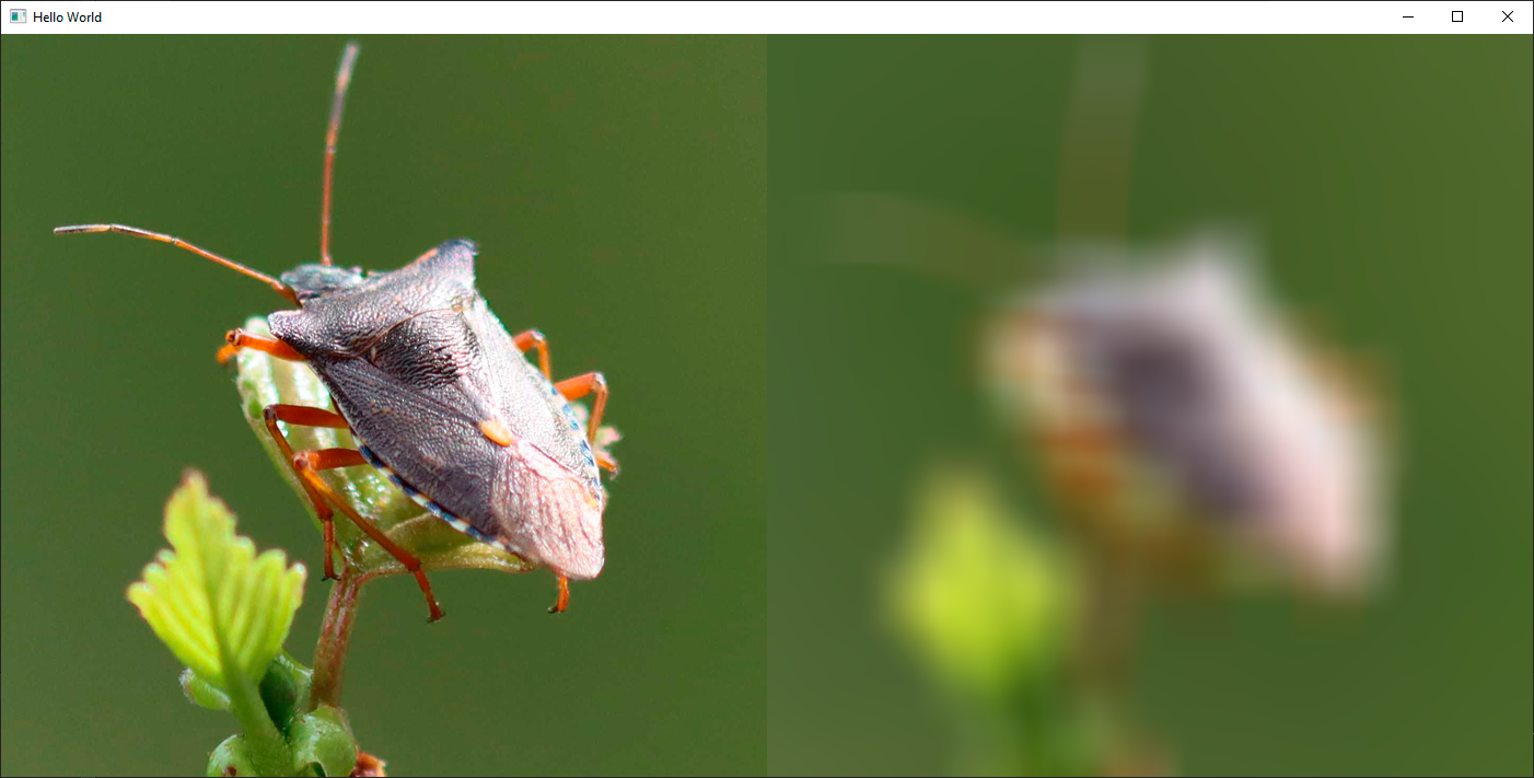
The result is blurred, but if you compare to actual optical blurring, it doesn't look quite right. The boxiness inherent in the algorithm is visible in the output as well. The reason for this is that all pixels in the kernel contribute an equal amount to the end result. In the real world, you would expect pixels closer to the output pixel to contribute more.
结果是模糊的,但如果与实际的光学模糊相比,它看起来不太正确。算法中固有的盒度在输出中也可见。其原因是内核中的所有像素对最终结果的贡献相等。在现实世界中,您会期望更接近输出像素的像素贡献更多。
Gaussian Blur
高斯模糊
This is what the Gaussian blur addresses: Instead of just doing a rough average of the pixels, the contribution of each pixel is weighted by a function of its distance to the center of the kernel. The function we use is the Gaussian function, which is a statistical function that describes normal distribution.
这就是高斯模糊解决的问题:不是简单地对像素进行粗略平均,而是根据每个像素到核中心的距离对每个像素的贡献进行加权。我们使用的函数是高斯函数,这是一个描述正态分布的统计函数。
We change our fragment shader to implement a gaussian blur:
我们更改片段着色器以实现高斯模糊:
#version 440

layout(location = 0) in vec2 textureCoord;
layout(location = 0) out vec4 fragColor;

layout(std140, binding = 0) uniform buf {
    mat4 qt_Matrix;
    float qt_Opacity;
    vec2 pixelStep;
    int radius;
    float deviation;
};
layout(binding = 1) uniform sampler2D src;

#define PI 3.1415926538

float gaussianWeight(vec2 coords)
{
    float x2 = pow(coords.x, 2.0);
    float y2 = pow(coords.y, 2.0);
    float deviation2 = pow(deviation, 2.0);

    return (1.0 / (2.0 * PI * deviation2)) * exp(-(x2 + y2) / (2.0 * deviation2));
}

void main(void)
{
    vec3 sum = vec3(0.0, 0.0, 0.0);
    float gaussianSum = 0.0;
    for (int x = -radius; x <= radius; ++x) {
        for (int y = -radius; y <= radius; ++y) {
            vec2 c = textureCoord + vec2(x, y) * pixelStep;
            float w = gaussianWeight(vec2(x, y));
            sum += texture(src, c).rgb * w;
            gaussianSum += w;
        }
    }

    fragColor = vec4(sum / gaussianSum, 1.0) * qt_Opacity;
}
We have now defined a new function in the shader which returns the Gaussian weight for a pixel which is at distance "coords" from the center of the kernel. We have also added a "deviation" uniform for extra customizability. Instead of calculating the mean of all values, we now multiply each sample with this Gaussian weight instead. Looking at the result, it's clear that the Gaussian blur gives much fewer artifacts and looks more like an optical blur.
现在,我们在着色器中定义了一个新函数,该函数返回距离内核中心“坐标”的像素的高斯权重。我们还添加了“deviation”的uniform,以实现额外的可定制性。不是计算所有值的平均值,而是将每个样本乘以该高斯权重。观察结果,很明显,高斯模糊产生的伪影要少得多,看起来更像光学模糊。

It is worth noting that calculating the Gaussian weights in the fragment shader can be quite expensive. A more efficient approach would be to precalculate the weights for our chosen kernel size and then hardcode these into either the shader or the uniform input. This is why the Gaussian blur in Qt Graphical Effects is generating the shader source code at runtime based on the input values.
值得注意的是,计算片段着色器中的高斯权重可能非常昂贵。更有效的方法是预先计算所选内核大小的权重,然后将其硬编码到着色器或uniform输入中。这就是为什么Qt图形效果中的高斯模糊在运行时基于输入值生成着色器源代码。
Replacing the contents of the gaussianWeight() function in the code with such hardcoded values would be a simple way of enhancing the code in this blog.
用这样的硬编码值替换代码中gaussianWeight()函数的内容将是增强本博客中代码的简单方法。
Colorize Effect
着色效果
One of the great benefits of creating a custom shader is that you can now simply add additional effects on top with minimal overhead. To illustrate this, we will finish off by adding a colorize filter to the Gaussian blur shader.
创建自定义着色器的最大好处之一是,您现在可以简单地在顶部添加附加效果,开销最小。为了说明这一点,我们将在高斯模糊着色器中添加着色过滤器。
To make it simple, I've copied some code from the Colorize filter in Qt Graphical Effects.
为了简单起见,我从Qt图形效果中的Colorize过滤器中复制了一些代码。
#version 440

layout(location = 0) in vec2 textureCoord;
layout(location = 0) out vec4 fragColor;

layout(std140, binding = 0) uniform buf {
    mat4 qt_Matrix;
    float qt_Opacity;
    vec2 pixelStep;
    int radius;
    float deviation;
    float hue;
    float saturation;
    float lightness;
};
layout(binding = 1) uniform sampler2D src;

#define PI 3.1415926538

float gaussianWeight(vec2 coords)
{
    float x2 = pow(coords.x, 2.0);
    float y2 = pow(coords.y, 2.0);
    float deviation2 = pow(deviation, 2.0);

    return (1.0 / (2.0 * PI * deviation2)) * exp(-(x2 + y2) / (2.0 * deviation2));
}

float RGBtoL(vec3 color)
{
    float cmin = min(color.r, min(color.g, color.b));
    float cmax = max(color.r, max(color.g, color.b));
    float l = (cmin + cmax) / 2.0;
    return l;
}

float hueToIntensity(float v1, float v2, float h)
{
    h = fract(h);
    if (h < 1.0 / 6.0)
        return v1 + (v2 - v1) * 6.0 * h;
    else if (h < 1.0 / 2.0)
        return v2;
    else if (h < 2.0 / 3.0)
        return v1 + (v2 - v1) * 6.0 * (2.0 / 3.0 - h);

    return v1;
}

vec3 HSLtoRGB(vec3 color)
{
    float h = color.x;
    float l = color.z;
    float s = color.y;

    if (s < 1.0 / 256.0)
        return vec3(l, l, l);

    float v1;
    float v2;
    if (l < 0.5)
        v2 = l * (1.0 + s);
    else
        v2 = (l + s) - (s * l);

    v1 = 2.0 * l - v2;

    float d = 1.0 / 3.0;
    float r = hueToIntensity(v1, v2, h + d);
    float g = hueToIntensity(v1, v2, h);
    float b = hueToIntensity(v1, v2, h - d);
    return vec3(r, g, b);
}


void main(void)
{
    vec3 sum = vec3(0.0, 0.0, 0.0);
    float gaussianSum = 0.0;
    for (int x = -radius; x <= radius; ++x) {
        for (int y = -radius; y <= radius; ++y) {
            vec2 c = textureCoord + vec2(x, y) * pixelStep;
            float w = gaussianWeight(vec2(x, y));
            sum += texture(src, c).rgb * w;
            gaussianSum += w;
        }
    }

    float light = RGBtoL(sum / gaussianSum);
    float c = step(0.0, lightness);
    vec3 color = HSLtoRGB(vec3(hue, saturation, mix(light, c, abs(lightness))));
    fragColor = vec4(color, 1.0) * qt_Opacity;
}
In this extension of the previous code, we have added some additional uniform parameters to the uniform buffer, specifying the destination color as hue, saturation and lightness. There's also a few extra helper functions, for converting between RGB and HSL. At the end of the main() function, the actual magic happens: Instead of just outputting the blurred RGB color directly, we extract its lightness. We then combine this with the input HSL color to produce the output.
在前面代码的扩展中,我们向uniform缓冲区添加了一些额外的uniform参数,将目标颜色指定为色调、饱和度和亮度。还有一些额外的辅助函数,用于RGB和HSL之间的转换。在main()函数的末尾,实际的魔术发生了:我们不只是直接输出模糊的RGB颜色,而是提取其亮度。然后,我们将其与输入HSL颜色组合以产生输出。
In the example project, I have also added a slider which attaches to the hue, so you can easily cycle through different colors.
在示例项目中,我还添加了一个附加到色调的滑块,因此您可以轻松地循环使用不同的颜色。

Conclusion
结论
Hopefully this blog has inspired some of you to try writing your own custom shaders. Once you get past the initial learning curve, it is actually quite efficient to prototype and play around with new effects.
希望这个博客能激励你们中的一些人尝试编写自己的自定义着色器。一旦你通过了最初的学习曲线,原型制作和使用新效果实际上是非常有效率的。
We will of course continue to provide as much convenience and assistance as we can in Qt. In the future, you can expect this to be even simpler and more approachable. But even today, it's quite possible to get whatever is in your head onto the screen with a very few lines of code.
当然,我们将继续在Qt中提供尽可能多的便利和帮助。在未来,您可以期待这更简单、更容易接近。但即使在今天,只要几行代码,就可以将你头脑中的任何东西显示在屏幕上。


 2758
2758


 被折叠的 条评论
为什么被折叠?
被折叠的 条评论
为什么被折叠?
 到【灌水乐园】发言


