


 本文详细介绍了如何构建不同类型的数字电路,包括具有1000周期的计数器、4位移位寄存器和下行计数器,以及用于序列检测的有限状态机(FSM)。通过实例展示了如何设计这些电路,包括状态转换逻辑和控制信号的生成,以及如何在FSM中实现定时器功能。此外,还探讨了如何使用独热逻辑方程来表示状态转移。
提示:文章写完后,目录可以自动生成,如何生成可参考右边的帮助文档
文章目录
前言
一、Building Larger Circuits
1.Counter with period 1000
Practice:Build a counter that counts from 0 to 999, inclusive, with a period of 1000 cycles. The reset input is synchronous, and should reset the counter to 0.
翻译:
构建一个从0到999(包括999)的计数器,周期为1000个周期。复位输入是同步的,应该将计数器复位为0。
Solution(不唯一,仅供参考):
module top_module (
    input clk,
    input reset,
    output reg [9:0] q);

    always @(posedge clk)begin
        if(reset)begin
            q<=0;
        end
        else begin
            if(q==10'd999)begin
               q<=0;
            end
            else begin
                q<=q+1;
            end
        end
    end

endmodule
Timing Diagram

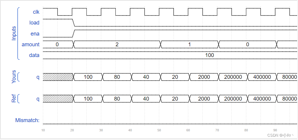
2.4-bit shift register and down counter
Practice:Build a four-bit shift register that also acts as a down counter. Data is shifted in most-significant-bit first when shift_ena is 1. The number currently in the shift register is decremented when count_ena is 1. Since the full system doesn’t ever use shift_ena and count_ena together, it does not matter what your circuit does if both control inputs are 1 (This mainly means that it doesn’t matter which case gets higher priority).
翻译:设计一个四位移位寄存器,也作为一个下行计数器。当shift_ena为1时,数据会先以最高有效位移位。当当count_ena为1时,当前在移位寄存器中的数字将递减。系统不会出现两种使能信号同时为高的情况,所以不存在优先级问题。

Solution(不唯一,仅供参考):
module top_module (
    input clk,
    input shift_ena,
    input count_ena,
    input data,
    output reg [3:0] q);
    always @(posedge clk)begin
        case({shift_ena,count_ena})
        	2'b01: q<=q-1;
            2'b10: q<={q[2:0],data};
            default :;
        endcase
    end
endmodule
Timing Diagram

3.FSM:Sequence 1101 recognizer
Practice:Build a finite-state machine that searches for the sequence 1101 in an input bit stream. When the sequence is found, it should set start_shifting to 1, forever, until reset. Getting stuck in the final state is intended to model going to other states in a bigger FSM that is not yet implemented. We will be extending this FSM in the next few exercises.
翻译:
设计一个有限状态机FSM,从输入码流中找出“1101”序列,当1101被找到后,永远的拉高start_shifting信号,直到复位才拉低。

提示:
- S0:初始状态,开始检测1101序列的第一个1,若检测到1,则跳转到S1,若检测到0,则保持该状态
- S1:若检测到1,则说明可能是1101序列的第二个1,所以状态跳转到S2, 若检测到0,则状态跳转到S0,去检测1101的第一个1
- S2:若检测到0,则说明可能是1101序列的0,所以状态跳转到S3,若检测到1,此时接收的码流为“111”,则后面的11可以视为1101序列中的前两个11,所以继续在该状态检测
- S3:若检测到1,则说明是1101序列的最后的1,所以状态跳转到S4,若检测到0,此时接收的码流为“1100”,则状态跳转到S0,重新开始检测
- S4: 保持在该状态,且在该状态拉高start_shifting信号
Solution(不唯一,仅供参考):
module top_module (
    input clk,
    input reset,      // Synchronous reset
    input data,
    output reg start_shifting);
	parameter	S0=5'b00001,
    			S1=5'b00010,
    			S2=5'b00100,
    			S3=5'b01000,
    			S4=5'b10000;
    reg [4:0] cur_state,next_state;

    always @(posedge clk)begin
        if(reset)begin
        	cur_state<=S0;
        end
        else begin
            cur_state<=next_state;
        end
    end

    always @(*)begin
        if(reset)begin
           next_state<=S0;
        end
        else begin
            case(cur_state)
                S0: next_state=data?S1:S0;
                S1: next_state=data?S2:S0;
                S2: next_state=data?S2:S3;
                S3: next_state=data?S4:S0;
                S4: next_state=S4;
                default : next_state=S0;
            endcase
        end
    end

    always @(posedge clk)begin
        if(reset)begin
        	start_shifting<=0;
        end
        else begin
            case(next_state)
                S0,S1,S2,S3:
                    start_shifting<=0;
                S4: start_shifting<=1;
                default:start_shifting<=0;
            endcase
        end
    end
endmodule
Timing Diagram

4.FSM:Enable shift register
Practice:As part of the FSM for controlling the shift register, we want the ability to enable the shift register for exactly 4 clock cycles whenever the proper bit pattern is detected. We handle sequence detection in Exams/review2015_fsmseq, so this portion of the FSM only handles enabling the shift register for 4 cycles.
Whenever the FSM is reset, assert shift_ena for 4 cycles, then 0 forever (until reset).
翻译:作为控制移位寄存器的FSM的一部分,我们希望当检测到适当的位模式时,能够在恰好4个时钟周期内启用移位寄存器。我们在Exams/review2015_fsmseq中处理序列检测,因此FSM的这部分只处理启用移位寄存器4个周期。
每当FSM被重置时,断言shift_ena 4个周期,然后永远为0(直到重置)。
 .提示:这道题的意思是,如果复位信号有效,shift_ena信号就为1;当复位信号撤销以后,shift_ena信号保持4个周期高电平后变为0。
Solution(不唯一,仅供参考):
module top_module (
    input clk,
    input reset,      // Synchronous reset
    output reg shift_ena);
    reg [2:0] cnt;

    always @(posedge clk)begin
        if(reset)begin
            shift_ena<=1;
        end
        else if(cnt==3) begin
           shift_ena<=0;
        end
        else begin
            shift_ena<=shift_ena;
        end
    end
    //计数0-3
    always @(posedge clk)begin
        if(reset)begin
           cnt<=0;
        end
        else if(shift_ena)begin
                cnt<=cnt+1;
            end
            else begin
               cnt<=cnt;
            end
    end

endmodule
5.FSM:The complete FSM
Practice:We want to create a timer that:
- is started when a particular pattern (1101) is detected,
- shifts in 4 more bits to determine the duration to delay,
- waits for the counters to finish counting, and
- notifies the user and waits for the user to acknowledge the timer.
翻译: 简单来说, 首先检测序列“1101”,检测到后停止检测,拉高shift_ena4个时钟周期,然后拉高counting直到输入done_counting为1,然后拉高done直到输入ack为1。
提示:
-
S:初始状态,开始检测1101序列的第一个1,若检测到1,则跳转到S1,若检测到0,则保持该状态
-
S1:若检测到1,则说明可能是1101序列的第二个1,所以状态跳转到S11, 若检测到0,则状态跳转到S,去检测1101的第一个1
-
S11:若检测到0,则说明可能是1101序列的0,所以状态跳转到S110, 若检测到1,则保持在该状态
-
S110:若检测到1,则说明是1101序列的最后一个1,所以状态跳转到B0, 若检测到0,则状态跳转到S,去检测1101的第一个1
-
B0:直接跳转到B1
-
B1:直接跳转到B2
-
B2:直接跳转到B3
-
B3:直接跳转到COUNT
-
COUNT:当counting为1时跳转到状态WAIT,不然一直停留在该状态
-
WAIT:当ack为0时跳转到状态S,不然一直停留在该状态
Solution(不唯一,仅供参考):
module top_module (
    input clk,
    input reset,      // Synchronous reset
    input data,
    output reg shift_ena,
    output reg counting,
    input done_counting,
    output reg done,
    input ack );

    parameter	S		=4'd0,
    			S1		=4'd1,
    			S11		=4'd2,
    			S110	=4'd3,
    			B0		=4'd4,
    			B1		=4'd5,
    			B2		=4'd6,
    			B3		=4'd7,
    			COUNT	=4'd8,
    			WAIT	=4'd9;

    reg [3:0]	cur_state,next_state;
    always @(posedge clk)begin
        if(reset)begin
           cur_state<=S;
        end
        else begin
            cur_state<=next_state;
        end
    end

    always @(*)begin
        if(reset)begin
           next_state=S;
        end
        else begin
            case(cur_state)
                S:		next_state=data?S1:S;
                S1:		next_state=data?S11:S;
                S11:	next_state=data?S11:S110;
                S110: 	next_state=data?B0:S;
                B0:		next_state=B1;
                B1:		next_state=B2;
                B2:		next_state=B3;
                B3:		next_state=COUNT;
                COUNT:
                    if(done_counting)
                        next_state=WAIT;
                	else
                        next_state=COUNT;
                WAIT:
                    if(ack)
                        next_state=S;
                	else
                        next_state=WAIT;
                default : next_state=S;
            endcase
        end
    end

    always @(posedge clk)begin
        if(reset)begin
            shift_ena<=0;
            counting<=0;
            done<=0;
        end
        else begin
            case(next_state)
                B0,B1,B2,B3:begin
                   shift_ena<=1;
                    counting<=0;
                    done<=0;
                end
                COUNT:begin
                    shift_ena<=0;
                    counting<=1;
                    done<=0;
                end
                WAIT:begin
                    shift_ena<=0;
                    counting<=0;
                    done<=1;
                end
                default:begin
                    shift_ena<=0;
                    counting<=0;
                    done<=0;
                end
            endcase
        end
    end
endmodule
6.The complete timer
Practice:See Lfsr5 for explanations.Build a 32-bit Galois LFSR with taps at bit positions 32, 22, 2, and 1.
翻译: 在数据流中检测到序列 1101 后,电路需要将接下来的 4bit 数据移入移位寄存器。4bit 数据决定了计数器的计数周期,称为 delay[3:0]。首先到达的比特作为数据的高位。之后,状态机置高 counting 信号,表示其正在等待计数器完成计数。在 FSM 中增加计数器状态,计数周期为 (delay[3:0] + 1 )* 1000 个时钟周期。比如 delay = 0 时,计数值为 1000 个周期。delay = 5 代表 6000 个周期。同时输出 count 当前剩余的计数周期,输出当前剩余计数周期的千位(比如,还剩1000个周期输出 1,还剩 999 个周期时输出 0)。当计数停止后,count 的输出可以为任意数。
当计数完成后,电路置高 done 信号通知上层应用计数器计数完成,等待 ack 信号置高后,状态机清除 done 信号,返回空闲状态等待捕获下一个 1101 序列。
本题给出了一个期望输入输出的例子。图中的斜线代表当前信号为 ‘X’, 表示状态机不关心该信号当前的值。比如图例中,一旦 FSM 检测到 1101 序列并读取 delay[3:0] 后,在此次计数器事件完成前,对于当前的数据流不再关心。
在图例中,电路计数周期为 2000 ,因为 delay[3:0] 数值为 4’b0001 。在后续的第二个计数周期中,因为 delay[3:0] = 4‘b1110,所以计数周期为 15000。
提示:
- S : 初始状态,检测到1,则跳转到S1,否则保持该状态
- S1 : 检测到1,则跳转到S11,否则跳转到S
- S11 : 检测到0,则跳转到S110,否则保持该状态
- S110 : 检测到1,则跳转到DELAY ,否则跳转到S
- DELAY : 在次状态延时4个时钟周期(cnt_delay从0-3),用来接收输入码流上接下来的4个数据,作为延时的时间
- COUNT : 延时状态,直到延时到指定的时间
- WAIT : 在次状态等待akc响应信号
Solution(不唯一,仅供参考):
module top_module (
    input clk,
    input reset,      // Synchronous reset
    input data,
    output [3:0] count,
    output counting,
    output done,
    input ack );

    parameter		S=4'd0,
    				S1=4'd1,
    				S11=4'd2,
    				S110=4'd3,
    				DELAY=4'd4,
    				COUNT=4'd5,
    				WAIT=4'd6;
    reg[3:0] 		cur_state,next_state;
    reg[1:0]		cnt_delay;
    reg[15:0]		cnt;
    reg[3:0]		delay;

    always @(posedge clk)begin
        if(reset)
            cur_state <= S;
        else
            cur_state <= next_state;
	end

    always @(*)begin
        if(reset)begin
           next_state=S;
        end
        else begin
            case(cur_state)
                S:		next_state=data?S1:S;
                S1:		next_state=data?S11:S;
                S11:	next_state=data?S11:S110;
                S110:	next_state=data?DELAY:S;
                DELAY:
                    if(cnt_delay==2'd3)
                        next_state=COUNT;
                	else
                        next_state=WAIT;
                COUNT:
                    if(cnt==16'd0)
                        next_state=WAIT;
                	else
                        next_state=DELAY;
                WAIT:
                    if(ack)
                        next_state=S;
                	else
                        next_state=WAIT;
                default: next_state=S;
            endcase
        end
    end
    //第三段,描述输出
    assign count=cnt/1000;
    assign counting =(cur_state==COUNT);
    assign done=(cur_state==WAIT);
    //延时计数器,计数4个时钟,来接收delay数据
    always @(posedge clk)begin
        if(reset)begin
        	cnt_delay<=0;
        end
        else if(cur_state==DELAY) begin
            cnt_delay<=cnt_delay+1;
        end
        else begin
           cnt_delay<=cnt_delay;
        end
    end
    //根据接收到的delay数据进行计数延时
    always @(posedge clk)begin
        if(reset)begin
           cnt<=0;
        end
        else if(cur_state==DELAY)begin
            cnt<=(delay+1)*1000-1;
        end
        else if(cur_state==COUNT)begin
            cnt<=cnt-1;
        end
        else begin
            cnt<=cnt;
        end
    end
    //接收delay数据
    always @(*)begin
        if(cur_state==DELAY)begin
            case(cnt_delay)
                2'd0:	delay[3]=data;
                2'd1:	delay[2]=data;
                2'd2:	delay[1]=data;
                2'd3:	delay[0]=data;
                default:;
            endcase
        end
        else begin
           delay=4'b0000;
        end
endmodule
7.FSM:One-hot logic equations
Practice:Write code that generates the following equations:
- B3_next – next-state logic for state B1
- S_next
- S1_next
- Count_next
- Wait_next
- done – output logic
- counting
- shift_ena
翻译:本题给出了一个具有 3 输入,3 输出以及 10 个状态的 FSM 的状态转移图。仅需要实现状态转移和输出逻辑的组合逻辑,tb 会检测是否按照要求使用了独热码。

Solution(不唯一,仅供参考):
直接用独热码进行输出即可
module top_module(
    input d,
    input done_counting,
    input ack,
    input [9:0] state,    // 10-bit one-hot current state
    output B3_next,
    output S_next,
    output S1_next,
    output Count_next,
    output Wait_next,
    output done,
    output counting,
    output shift_ena
); //

    // You may use these parameters to access state bits using e.g., state[B2] instead of state[6].
    parameter S=0, S1=1, S11=2, S110=3, B0=4, B1=5, B2=6, B3=7, Count=8, Wait=9;

	assign B3_next = state[B2];
    assign S_next = ~d & state[S] | ~d & state[S1] | ~d & state[S110] | ack & state[Wait];
    assign S1_next = d & state[S];
    assign Count_next = state[B3] | ~done_counting & state[Count];
    assign Wait_next = done_counting & state[Count] | ~ack & state[Wait];
    assign done = state[Wait];
    assign counting = state[Count];
    assign shift_ena = state[B0] | state[B1] | state[B2] |state[B3];

endmodule
继续加油!!!!!
继续加油!!!!!
继续加油!!!!!
继续加油!!!!!


 861
861

 被折叠的 条评论
为什么被折叠?
被折叠的 条评论
为什么被折叠?
 到【灌水乐园】发言


