


【HDLBits】Circuits_Sequential Logic_Building Larger Cirsuits
- I Counter with period 1000 (Exams/review2015 count1k)
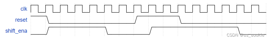
- II 4-bit shift register and down counter (Exams/review2015 shiftcount)
- III FSM:Sequence 1101 recognizer (Exams/review2015 fsmseq)
- IV FSM: Enable shift register (Exams/review2015 fsmshift)
- V FSM: the complete FSM (Exams/review2015 fsm)
- VI the complete timer
- VII FSM: One-hot logic equations (Exams/review2015 fsmonehot)
I Counter with period 1000 (Exams/review2015 count1k)
1.代码编写
module top_module (
    input clk,
    input reset,
    output [9:0] q);
    always@(posedge clk) begin
        if(reset)
            q <= 10'd0;
        else
            q <= (q == 10'd999)? 10'd0:q+10'd1;
    end
endmodule
2.提交结果
Success
3.题目分析
Build a counter that counts from 0 to 999, inclusive, with a period of 1000 cycles. The reset input is synchronous, and should reset the counter to 0.
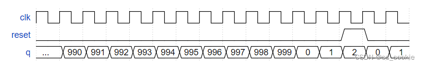
注意,最后是卡999(0至999的1000个)而非1000(0至1000有1001个)。
II 4-bit shift register and down counter (Exams/review2015 shiftcount)
1.代码编写
module top_module (
    input clk,
    input shift_ena,
    input count_ena,
    input data,
    output [3:0] q);
    always@(posedge clk) begin
        if(shift_ena)
            q <= {q[2:0],data};
        else if(count_ena)
            q <= q - 4'd1;
        else
            q <= q;
    end
endmodule
2.提交结果
Success
3.题目分析
This is the first component in a series of five exercises that builds a complex counter out of several smaller circuits. See the final exercise for the overall design.
Build a four-bit shift register that also acts as a down counter. Data is shifted in most-significant-bit first when shift_ena is 1. The number currently in the shift register is decremented when count_ena is 1. Since the full system doesn’t ever use shift_ena and count_ena together, it does not matter what your circuit does if both control inputs are 1 (This mainly means that it doesn’t matter which case gets higher priority).
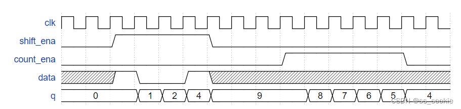
这是一个大系统的第一部分,计数部分。当shift_ena=1,开始写入数据,最先写入的时最高位;当count_ena=1,开始向下递减。
输入信号中不存在shift_ena与count_ena同时为1的情况,所以无需考虑两个使能信号的优先级;又由波形可知,当两个使能信号都为0,q保持。
III FSM:Sequence 1101 recognizer (Exams/review2015 fsmseq)
1.代码编写
module top_module (
    input clk,
    input reset,      // Synchronous reset
    input data,
    output start_shifting);
    reg [2:0] state,next_state;
    parameter [2:0] IDLE = 3'd0,S1 = 3'd1,S2 = 3'd2,S3 = 3'd3,S4 = 3'd4;
    // state transfer
    always@(*) begin
        case(state)
            IDLE: begin
                next_state = (data)? S1:IDLE;
            end
            S1: begin
                next_state = (data)? S2:IDLE;
            end
            S2: begin
                next_state = (data)? S2:S3;
            end
            S3: begin
                next_state = (data)? S4:IDLE;
            end
            S4: begin
                next_state = S4;
            end
        endcase
    end
    // flip-flop
    always@(posedge clk) begin
        if(reset)
            state <= IDLE;
        else
            state <= next_state;
    end
    //output
    assign start_shifting = (state == S4);
endmodule
2.提交结果
Success
3.题目分析
This is the second component in a series of five exercises that builds a complex counter out of several smaller circuits. See the final exercise for the overall design.
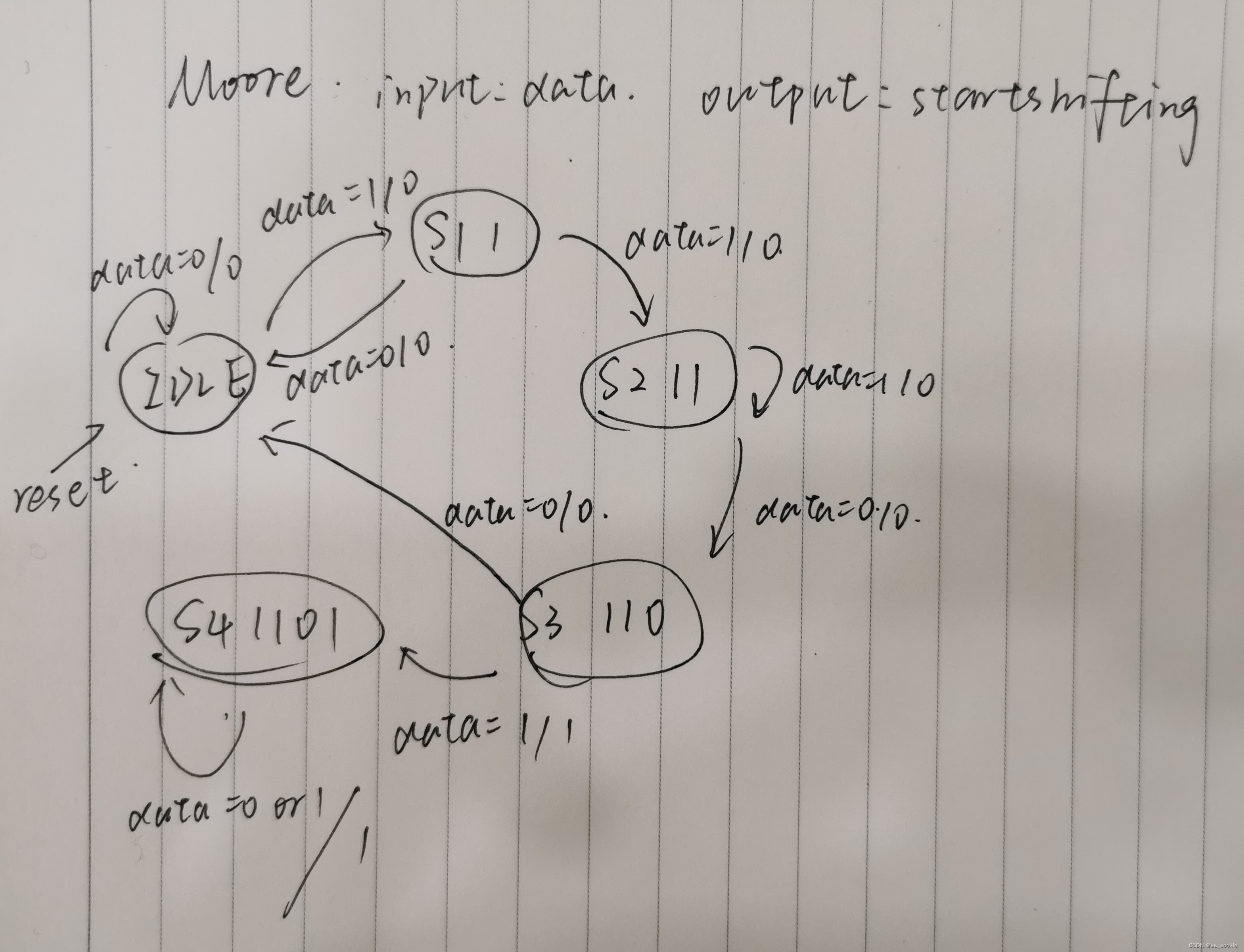
Build a finite-state machine that searches for the sequence 1101 in an input bit stream. When the sequence is found, it should set start_shifting to 1, forever, until reset. Getting stuck in the final state is intended to model going to other states in a bigger FSM that is not yet implemented. We will be extending this FSM in the next few exercises.
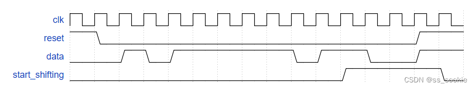
做出状态转移图如下(Moore型):
IV FSM: Enable shift register (Exams/review2015 fsmshift)
1.代码编写
module top_module (
    input clk,
    input reset,      // Synchronous reset reset相当于上一题输出的start_shifting
    output shift_ena);
    reg [2:0] cnt;
    always@(posedge clk) begin
        if(reset) // reset一次,cnt置零
            cnt <= 3'd0;
        else if(cnt == 3'd6) // reset=0,且已完成4cycle输出的情况
            cnt <= 3'd6;
        else if(cnt == 3'd4) // reset=0,且刚完成了4周期的输出
            cnt <= 3'd6;
        else if(cnt < 3'd4) // reset=0,但未完成4cycle输出的情况
            cnt <= cnt+3'd1;
    end
    assign shift_ena = (cnt < 3'd4)? 1'b1:1'b0;
endmodule
2.提交结果
Success
3.题目分析
This is the third component in a series of five exercises that builds a complex counter out of several smaller circuits. See the final exercise for the overall design.
As part of the FSM for controlling the shift register, we want the ability to enable the shift register for exactly 4 clock cycles whenever the proper bit pattern is detected. We handle sequence detection in Exams/review2015_fsmseq, so this portion of the FSM only handles enabling the shift register for 4 cycles.
Whenever the FSM is reset, assert shift_ena for 4 cycles, then 0 forever (until reset).
只需要在reset=1时产生4cycle的shift_ena=1即可,当reset连续等于1,这个输出是可以周期重叠的。
(reset在n个cycle=1,则shift_ena在(n-1)+4个cycle为1,而非4*n个)。
V FSM: the complete FSM (Exams/review2015 fsm)
1.代码编写
module top_module (
    input clk,
    input reset,      // Synchronous reset
    input data,
    output shift_ena,
    output counting,
    input done_counting,
    output done,
    input ack );
    reg [3:0] state,next_state;
    parameter [3:0] S = 4'd0,S1 = 4'd1,S11 = 4'd2,S110 = 4'd3,B0 = 4'd4,B1 = 4'd5,B2 = 4'd6,B3 = 4'd7,Count = 4'd8,Wait = 4'd9;
    // state transfer
    always@(*) begin
        case(state)
            S: begin
                next_state = (data)? S1:S;
            end
            S1: begin
                next_state = (data)? S11:S;
            end
            S11: begin
                next_state = (data)? S11:S110;
            end
            S110: begin
                next_state = (data)? B0:S;
            end
            B0: begin
                next_state = B1;
            end
            B1: begin
                next_state = B2;
            end
            B2: begin
                next_state = B3;
            end
            B3: begin
                next_state = Count;
            end
            Count: begin
                next_state =(done_counting)? Wait:Count;
            end
            Wait: begin
                next_state =(ack)? S:Wait;
            end
        endcase
    end
    // flip-flop
    always@(posedge clk) begin
        if(reset)
            state <= S;
        else
            state <= next_state;
    end
    // output
    assign shift_ena = (state == B0 || state == B1 || state == B2 || state == B3)? 1'b1:1'b0;
    assign counting = (state == Count)? 1'b1:1'b0;
    assign done = (state == Wait)? 1'b1:1'b0;

endmodule
2.提交结果
Success
3.题目分析
This is the fourth component in a series of five exercises that builds a complex counter out of several smaller circuits. See the final exercise for the overall design.
You may wish to do FSM: Enable shift register and FSM: Sequence recognizer first.
We want to create a timer that:
- is started when a particular pattern (1101) is detected,
- shifts in 4 more bits to determine the duration to delay,
- waits for the counters to finish counting, and
- notifies the user and waits for the user to acknowledge the timer.
In this problem, implement just the finite-state machine that controls the timer. The data path (counters and some comparators) are not included here.
The serial data is available on the data input pin. When the pattern 1101 is received, the state machine must then assert output shift_ena for exactly 4 clock cycles.
After that, the state machine asserts its counting output to indicate it is waiting for the counters, and waits until input done_counting is high.
At that point, the state machine must assert done to notify the user the timer has timed out, and waits until input ack is 1 before being reset to look for the next occurrence of the start sequence (1101).
The state machine should reset into a state where it begins searching for the input sequence 1101.
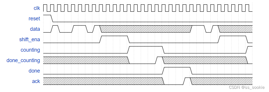
Here is an example of the expected inputs and outputs. The ‘x’ states may be slightly confusing to read. They indicate that the FSM should not care about that particular input signal in that cycle. For example, once a 1101 pattern is detected, the FSM no longer looks at the data input until it resumes searching after everything else is done.
题目给的状态转移图:
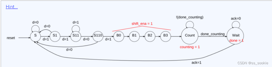
我做的状态转移图:
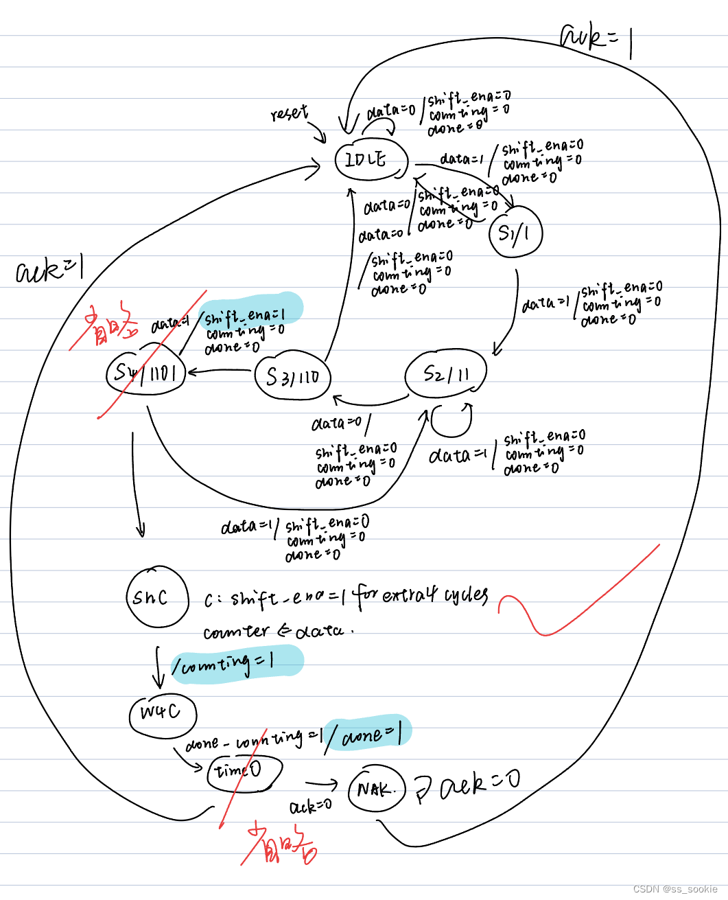
多了状态 S4/1101,与状态timeO(表示计时结束,在监测ACK之前)。
VI the complete timer
1.代码编写
module top_module (
    input clk,
    input reset,      // Synchronous reset
    input data,
    output [3:0] count,
    output counting,
    output done,
    input ack );
    reg [9:0] counter;
    reg clkn;
    reg [4:0] delay; // 防 count=4'b1111(4'hf)时,delay=count+4'd1=0溢出。
    reg [3:0] state,next_state;
    parameter [3:0] S = 4'd0,S1 = 4'd1,S11 = 4'd2,S110 = 4'd3,B0 = 4'd4,B1 = 4'd5,B2 = 4'd6,B3 = 4'd7,Count2 = 4'd8,Wait = 4'd9;
    // state transfer
    always@(*) begin
        case(state)
            S: begin
                next_state = (data)? S1:S;
            end
            S1: begin
                next_state = (data)? S11:S;
            end
            S11: begin
                next_state = (data)? S11:S110;
            end
            S110: begin
                next_state = (data)? B0:S;
            end
            B0: begin
                next_state = B1;
            end
            B1: begin
                next_state = B2;
            end
            B2: begin
                next_state = B3;
            end
            B3: begin
                next_state = Count2;
            end
            Count2: begin
                next_state =(delay == 5'd0)? Wait:Count2;
            end
            Wait: begin
                next_state =(ack)? S:Wait;
            end
            default: next_state = S;
        endcase
    end
    // flip-flop
    always@(posedge clk) begin
        if(reset)
            state <= S;
        else
            state <= next_state;
    end
    // output
    always@(posedge clk) begin
        counting <= (next_state == Count2 && !reset)? 1'b1:1'b0; // 这里记得加条件!reset,否则倒数中途reset需要再多隔1cycle,(先变state再变counting)
        done <= (next_state == Wait)? 1'b1:1'b0;
    end

    // shift reg
    always@(posedge clk) begin
        if(state == B0 || state == B1 || state == B2) begin
            count <= {count[2:0],data};
            delay <= {delay[3:0],data};
            counter <= 10'd0;
        end
        else if(state == B3) begin
            count <= {count[2:0],data};
            delay <= {delay[3:0],data} + 4'd1;
            counter <= 10'd0;
        end
        else if(next_state == Count2) begin
            count <= (count != 4'd0 && counter == 10'd999)? count - 4'd1:count; // 后者亦满足当count=0则其一直保持0,只是输出的形式,真的倒数看delay
            if(delay != 4'd1 && counter == 10'd999) begin //非1的时候,在每一个0进行减
                delay <= delay - 5'd1;
            end
            else if(delay == 5'd1 && counter == 10'd998) begin
                delay <= 5'd0;
            end
            else begin
                delay <= delay;
            end
            counter <= (counter == 10'd999)? 10'd0:counter+10'd1; // frequency divider
        end
        else begin
            counter <= 10'd0;
            count <= 4'd0; // 其他state,count保持0
            delay <= 5'd0;
        end
    end


endmodule
2.提交结果
Success
3.题目分析
This is the fifth component in a series of five exercises that builds a complex counter out of several smaller circuits. You may wish to do the four previous exercises first (counter, sequence recognizer FSM, FSM delay, and combined FSM).
We want to create a timer with one input that:
- is started when a particular input pattern (1101) is detected,
- shifts in 4 more bits to determine the duration to delay,
- waits for the counters to finish counting, and
- notifies the user and waits for the user to acknowledge the timer.
The serial data is available on the data input pin. When the pattern 1101 is received, the circuit must then shift in the next 4 bits, most-significant-bit first. These 4 bits determine the duration of the timer delay. I’ll refer to this as the delay[3:0].
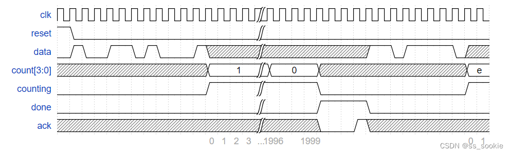
After that, the state machine asserts its counting output to indicate it is counting. The state machine must count for exactly (delay[3:0] + 1) * 1000 clock cycles. e.g., delay=0 means count 1000 cycles, and delay=5 means count 6000 cycles. Also output the current remaining time. This should be equal to delay for 1000 cycles, then delay-1 for 1000 cycles, and so on until it is 0 for 1000 cycles. When the circuit isn’t counting, the count[3:0] output is don’t-care (whatever value is convenient for you to implement).
At that point, the circuit must assert done to notify the user the timer has timed out, and waits until input ack is 1 before being reset to look for the next occurrence of the start sequence (1101).
The circuit should reset into a state where it begins searching for the input sequence 1101.
Here is an example of the expected inputs and outputs. The ‘x’ states may be slightly confusing to read. They indicate that the FSM should not care about that particular input signal in that cycle. For example, once the 1101 and delay[3:0] have been read, the circuit no longer looks at the data input until it resumes searching after everything else is done. In this example, the circuit counts for 2000 clock cycles because the delay[3:0] value was 4’b0001. The last few cycles starts another count with delay[3:0] = 4’b1110, which will count for 15000 cycles.
注意几个问题:
没有直接对count进行减:若直接对count进行减,没有找到一个方法可以在不对count进行*1000或+1的基础上实现向下计数器的好方法。
count是4bits,delay是5bits:当count=4’b1111(4‘hf)时,防止delay=count+1=4’b0000溢出,设delay比count多1bit位。
需要在reset时,特别置counting=0:应对state=Count2中途reset的情况。(否则会有1cycle延迟,reset先影响state,state再影响counting)
对delay=1时的倒数进行了特殊处理:否则倒数结束后会多延迟1cycle的状态,进而多延迟1cycle的counting与done值。
VII FSM: One-hot logic equations (Exams/review2015 fsmonehot)
1.代码编写
module top_module(
    input d,
    input done_counting,
    input ack,
    input [9:0] state,    // 10-bit one-hot current state 这个是独热码输入现态
    output B3_next,
    output S_next,
    output S1_next,
    output Count_next,
    output Wait_next,
    output done,
    output counting,
    output shift_ena
); //

    // You may use these parameters to access state bits using e.g., state[B2] instead of state[6].
    parameter S=0, S1=1, S11=2, S110=3, B0=4, B1=5, B2=6, B3=7, Count=8, Wait=9; // 表示独热码等于1的位

    // assign B3_next = ...;
    // assign S_next = ...;
    // etc.
    assign B3_next = state[B2]; // 到达B3(B3的次态逻辑/用次态逻辑表示到达B3状态)
    assign S_next = state[S]&&!d || state[S1]&&!d || state[S110]&&!d || state[Wait]&&ack ;
    assign S1_next = state[S]&&d;
    assign Count_next = state[Count]&&!done_counting || state[B3];
    assign Wait_next = state[Wait]&&!ack || state[Count]&&done_counting;
    assign done = state[Wait];
    assign counting = state[Count];
    assign shift_ena = state[B0] || state[B1] || state[B2] || state[B3];

endmodule
2.提交结果
Success
3.题目分析
Given the following state machine with 3 inputs, 3 outputs, and 10 states:
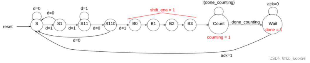
Derive next-state logic equations and output logic equations by inspection assuming the following one-hot encoding is used: (S, S1, S11, S110, B0, B1, B2, B3, Count, Wait) = (10’b0000000001, 10’b0000000010, 10’b0000000100, … , 10’b1000000000)
Derive state transition and output logic equations by inspection assuming a one-hot encoding. Implement only the state transition logic and output logic (the combinational logic portion) for this state machine. (The testbench will test with non-one hot inputs to make sure you’re not trying to do something more complicated. See fsm3onehot for a description of what is meant by deriving logic equations “by inspection” for one-hot state machines.)
Write code that generates the following equations:
- B3_next – next-state logic for state B3
- S_next
- S1_next
- Count_next
- Wait_next
- done – output logic
- counting
- shift_ena
我一开始是真没看懂这道题,看这些输出:
 assign B3_next = state[B2]; // 到达B3(B3的次态逻辑/用次态逻辑表示到达B3状态)
    assign S_next = state[S]&&!d || state[S1]&&!d || state[S110]&&!d || state[Wait]&&ack ;
    assign S1_next = state[S]&&d;
    assign Count_next = state[Count]&&!done_counting || state[B3];
    assign Wait_next = state[Wait]&&!ack || state[Count]&&done_counting;
    assign done = state[Wait];
    assign counting = state[Count];
    assign shift_ena = state[B0] || state[B1] || state[B2] || state[B3];
“done,counting,shift_ena”做输出,有“处于Wait状态,处于Count状态,处于shift_ena状态”之意。
加上需要的输出都是一位的逻辑值,所以,猜测xx_next表示:次态是否为xx?
S1_next = is next_state S1?


 254
254


 被折叠的 条评论
为什么被折叠?
被折叠的 条评论
为什么被折叠?
 到【灌水乐园】发言


