


这次好好的梳理一下。
先从两种旋转开始说起。
**参考:https://blog.51cto.com/xxpcb/2903395**
1、坐标轴不动,向量绕原点旋转后的关系
旋转前坐标为(x,y,z),旋转后为(x',y',z')。
旋转情况为:
绕z轴旋转yaw,绕y轴旋转pitch,绕x轴旋转roll。
这里明显可知道,每次都是绕的是固定的原坐标系轴,即可以说是外旋。这个也是这里可以统一概念的地方。
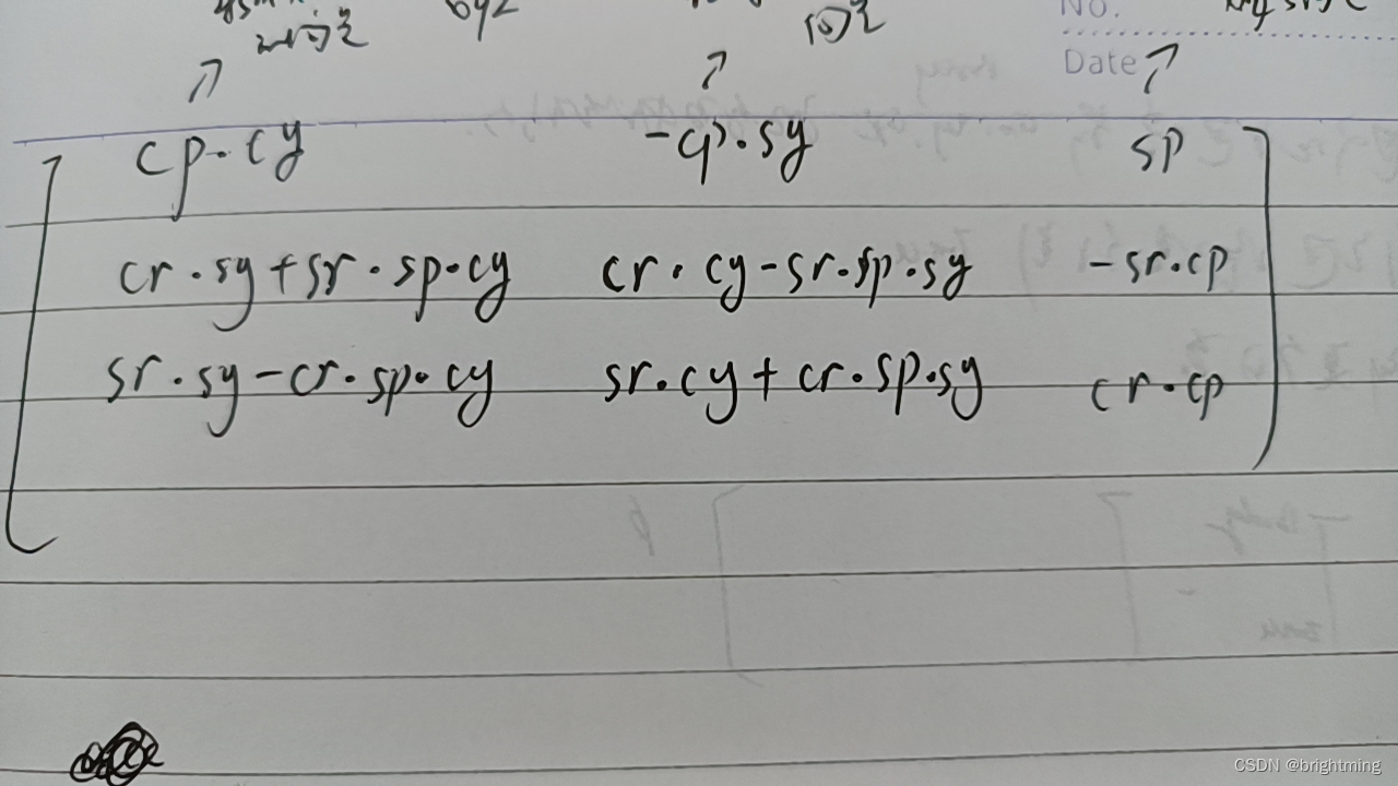
那么旋转矩阵为:
绕z轴旋转后的情况是:
在这个基础上,绕y轴旋转:
在这个基础上,绕x轴旋转:
把矩阵乘起来,就得到完整的矩阵。从等式可以看出来,是Rot_old_to_new的。
2、坐标轴旋转,原来的向量在新的坐标系下的表示
这个本质上,要计算出新的坐标轴的基向量在原坐标轴的表示。
在上一步已经知道了向量的旋转前后的表示关系。如果把这个向量变成坐标轴,再根据以上变化矩阵计算出新的坐标轴的位置,放在转换矩阵中,可以得到rot_new_to_old。没错是,new_to_old,因为是把新的坐标轴的基向量在原坐标系下的值放进去的。
还是按照z->y->x的旋转顺序,可以一次得到(1,0,0),(0,1,0),(0,0,1)旋转后分别是:
===》新的x坐标轴在原坐标系的表示
===》新的y坐标轴在原坐标系的表示
===》新的z坐标轴在原坐标系的表示。
构建一个Rot3x3矩阵,把这三列,放进去,就得到了Rot_new_to_old矩阵:
回到标题的问题,坐标轴旋转后,原来的向量是在新的坐标系怎么表示呢?
就是这样了,取个逆,得到Rot_old_to_new,再乘上原来的向量,就得到了在新坐标系下的表示。
3、利用这些信息来计算静止状态下的imu的roll、pitch角度
目标是求出,imu的坐标系,相对于Enu坐标系的转换,即Rot_body_to_enu。
已知道在imu下测量到的重力情况为:grav_body=[acc_x,acc_y,acc_z],这个在body坐标系下;
在Enu坐标系下,grav_enu重力的情况为:[0,0,-g] (重力方向向下,enu的z轴向上)。
按照上面的说法,R_new_to_old,可以直接获取,利用关系计算:
grav_enu=R_new_to_old*grav_body
得到:
0=gx=cp*cy*ax-cp*sy*ay+sp*az
0=(cr*sy+sr*sp*cy)*ax+(cr*cy-sr*sp*sy)*ay+sr*cp*az
-g=(sr*sy-cr*sp*cy)*ax+(sr*cy+cr*sp*sy)*ay+cr*cp*az
这个不是很好算。
转换一下思路:
以grav_body为开始坐标,计算grav_enu相对于它的旋转情况,那就比较简单:
grav_body(当做是old) = R_new_to_old * grav_enu(当做是new)
算出这个R_new_to_old后,求个逆,就得到了 grav_body->grav_enu的变化。
因为grav_enu 中的x\y都是0,所以可以得:
ax=sp*gz
ay=-sr*cp*gz
az=cr*cp*gz
那么:pitch=asin(ax/gz) roll=-atan(ay/az)
将角度带入那个R_new_to_old(这里的new、old都是相对来说的,哪个都可以作为new和old),就可以得到这个rot矩阵。此时的含义是env_to_body。
求逆以后,得到body_to_env,再获里面的roll、pitch,就是body相对于enu旋转的角度。
(会不会太绕了,起码思路清晰连贯了)
Eigen::Matrix3d calc_rot_body_to_enu(Eigen::Vector3d grav_in_old,Eigen::Vector3d grav_in_body){

    Eigen::Vector3d acc_mea_in_body=grav_in_body;
    // std::cout<<"grav_in_old = "<<grav_in_old.transpose()<<",acc_mea_in_body = "<<acc_mea_in_body.transpose()
    // <<std::endl;

    //反向计算出角度
    //为了计算方便,以acc_mea_in_body所在的body为起点,计算到old坐标系的roll,pitch,yaw,计算出T,然后求逆,得到的矩阵应该等价于rot_old_to_new
    double roll_enu_to_body=-atan(acc_mea_in_body(1)/acc_mea_in_body(2));
    double pitch_enu_to_body=asin(acc_mea_in_body(0)/grav_in_old(2));
    double yaw_enu_to_body=0;
    Eigen::Matrix3d R_enu_to_body;
    double cp=cos(pitch_enu_to_body);
    double sp=sin(pitch_enu_to_body);
    double cy=cos(yaw_enu_to_body);
    double sy=sin(yaw_enu_to_body);
    double cr=cos(roll_enu_to_body);
    double sr=sin(roll_enu_to_body);

    R_enu_to_body<<cp*cy,           -cp*sy,         sp,
                    cr*sy+sr*sp*cy,cr*cy-sr*sp*sy,-sr*cp,
                    sr*sy-cr*sp*cy,sr*cy+cr*sp*sy,cr*cp;
    Eigen::Matrix3d R_body_to_enu=R_enu_to_body.inverse();

    return R_body_to_enu;
}

void test_calc_vector_matrix(){
    float roll=-10.0/180*M_PI;
    float pitch=60.0/180*M_PI;
    float yaw=0.0/180*M_PI;
    std::cout<<"init yaw="<<yaw * (180 / M_PI)<<",pitch="<<pitch* (180 / M_PI)<<",roll="<<roll* (180 / M_PI)<<std::endl;


    //利用单个旋转构造
    Eigen::Matrix3d rot_x,rot_y,rot_z;
    rot_x<<1,0,0,
            0,cos(roll),-sin(roll),
            0,sin(roll),cos(roll);

    rot_y<<cos(pitch),0,sin(pitch),
            0,1,0,
            -sin(pitch),0,cos(pitch);

    rot_z<<cos(yaw),-sin(yaw),0,
          sin(yaw),cos(yaw),0,
          0,0,1;

    //得到的rot是新的坐标轴到旧坐标轴的转换。
    //以向量旋转的角度来看,相当于是得到的了新的坐标轴的x\y\z轴在老坐标轴的表示
    //即T_new_to_old,用这个,就可以把新坐标系下的数值,转换为老坐标系下的值
    //要得到T_old_to_new,取逆就行
    Eigen::Matrix3d rot_new_to_old=rot_z*rot_y*rot_x;
    std::cout<<"rot_new_to_old(body to enu)=\n"<<rot_new_to_old<<std::endl;

    Eigen::Matrix3d rot_old_to_new=rot_new_to_old.inverse();//为了做验证运算


    //--测试效果-----
    Eigen::Vector3d grav_in_old(0,0,-9.81);
    Eigen::Vector3d grav_aft=rot_old_to_new*grav_in_old;

    Eigen::Vector3d acc_mea_in_body=grav_aft;
    std::cout<<"grav_in_old = "<<grav_in_old.transpose()<<",acc_mea_in_body = "<<acc_mea_in_body.transpose()
    <<std::endl;

    Eigen::Matrix3d R_body_to_enu =  calc_rot_body_to_enu(grav_in_old,acc_mea_in_body);


    std::cout<<",R_body_to_enu=\n"<<R_body_to_enu<<std::endl
    <<"\nresult of (R_body_to_enu-rot_new_to_old)=\n"<<(R_body_to_enu-rot_new_to_old)
    <<std::endl;

    gtsam::Rot3 rot2=gtsam::Rot3(R_body_to_enu);
    Eigen::Vector3d calc_ypr=rot2.ypr();
    std::cout<<"calc yaw="<<calc_ypr[0]* (180 / M_PI)
            <<",pitch="<<calc_ypr[1]* (180 / M_PI)
            <<",roll="<<calc_ypr[2]* (180 / M_PI)<<std::endl;

}


输出:
init yaw=0,pitch=60,roll=-10
rot_new_to_old(body to enu)=
       0.5  -0.150384   0.852869
         0   0.984808   0.173648
 -0.866025 -0.0868241   0.492404
grav_in_old =     0     0 -9.81,acc_mea_in_body =  8.49571 0.851744 -4.83048
,R_body_to_enu=
       0.5  -0.150384   0.852869
         0   0.984808   0.173648
 -0.866025 -0.0868241   0.492404

result of (R_body_to_enu-rot_new_to_old)=
 2.32568e-08  3.56927e-09 -2.02423e-08
           0  2.24331e-08  3.95556e-09
  4.0282e-08 -6.01628e-09    3.412e-08
calc yaw=-1.37722e-15,pitch=60,roll=-10


 922
922


 被折叠的 条评论
为什么被折叠?
被折叠的 条评论
为什么被折叠?
 到【灌水乐园】发言


