


 本文详细分析了PL通过AXI4-Lite协议读写DDR3内存的代码,包括需求分析、读写流程和关键代码段。介绍了AXI4-Lite的写流程和读流程,以及如何通过Zynq的AXI接口实现数据交互。代码中包含了测试用例,用于验证读写操作的正确性,并提供了实测波形图。文章还探讨了代码中的状态机和接口操作细节。
本文是PL读写DDR3 实现PS和PL间的数据交互 的继续,深入分析其代码。
首先分析基本要求,或者需求分析,然后读写流程描述,实测采集的读写过程的波形图,最后分段代码分析,这个代码是上文中利用vivado 2018.2 自动生成的,也许做了一点修改比如注释。然后对代码分段分析,我想使用这些代码,所以必须分析弄懂。在引用中@5表示第5个always 代码段。
还在继续学习中,如果有什么问题,大家一起讨论,若有更明白说法的地方请赐教。
需求分析
要想PL访问板上的DDR3存储器,必须借道Zynq中的“Memory Interfaces----DDR2/3,LPDDR2 Controller”(后文简称“DDR3 Controller”)。根据之前的经验,在Zynq系统中,ARM Core(CPU)能够访问硬核“DDR3 Controller”,根据经验可以确定“DDR3 Controller”一定是一个从设备,而PL要想访问“DDR3 Controller”的话,PL一定要是一个主设备,由PL发起读写操作。
“DDR3 Controller”是封装在Zynq子系统中的,因此,PL必须连接Zynq的从机接口。Zynq有两个从机接口,分别是“32b GP AXI Slave Ports”和“High Performance AXI 32b/64b Slave Ports”根据名称可以看出,一个是高性能的,另一个应该是普通的。之前Zynq作为主机连接AXI4-Lite从设备时,走的是“32b GP AXI Master Ports”,可以辅助证明,对于本节应用,走的接口应该是“32b GP AXI Slave Ports”。
交互数据将会经过Zynq子系统的内部总线控制器“Central Interconnect”转发给Memory Interfaces。
除了读写流程外,本代码也包含了一段测试代码,激发读写过程,代码内容如下:
利用向导生成的PL端AXI4-Lite Master IP 用户用例,在INIT_AXI_TXN负脉冲触发下,主机模块的逻辑是连续4次(次数默认为4,可通过修改参数C_M00_AXI_TRANSACTIONS_NUM的数值改变次数)向递增的地址区间写入4组测试数据,测试数据每次加1。然后主机模块自动读取刚才写入数据的地址内的数据,将读的的数据与写入数据进行比较,如果正确,主机IP的ERROR信号保持低电平,如果错误,ERROR给出高电平。然后触发结束后,TXN_DONE指示运行结束。
写入数据的内容是:C_M_START_DATA_VALUE 决定的,axi_wdata <= C_M_START_DATA_VALUE + write_index; write_index是0,1,2,3
读写的地址内容是 C_M_TARGET_SLAVE_BASE_ADDR决定的。偏置地址是0,4,8,12
这个模块的外部接口是:
input wire  m00_axi_init_axi_txn,
output wire  m00_axi_error,
output wire  m00_axi_txn_done,
此外,除了复位,时钟,就是axi 总线了,我们的是Master 接口。
可以参考我的另一博文:AXI4 Lite 协议分析,可以查看读写时序分析图,信号线总结也一样。
1:写地址通道: AWVALID, AWADDR, AWREADY(O),AWPROT
2:写数据通道: WVALID, WDATA, WSTRB, WREADY(O)
3:写应答通道: BVALID(O), BRESP(O), BREADY
4:读地址通道: ARVALID, ARADDR,ARREADY(O),ARPROT
5:读数据通道: RVALID,RDATA,RREADY, RRESP
6:系统通道: ACLK, ARESETN
读写流程
https://www.realdigital.org/doc/a9fee931f7a172423e1ba73f66ca4081 介绍不错,部分原文引用在此
https://www.realdigital.org/doc/c4d57104000339a55b764e5e5f21e28c 看波形不错。
写流程:
AXI4-Lite Write Transaction
Below, the sequence for an AXI4-Lite write is shown:
A description of the events in figure 4 follows:
- The Master puts an address on the Write Address channel and data on the Write data channel. At the same time it asserts AWVALID and WVALID indicating the address and data on the respective channels is valid. BREADY is also asserted by the Master, indicating it is ready to receive a response.
- The Slave asserts AWREADY and WREADY on the Write Address and Write Data channels, respectively.
- Since Valid and Ready signals are present on both the Write Address and Write Data channels, the handshakes on those channels occur and the associated Valid and Ready signals can be deasserted. (After both handshakes occur, the slave has the write address and data)
- The Slave asserts BVALID, indicating there is a valid reponse on the Write response channel. (in this case the response is 2’b00, that being ‘OKAY’).
- The next rising clock edge completes the transaction, with both the Ready and Valid signals on the write response channel high.
Master 把地址和数据放通道上,同时拉高AWVALID WVALID,表面地址和数据有效,同时BREADY由Master 拉高,表明准备接收响应。
Slave 拉高AWREADY WREADY
数据和地址都有Valid Ready 信号,开始握手,同时Valid Ready 放低。这2个握手都发生时,Slave 有了地址和数据
Slave 拉高 BVALID,响应是2‘b00 也就是'OKEY'
下个时钟周期,写事务结束写响应的Ready Valid 都拉高
代码中是这样的:
设置写保护级别:assign M_AXI_AWPROT = 3'b000;
写使能:assign M_AXI_WSTRB = 4'b1111;
开始写过程时:start_single_write <= 1'b1;
write_issued <= 1'b1;
axi_awvalid <= 1'b1; axi_wvalid <= 1'b1;
WDATA,AWADDR准备好写的数据(M_AXI_AWREADY && axi_awvalid) ,和地址数据(M_AXI_WREADY && axi_wvalid)
M_AXI_AWREADY,M_AXI_WREADY,来自slave 的输入
*****我认为地址和数据应该先于awvalid,wvalid 才对,可这里好像后于,不知为什么
axi_awvalid <= 1'b0(M_AXI_AWREADY && axi_awvalid);
axi_wvalid <= 1'b0;(M_AXI_WREADY && axi_wvalid)
axi_bready <= 1'b1;(M_AXI_BVALID && ~axi_bready) 只有一个时钟的上脉冲,M_AXI_BVALID来自Slave
last_write 的时候,write_issued <= 1'b0; (axi_bready),然后start_single_write <= 1'b0;
读流程:
AXI4-Lite Read Transaction
Below, the sequence for an AXI4-Lite read is shown:
A description of the events in figure 3 follows:
- The Master puts an address on the Read Address channel as well as asserting ARVALID,indicating the address is valid, and RREADY, indicating the master is ready to receive data from the slave.
- The Slave asserts ARREADY, indicating that it is ready to receive the address on the bus.
- Since both ARVALID and ARREADY are asserted, on the next rising clock edge the handshake occurs, after this the master and slave deassert ARVALID and the ARREADY, respectively. (At this point, the slave has received the requested address).
- The Slave puts the requested data on the Read Data channel and asserts RVALID, indicating the data in the channel is valid. The slave can also put a response on RRESP, though this does not occur here.
- Since both RREADY and RVALID are asserted, the next rising clock edge completes the transaction. RREADY and RVALID can now be deasserted.
Master 把地址放读地址通道上,ARVALID 拉高,指示地址有效,同时RREADY 也拉高,指示准备好接受数据。
Slave 拉高ARREADY,指示准备接收读地址总线的地址
ARVALID ARREADY都拉高了,下个时钟上升沿,握手发生,这之后,ARVALID ARREADY 放低,这个点,Slave接受地址
Slave 把读数据放读数据通道上,,拉高 RVALID,指示数据有效,Slave 也有RRESP响应,这里图上没有
RREADY RVALID 都拉高了,下一个时钟周期,读事务结束了,RREADY RVALID 放低。
读流程开始:start_single_read <= 1'b1;
read_issued <= 1'b1; (~axi_arvalid && ~M_AXI_RVALID)
axi_arvalid <= 1'b1; (start_single_read)
写读地址:axi_araddr <=.. (M_AXI_ARREADY && axi_arvalid)
axi_rready <= 1'b1;(M_AXI_RVALID && ~axi_rready) 一个时钟脉冲
expected_rdata <= (M_AXI_RVALID && axi_rready)
read_mismatch <= 1'b1;((M_AXI_RVALID && axi_rready) && (M_AXI_RDATA != expected_rdata))
并没有读取数据,简单与期望值比较一下。
axi_rready <= 1'b0; (axi_rready) 只有一个时钟高脉冲
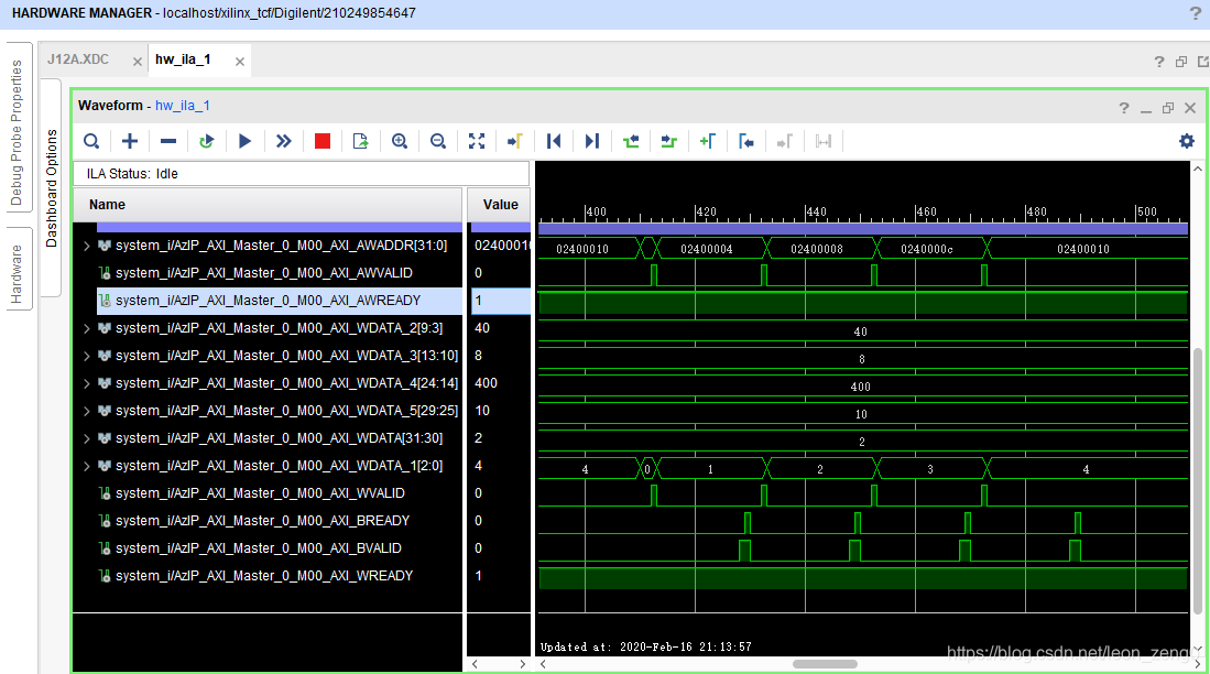
实测波形图
这2个实测波形图,通过Vivado 下的集成逻辑分析仪ILA在开发板上实际测试获得。其方法请见 Vivado的集成逻辑分析仪ILA 在有sdk 下的应用入门。
axi4 读流程: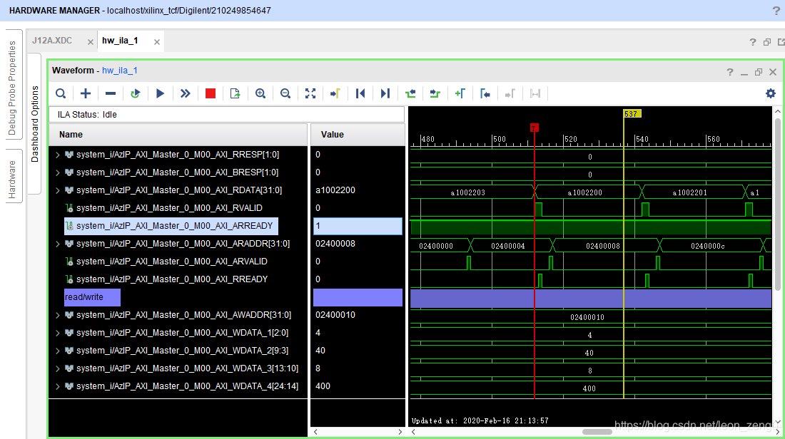
axi4 写流程:
这个地址线分成了好几组,只有WDATA[2:0]是变化的,也不知道怎么控制能分成几组。
AzIP_AXI_Master_v1_0.v 代码分析
这个文件比较小,3kb大小,只是一个接口封装,列出所有接口,然后调用实例
// Instantiation of Axi Bus Interface M00_AXI
这行开始就是调用实例。
AzIP_AXI_Master_v1_0_M00_AXI.v 文件 代码分析
这个是我们分析的重点,代码实现都是在这里。
到 95,96行
output wire M_AXI_RREADY
);
一直是函数的说明,io等。
然后到110行,是2个辅助函数,
	// function called clogb2 that returns an integer which has the
	// value of the ceiling of the log base 2

	 function integer clogb2 (input integer bit_depth);
		 begin
		 for(clogb2=0; bit_depth>0; clogb2=clogb2+1)
			 bit_depth =
最低0.47元/天 解锁文章


 990
990

 被折叠的 条评论
为什么被折叠?
被折叠的 条评论
为什么被折叠?
 到【灌水乐园】发言


