


Electronic gadgets are an integral part of our day-to-day life. Lifeline of these gadgets/products are semiconductor IC/SoC/ASIC/FPGA which are mounted on the PCB (Printed Circuit Boards) & connected with each other to make the gadget operational. As per Moore’s law no. of transistors in an Integrated Circuit (IC) doubles every 18 months which turns out to be more functional features supported in the design and hence designs are getting more & more complex. The core challenge is to successfully verify this exponential growth happening towards the design side. To handle this design growth, there is substantial improvement in the VLSI functional verification technologies, approaches & methodologies in last couple of years.
This blog provides an overview of the Advanced Functional Verification Challenges, different technologies available today, different approaches which can be used & latest Constrained Random Verification (CRV) methodology with brief information on UVM (Universal Verification Methodology) as well.
1. Introduction
Since Hardware designs are getting more and more complex, the traditional approach to verify the designs using manually written tests i.e. Directed Test approach is difficult do and maintain for bigger & complex designs. There are corner cases which are either not humanly possible to imagine, code test for them or missed during the verification. Visual inspection of the waveforms in order to trace a design bug is always a tedious task. The amount of time we spent in verification now a days exceeded the time we spent in design, comprising of almost 70% of the total development effort.
The ultimate goals is – “Find Bugs Early & Fast”
We’ll discuss following topics in this paper:
- Functional Verification Requirements
- Functional Verification Technologies
- Functional Verification Approaches
- Functional Verification Methodologies
These topics will provide a good insight into these technical areas & will help to comprehend verification world!
2. Functional Verification Requirements
There are certain requirements which should be targeted in order to develop an effective and robust verification environment to verify the Design Under Test (DUT).
- Verify all the features/usecases & find all the bugs
- Re-usability
- Progress Measurement
- Automation
- Easy to write and maintain
Automation is the key to enhance the effectiveness for executing testcases, observing & analyzing results which could range from self-checking mechanism to functional coverage back annotation. Verification metrics helps to track & measure the progress of the verification completion. It helps to focus on the important functional scenarios prior to the corner cases being covered. Adopting various different techniques, like executable verification plan, we can assign priority & weightage to a particular feature to be tested. We can map feature to be tested to the specification document. Even the coverage results could be automatically back-annotated to the verification plan displaying the progress being made.
Re-usability needs to be another highly focused concept which is having an immense importance as far as functional verification is concerned. The more we develop verification components e.g. Agents, Stimulus, Scoreboard etc. which are re-usable vertically as well as horizontally across the projects, better is our ability to develop a robost verification environment in lesser time. Re-usability encouraged the verification community to come up with the concepts like “factory” and “configuration” in the latest verification methodology which helped various verification engineers in multiple roles like developers, integrators & test developers to work in tandem & create different interesting stimulus scenarios to test the DUT.
Modularity is another concept which is important to consider while developing verification components & environment. Its helps to better manage the work product which could be OOPs based classes – child classes extended from the parent classes etc. Inheritance & Polymorphism supported by SystemVerilog facilitate these kind of modular features. Coding guidelines is another important parameter for an effective verification environment. Amoung the numerious other benefits, it helps to maintain the code in a consistent way & also helps in debugging with ease.
3. Functional Verification Technologies
In industry, there are two technologies which are used to perform Functional Verification. In Simulation Based Verification, Design Inputs are stimulated by the dynamic vectors injected by the verification engineer & output is measured against the expected values which can be termed as golden values.
- Simulation Based Verification
- Formal Verification
- Equivalence Checking
- Formal Property (Assertion) Checking

Figure 1: Simulation Process (Source: Mentor Graphics)
Another approach is Formal Verificaiton, where verification engineer starts out by stating what output behavior is desirable and then let the formal verification tool to prove or disprove it. Verification engineer do not concern with the input stimuli at all. Usually this approach is called Formal Property Checking. In Equivalence Checking, 2 different design stage outputs are compared to be functionally equivalent which is totally EDA tool driven. Example of these design stage outputs could be RTL design vs Gate level netlist after synthesis or pre-scan inserted netlist vs. post-scan inserted netlist.
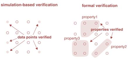
Figure 2: Simulation Vs Formal Verificaiton
Simulating a vector can be conceptually viewed as verifying a point in the input space. With this view, simulation-based verification can be seen as verification through input space sampling. Unless all points are sampled, there exists a possibility that an error escapes verification. As opposed to working at the point level, formal verification works at the property level. Given a property, formal verification exhaustively searches all possible input and state conditions for failures. If viewed from the perspective of output, simulation-based verification checks one output point at a time; formal verification checks a group of output points at a time (a group of output points make up a property).
4. Functional Verification Approaches
In a complex SoC design flow functional verification is very important; any behavioral or functional bug escaping this phase will not be detected in the subsequent implementation phases and will surface only after the first silicon is integrated into the target system, resulting in costly design and silicon iterations. To handle this challenge, a number of academic and industrial research laboratories have been carrying out research on different approaches for functional verification. Five such dynamic vectors based approaches are listed below – neither of one approach out of these is sufficient & fully capable to ensure bug-free verification. These approaches works in tandem & together makes a best possible solution.
- Directed Verification
- Constrained Random Verification
- Coverage Driven Verification
- Assertion Based Verification
- Emulation Based Verification
Directed verification is the traditional approach to functionally verify the Designs using manually created testcases based on the features to be tested. Directed tests approach may work well for smaller designs, but for ever growing size and functionalities of the SoC/IP where it may require thousands of testcases, this approach is encountering many missed functional issues and time-to-market challenge in fully verifying the Design.
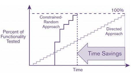
Figure 3: Directed Vs Constrained Random Approach
To overcome this limitation and improve verification productivity, the only way is reducing the time it takes to create working tests. Using constrained-random stimulus generation, scenarios can be generated in an automated fashion under the control of a set of rules, or constraints, specified by the user. SystemVerilog provides a vast array of language capabilities for describing complex verification environments, including constrained-random stimulus generation, object-oriented programming, multi-threaded capabilities, inter-process communication and synchronization, and functional coverage. These features allow users to develop testbenches that automate the generation of various scenarios for verification.
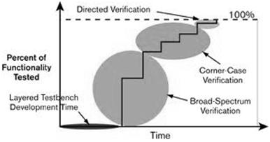
Figure 4: Verification Cycle using Constrained Random Approach
Figure 3 shows verification cycle using Constrained Random Verification approach i.e. Layered Testbench Development, testing larger design space (Orange color), testing very specific scenarios (Corner cases) & finally hitting the remaining holes using writing directed testcases.
Coverage driven verification serve critical purposes throughout the verification process. The one very important is to identify holes in the process by pointing to areas of the design that have not yet been sufficiently verified. This helps to direct the verification effort by answering the key question of what to do next — for example, which new directed test to write or how to vary/control the parameters for constrained-random testing.
Another even more important purpose is to – acts as an indicator of when verification is thorough enough to tape out. Coverage provides more than a simple yes/no answer, incremental improvement in coverage metrics helps to assess verification progress and thoroughness, leading to the point at which the development team has the confidence to tape out the design. In fact, coverage is so critical that most advanced, automated approaches implement coverage-driven verification, in which coverage metrics guide each step of the process.
Coverage is divided into two main categories: code coverage and functional coverage (Fig 6). Code coverage, in its many forms (line coverage, toggle coverage, expression coverage), is typically an automated process that tells whether all of the code in a particular RTL design description was exercised during a particular simulation run (or set of runs). Functional coverage drived from Functional coverage model helps to indicate the covered/uncovered functional points in the design. It could be further classified into Point coveage, Transistion coverage and Cross coverage.
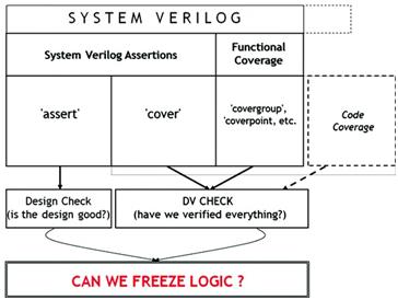
Figure 5: Coverage and Assertion Application
Assertions can enhance the capabilities and productivity of any verification environment. Assertions are in simple terms – the statements of the design intent. Beyond that, Assertions can be helpful in many different phase of the verification cycles e.g. Protocol Checkers, Assertion coverage and the same set of assertions can be used during emulation.
During the verification process, engineers typically use a variety of tools. They use logic simulators for block-level verification, which traditionally simulate at 10–1000 clock cycles per second. However, the performance of logic simulators goes down drastically with increased design size, rendering them practically impossible to use for system-level integration testing. Simulation speed is also limited by the number of clock cycles required to run a design; for example, a full video frame in even a moderately sized design will take many, many clock cycles and thus a long time to run in pure simulation.
Emulators aim to fill this gap. By mimicking the actual hardware in an emulator it can be run at a few million clock cycles per second. In this approach, RTL design in the emulator interacts with the Testbench running on a workstation, as shown in Figure 6.
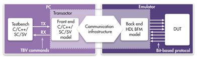
Figure 6: Emulation Based Verification (Source: Synopsys)
5. Functional Verification Methodologies
Any methodology guides us towards “how to do” things. Similarly Advanced Functional Verification Methodology helps the verification community to provide a framework which if used properly & as suggested results in reusable verification components (UVC/OVC/VIP), better controllability via Configuration support, Layered Testbench framework & performance improvement.
5.1 Universal Verification Methodology (UVM)
In December 2009, a technical subcommittee of Accellera — a standards organization in the electronic design automation (EDA) industry — voted to establish the UVM (Universal Verification Methodology) and decided to base this new standard on the Open Verification Methodology (OVM-2.1.1), a verification methodology developed jointly in 2007 by Cadence Design Systems and Mentor Graphics.
On February 21, 2011, Accellera approved the 1.0 version of UVM. UVM 1.0 includes a Reference Guide, a Reference Implementation in the form of a SystemVerilog base class library, and a User Guide. UVM was not built from scratch. It is the culmination of many independent efforts in the verification methodology space. Its heritage includes AVM, URM, VMM, and OVM.
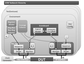
Figure 7: UVM Testbench Hierarchy
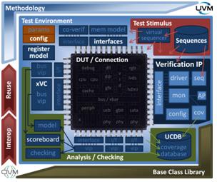
Figure 8: UVM/OVM Framework (Source: Mentor Graphics)
6. Summary
In this blog, we dicussed different verification technologies, approaches & methodologies. As SoC size is growing at a rapid pace, we discussed why & how the functional verification community moved from directed approach to constrained random approach & next moving towards emulation. To tackle productivity, performance & bug free designs, UVM & SystemVerilog has become immensely popular and being adopted by large numbers of semiconductor organizations in last couple of years. Another good part UVM and SystemVerilog emerged as the unanimously accepted among EDA and verification users community.


 229
229


 被折叠的 条评论
为什么被折叠?
被折叠的 条评论
为什么被折叠?
 到【灌水乐园】发言


