


 本文深入解析了TI DSP2833x系列微控制器中看门狗模块的工作原理与配置方法。详细介绍了通过修改系统控制和状态寄存器SCSR以及看门狗控制寄存器WDCR来实现看门狗的启动、停止和中断控制。并通过实例代码展示了如何在主程序中使用看门狗,并解释了关键寄存器的作用。
主程序
先看一下TI提供的看门狗例程源程序,如下
// TI File $Revision: /main/8 $
// Checkin $Date: August 10, 2007   09:07:57 $
//###########################################################################
//
// FILE:   Example_2833xWatchdog.c
//
// TITLE:  DSP2833x Watchdog interrupt test program.
//
// ASSUMPTIONS:
//
//    This program requires the DSP2833x header files.
//
//    As supplied, this project is configured for "boot to SARAM"
//    operation.  The 2833x Boot Mode table is shown below.
//    For information on configuring the boot mode of an eZdsp,
//    please refer to the documentation included with the eZdsp,
//
//       $Boot_Table:
//
//         GPIO87   GPIO86     GPIO85   GPIO84
//          XA15     XA14       XA13     XA12
//           PU       PU         PU       PU
//        ==========================================
//            1        1          1        1    Jump to Flash
//            1        1          1        0    SCI-A boot
//            1        1          0        1    SPI-A boot
//            1        1          0        0    I2C-A boot
//            1        0          1        1    eCAN-A boot
//            1        0          1        0    McBSP-A boot
//            1        0          0        1    Jump to XINTF x16
//            1        0          0        0    Jump to XINTF x32
//            0        1          1        1    Jump to OTP
//            0        1          1        0    Parallel GPIO I/O boot
//            0        1          0        1    Parallel XINTF boot
//            0        1          0        0    Jump to SARAM	    <- "boot to SARAM"
//            0        0          1        1    Branch to check boot mode
//            0        0          1        0    Boot to flash, bypass ADC cal
//            0        0          0        1    Boot to SARAM, bypass ADC cal
//            0        0          0        0    Boot to SCI-A, bypass ADC cal
//                                              Boot_Table_End$
//
// DESCRIPTION:
//
//   This program exercises the watchdog.
//
//   First the watchdog is connected to the WAKEINT interrupt of the
//   PIE block.  The code is then put into an infinite loop.
//
//   The user can select to feed the watchdog key register or not
//   by commenting one line of code in the infinite loop.
//
//   If the watchdog key register is fed by the ServiceDog function
//   then the WAKEINT interrupt is not taken.  If the key register
//   is not fed by the ServiceDog function then WAKEINT will be taken.
//
//      Watch Variables:
//         LoopCount for the number of times through the infinite loop
//         WakeCount for the number of times through WAKEINT
//
//###########################################################################
// $TI Release: DSP2833x Header Files V1.01 $
// $Release Date: September 26, 2007 $
//###########################################################################


#include "DSP2833x_Device.h"     // Headerfile Include File
#include "DSP2833x_Examples.h"   // Examples Include File

// Prototype statements for functions found within this file.
interrupt void wakeint_isr(void);

// Global variables for this example
Uint32 WakeCount;
Uint32 LoopCount;

void main(void)
{

// Step 1. Initialize System Control:
// PLL, WatchDog, enable Peripheral Clocks
// This example function is found in the DSP2833x_SysCtrl.c file.
   InitSysCtrl();

// Step 2. Initalize GPIO:
// This example function is found in the DSP2833x_Gpio.c file and
// illustrates how to set the GPIO to it's default state.
// InitGpio();  // Skipped for this example

// Step 3. Clear all interrupts and initialize PIE vector table:
// Disable CPU interrupts
   DINT;

// Initialize PIE control registers to their default state.
// The default state is all PIE interrupts disabled and flags
// are cleared.
// This function is found in the DSP2833x_PieCtrl.c file.
   InitPieCtrl();

// Disable CPU interrupts and clear all CPU interrupt flags:
   IER = 0x0000;
   IFR = 0x0000;

// Initialize the PIE vector table with pointers to the shell Interrupt
// Service Routines (ISR).
// This will populate the entire table, even if the interrupt
// is not used in this example.  This is useful for debug purposes.
// The shell ISR routines are found in DSP2833x_DefaultIsr.c.
// This function is found in DSP2833x_PieVect.c.
   InitPieVectTable();

// Interrupts that are used in this example are re-mapped to
// ISR functions found within this file.
   EALLOW;	// This is needed to write to EALLOW protected registers
   PieVectTable.WAKEINT = &wakeint_isr;
   EDIS;   // This is needed to disable write to EALLOW protected registers

// Step 4. Initialize all the Device Peripherals:
// This function is found in DSP2833x_InitPeripherals.c
// InitPeripherals(); // Not required for this example

// Step 5. User specific code, enable interrupts:

// Clear the counters
   WakeCount = 0; // Count interrupts
   LoopCount = 0; // Count times through idle loop

// Connect the watchdog to the WAKEINT interrupt of the PIE
// Write to the whole SCSR register to avoid clearing WDOVERRIDE bit
   EALLOW;
   SysCtrlRegs.SCSR = BIT1;
   EDIS;

// Enable WAKEINT in the PIE: Group 1 interrupt 8
// Enable INT1 which is connected to WAKEINT:
   PieCtrlRegs.PIECTRL.bit.ENPIE = 1;   // Enable the PIE block
   PieCtrlRegs.PIEIER1.bit.INTx8 = 1;   // Enable PIE Gropu 1 INT8
   IER |= M_INT1;                       // Enable CPU int1
   EINT;                                // Enable Global Interrupts

// Reset the watchdog counter
   ServiceDog();

// Enable the watchdog
   EALLOW;
   SysCtrlRegs.WDCR = 0x0028;
   EDIS;

// Step 6. IDLE loop. Just sit and loop forever (optional):
   for(;;)
   {
      LoopCount++;

      // Uncomment ServiceDog to just loop here
      // Comment ServiceDog to take the WAKEINT instead
    // ServiceDog();
   }


}


// Step 7. Insert all local Interrupt Service Routines (ISRs) and functions here:
// If local ISRs are used, reassign vector addresses in vector table as
// shown in Step 5

interrupt void wakeint_isr(void)
{
	WakeCount++;

	// Acknowledge this interrupt to get more from group 1
	PieCtrlRegs.PIEACK.all = PIEACK_GROUP1;
}

//===========================================================================
// No more.
//===========================================================================
以上程序就是通过两个全局变量来计数看门狗触发的次数WakeCount以及最后死循环的循环次数LoopCount。通过CCS6.0调试功能可是实时看到两个变量的变化。
可以通过注释死循环里面ServiceDog()函数来决定是否喂狗。若每次循环都喂狗,就可以发现循环次数会不断增加,而中断服务程序就不会触发,即WakeCount为0;
否则的话,将喂狗函数注释掉,那么,中断服务程序就会不断被触发WakeCount也就不断增加,即看门狗不断触发。
下面,我们就研究一下,看门狗被打开与关闭的条件。
相关寄存器
先引用<手把手教你学DSP(第二版)>第88页的寄存器说明
看门狗控制寄存器WDCR
| 位 | 名称 | 描述 |
|---|---|---|
| 15~8 | 保留 | |
| 7 | WDFLAG | 看门狗复位状态标志位;0:不满足标志位,1:满足了复位条件 |
| 6 | WDDIS | 看门狗禁止;0:使能看门狗功能;1:禁止看门狗功能 |
| 5~3 | WDCHK | 看门狗逻辑校验位,必须写101 |
| 2~0 | WDPS | 看门狗时钟分频,若为000或001时候,看门狗时钟频率=晶振频率/512,其余时候,看门狗时钟频率=晶振频率/512/(2^(WDPS-1)) |
系统控制和状态寄存器SCSR
| 位 | 名称 | 描述 |
|---|---|---|
| 15~3 | 保留 | |
| 2 | WDINTS | 看门狗中断状态位,反应看门狗模块 W D I N T ‾ \overline{{\rm WDINT}} WDINT信号状态 |
| 1 | WDENINT | 0:将复位信号 W D R S T ‾ \overline{{\rm WDRST}} WDRST屏蔽,将中断信号 W D I N T ‾ \overline{{\rm WDINT}} WDINT使能;1:将复位信号 W D R S T ‾ \overline{{\rm WDRST}} WDRST使能,将中断信号 W D I N T ‾ \overline{{\rm WDINT}} WDINT屏蔽; |
| 0 | WDOVERRIDE | 如果该位是1,允许用户改变看门狗控制器寄存器屏蔽位WDDIS;如果通过将该位置1将其清零,用户不能改变WDDIS位置的设置。若该位被清除,只有系统复位后才能改变状态。用户可以随时读取该状态位。 |
注意
- 以上基本就是引用书上的原文,通过这两个寄存器的设置基本上就可以实现DSP看门狗打开与屏蔽功能。
- 书中关于WDOVERRIDE位的设置描述非常模糊。而该位直接影响看门狗的开启与关闭,所以,我个人的实验结果终结如下
- 该位可以读取与写入,且读取与写入的数据并不相同,也就是说,当该位写入1时,读取的结果为0,该位置0后读取的结果为1
- 读取到
- 0:不能通过将WDDIS置1的方式关闭看门狗功能。此时,看门狗功能一直开启,知道系统复位。
- 1:可以通过WDDIS开启或者关闭看门狗功能。
- 写入数据
- 0:可以通过WDDIS位开启或者关闭看门狗。
- 1:开启看门狗功能,直到系统重启。不可以通过WDDIS位关闭看门狗,也无法重新将WDOVERRIDE置0来重新关闭看门狗。
程序实现
	//配置SCSR
	EALLOW;//关闭保护、
	//将中断信号WDINT使能,且允许屏蔽看门狗
	SysCtrlRegs.SCSR = 0x0002;//0010
	EDIS;//打开保护

	//配置WDCR
	EALLOW;
	SysCtrlRegs.WDCR = 0x0028;//0010 1000:使能看门狗,分频数为512
	EDIS;

	EALLOW;
    SysCtrlRegs.WDCR= 0x0068;//0110 1000;关闭看门狗
    EDIS;
上述程序可以实现看门狗的关闭。
	//配置SCSR
	EALLOW;//关闭保护、
	//将中断信号WDINT使能,打开且不允许屏蔽看门狗
	SysCtrlRegs.SCSR = 0x0003;//0011
	EDIS;//打开保护

	//配置WDCR
	EALLOW;
	SysCtrlRegs.WDCR = 0x0028;//0010 1000:看门狗已经打开
	EDIS;

	EALLOW;
    SysCtrlRegs.WDCR= 0x0068;//0110 1000;不起作用。
    EDIS;
上述程序不能关闭看门狗。
更新
关于SCSR寄存器,我又参考了TI的官方手册。如下图:
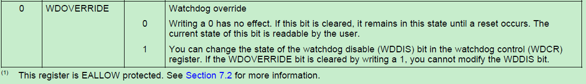
下方的中文介绍截取自<TMS320F28335DSP原理及开发编程>:


 1万+
1万+

 被折叠的 条评论
为什么被折叠?
被折叠的 条评论
为什么被折叠?
 到【灌水乐园】发言


