


In a diagram, a tick mark with a number next to it indicates the width of the vector (or "bus"), rather than drawing a separate line for each bit in the vector.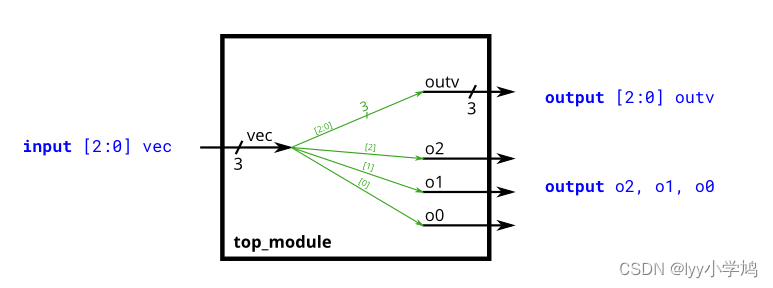
module top_module (
    input wire [2:0] vec,
    output wire [2:0] outv,
    output wire o2,
    output wire o1,
    output wire o0  ); // Module body starts after module declaration
assign outv=vec;
assign {o2,o1,o0}=vec;
endmodule
可以再次优化:一个assign 解决,一行代码即可,但是可读性变差。
A Bit of Practice
Build a combinational circuit that splits an input half-word (16 bits, [15:0] ) into lower [7:0] and upper [15:8] bytes.
`default_nettype none     // Disable implicit nets. Reduces some types of bugs.
module top_module(
    input wire [15:0] in,
    output wire [7:0] out_hi,
    output wire [7:0] out_lo );
assign 	out_hi=in[15:8];
assign	out_lo=in[7:0];
endmodule
A 32-bit vector can be viewed as containing 4 bytes (bits [31:24], [23:16], etc.). Build a circuit that will reverse the byte ordering of the 4-byte word.
AaaaaaaaBbbbbbbbCcccccccDddddddd => DdddddddCcccccccBbbbbbbbAaaaaaaa
This operation is often used when the endianness of a piece of data needs to be swapped, for example between little-endian x86 systems and the big-endian formats used in many Internet protocols.
module top_module(
    input [31:0] in,
    output [31:0] out );//

    assign out[31:24] = {in[7:0],in[15:8],in[23:16],in[31:24]};

endmodule
对原来的提示做了一个优化,一行代码解决问题
Build a circuit that has two 3-bit inputs that computes the bitwise-OR of the two vectors, the logical-OR of the two vectors, and the inverse (NOT) of both vectors. Place the inverse of in the upper half of (i.e., bits [5:3]), and the inverse of in the lower half. bout_nota
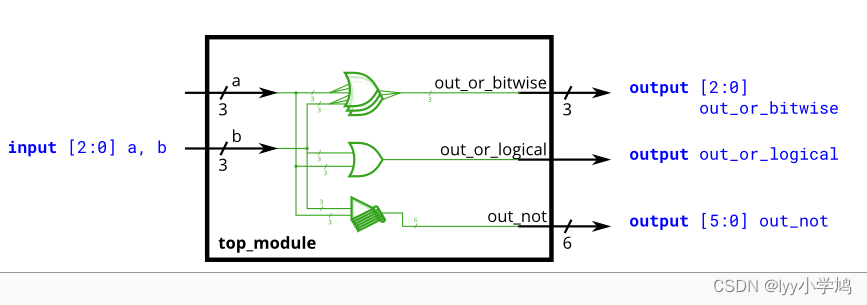
module top_module(
    input [2:0] a,
    input [2:0] b,
    output [2:0] out_or_bitwise,
    output out_or_logical,
    output [5:0] out_not
);
assign out_or_bitwise=a|b;
assign out_or_logical=a||b;
assign out_not={~b,~a};
// 按位与&  逻辑与&&  按位或|  逻辑或||
endmodule


 180
180


 被折叠的 条评论
为什么被折叠?
被折叠的 条评论
为什么被折叠?
 到【灌水乐园】发言


